EP0040219B1 - Data processor having common monitoring and memory loading and checking means - Google Patents
Data processor having common monitoring and memory loading and checking means Download PDFInfo
- Publication number
- EP0040219B1 EP0040219B1 EP80902214A EP80902214A EP0040219B1 EP 0040219 B1 EP0040219 B1 EP 0040219B1 EP 80902214 A EP80902214 A EP 80902214A EP 80902214 A EP80902214 A EP 80902214A EP 0040219 B1 EP0040219 B1 EP 0040219B1
- Authority
- EP
- European Patent Office
- Prior art keywords
- ram
- micro
- data processor
- monitoring
- variable mode
- Prior art date
- Legal status (The legal status is an assumption and is not a legal conclusion. Google has not performed a legal analysis and makes no representation as to the accuracy of the status listed.)
- Expired
Links
Images


Classifications
-
- G—PHYSICS
- G06—COMPUTING; CALCULATING OR COUNTING
- G06F—ELECTRIC DIGITAL DATA PROCESSING
- G06F11/00—Error detection; Error correction; Monitoring
- G06F11/22—Detection or location of defective computer hardware by testing during standby operation or during idle time, e.g. start-up testing
- G06F11/2205—Detection or location of defective computer hardware by testing during standby operation or during idle time, e.g. start-up testing using arrangements specific to the hardware being tested
- G06F11/2236—Detection or location of defective computer hardware by testing during standby operation or during idle time, e.g. start-up testing using arrangements specific to the hardware being tested to test CPU or processors
-
- G—PHYSICS
- G06—COMPUTING; CALCULATING OR COUNTING
- G06F—ELECTRIC DIGITAL DATA PROCESSING
- G06F11/00—Error detection; Error correction; Monitoring
- G06F11/07—Responding to the occurrence of a fault, e.g. fault tolerance
- G06F11/0703—Error or fault processing not based on redundancy, i.e. by taking additional measures to deal with the error or fault not making use of redundancy in operation, in hardware, or in data representation
- G06F11/0706—Error or fault processing not based on redundancy, i.e. by taking additional measures to deal with the error or fault not making use of redundancy in operation, in hardware, or in data representation the processing taking place on a specific hardware platform or in a specific software environment
- G06F11/0727—Error or fault processing not based on redundancy, i.e. by taking additional measures to deal with the error or fault not making use of redundancy in operation, in hardware, or in data representation the processing taking place on a specific hardware platform or in a specific software environment in a storage system, e.g. in a DASD or network based storage system
-
- G—PHYSICS
- G06—COMPUTING; CALCULATING OR COUNTING
- G06F—ELECTRIC DIGITAL DATA PROCESSING
- G06F11/00—Error detection; Error correction; Monitoring
- G06F11/07—Responding to the occurrence of a fault, e.g. fault tolerance
- G06F11/0703—Error or fault processing not based on redundancy, i.e. by taking additional measures to deal with the error or fault not making use of redundancy in operation, in hardware, or in data representation
- G06F11/0706—Error or fault processing not based on redundancy, i.e. by taking additional measures to deal with the error or fault not making use of redundancy in operation, in hardware, or in data representation the processing taking place on a specific hardware platform or in a specific software environment
- G06F11/073—Error or fault processing not based on redundancy, i.e. by taking additional measures to deal with the error or fault not making use of redundancy in operation, in hardware, or in data representation the processing taking place on a specific hardware platform or in a specific software environment in a memory management context, e.g. virtual memory or cache management
-
- G—PHYSICS
- G06—COMPUTING; CALCULATING OR COUNTING
- G06F—ELECTRIC DIGITAL DATA PROCESSING
- G06F11/00—Error detection; Error correction; Monitoring
- G06F11/30—Monitoring
- G06F11/3003—Monitoring arrangements specially adapted to the computing system or computing system component being monitored
- G06F11/3024—Monitoring arrangements specially adapted to the computing system or computing system component being monitored where the computing system component is a central processing unit [CPU]
-
- G—PHYSICS
- G06—COMPUTING; CALCULATING OR COUNTING
- G06F—ELECTRIC DIGITAL DATA PROCESSING
- G06F11/00—Error detection; Error correction; Monitoring
- G06F11/30—Monitoring
- G06F11/3003—Monitoring arrangements specially adapted to the computing system or computing system component being monitored
- G06F11/3037—Monitoring arrangements specially adapted to the computing system or computing system component being monitored where the computing system component is a memory, e.g. virtual memory, cache
-
- G—PHYSICS
- G06—COMPUTING; CALCULATING OR COUNTING
- G06F—ELECTRIC DIGITAL DATA PROCESSING
- G06F11/00—Error detection; Error correction; Monitoring
- G06F11/30—Monitoring
- G06F11/3089—Monitoring arrangements determined by the means or processing involved in sensing the monitored data, e.g. interfaces, connectors, sensors, probes, agents
-
- G—PHYSICS
- G11—INFORMATION STORAGE
- G11C—STATIC STORES
- G11C29/00—Checking stores for correct operation ; Subsequent repair; Testing stores during standby or offline operation
- G11C29/04—Detection or location of defective memory elements, e.g. cell constructio details, timing of test signals
- G11C29/08—Functional testing, e.g. testing during refresh, power-on self testing [POST] or distributed testing
- G11C29/12—Built-in arrangements for testing, e.g. built-in self testing [BIST] or interconnection details
- G11C29/18—Address generation devices; Devices for accessing memories, e.g. details of addressing circuits
- G11C29/30—Accessing single arrays
- G11C29/32—Serial access; Scan testing
-
- G—PHYSICS
- G06—COMPUTING; CALCULATING OR COUNTING
- G06F—ELECTRIC DIGITAL DATA PROCESSING
- G06F11/00—Error detection; Error correction; Monitoring
- G06F11/22—Detection or location of defective computer hardware by testing during standby operation or during idle time, e.g. start-up testing
- G06F11/2294—Detection or location of defective computer hardware by testing during standby operation or during idle time, e.g. start-up testing by remote test
Definitions
- the present invention relates to a data processor comprising storage devices for storing digital data; a logic circuitry interconnecting said storage devices for performing data processing operations; a monitoring unit for performing monitoring of digital data; a clock generator for generating clock signals: and means for generating monitor enable signals to cause the digital data to be propagated to the monitoring unit.
- a data processor comprising a storage device, logic circuitry, monitoring unit, clock generator and means for generating monitor enable signals in accordance with the above identified features is known from US-A-3,582,902.
- each storage device is connected to an auxiliary register such that the content of each storage device is copied into the auxiliary register when required. Thereafter the contents of the auxiliary register is propagated to the display unit when caused to do so by the provision of the monitor enable signals.
- auxiliary registers for an intermediate data storage of the contents of each storage device, however, increases the costs of the data processor and in addition thereto is space consuming.
- US ⁇ A ⁇ 4,183,461 (corresponding to JP-A-53112631 which is published on 2.10.78) concerns a fault-diagnosing apparatus and a method for an electronic computer having a central processing unit including a plurality of packages, carrying out fault-diagnosing in any of these circuits by using special fault-diagnosing circuits provided in the respective packages and using a common exclusively fault-diagnosing bus to which the fault-diagnosing circuits are jointly connected and through which a fault-diagnosing unit diagnoses faults in receiving signals denoting the interior status of the respective sequential circuit.
- Using exclusively fault-diagnosing circuits provided in every package and using more or less bulky selectors, to which combinational and flip- flop circuits are connected, is, however, involving great expenses by large electronic members.
- US ⁇ A ⁇ 3,964,088 discloses a multi-unit data processing system including an equipment for the execution of maintenance operations.
- shift registers each made of a hardware series connection of multi-bit and single-bit register members are provided in each unit of the multi-unit system.
- a plurality of additional auxiliary registers is necessary for monitoring the contents of the respective storage devices.
- a test means for testing large-scale integrated devices wherein the large scale integrated device comprises a linked pair of polarity-hold shift register latches.
- the first latch is desined to serve both system design and testing requirements whereas the second latch of this pair exists solely to enhance chip testability.
- the second latch has a single data input permanently connected to one output of its paired first latch, plus a single clock input for loading it from the first latch.
- the first latch can be set from two sources by two different clock inputs and has two outputs, reflecting its dual role as part of the test system and as a storage element for the system.
- variable mode registers capable of operating in either a normal mode, in which the register serves to provide digital storage of said data processor, or a monitoring mode, in which data is propagated through the register without first being transferred to separate register; said variable mode registers being interconnected by gating means so that during the monitoring mode they form a plurality of separately selectable strings; said monitor enable signals and said clock signals being applied to said gating means and to said variable mode registers of the selected string so as to cause the content thereof to be propagated directly to and from said monitoring unit via the other variable mode registers in the selected string; said data processor further comprises a plurality of selectively addressable RAMs containing micro-code for use in controlling data processing operations, addressing means for said RAMs, a RAM input-/ output register for each RAM comprised of a plurality of variable mode registers and micro- code loading means; each RAM being operative in response to a read signal to read out micro- code
- a conventional form of data processor 10 is illustrated typically including a plurality of storage devices S 1 ⁇ S n cooperating with logic circuitry 12 in providing data processing operations.
- Other conventional portions of a data processor are not shown in Fig. 1 for the sake of simplicity, but such portions may be considered to operate in cooperation with the storage devices S i -S n and logic circuitry 12 in a conventional manner.
- it is of particular advantage to employ variable mode, multi-bit shift register storage devices such as illustrated by the variable mode, 4-bit shift register 15 illustrated in Fig. 2.
- Such a shift register 15 may be implemented, for example, using a commercially available Texas Instruments 74S194 for an integrated circuit chip.
- the 4-bit variable mode shift register 15 includes: inputs 1 1 , 1 2 , 1 3 and 1 4 ; respective outputs 0 1 , O2, 0 3 and 0 4 ; a "Shift-Up" input for receiving input signals to be shifted through the register; a clear input for use in clearing the shift register to all "0" values; a clock input for receiving a clock signal whose leading edge, for example, is used to initiate shift register operations; and mode control inputs K 1 and K 2 to which mode control signals are applied for determining the particular mode in which the shift register is to operate.
- the mode control signals applied to inputs K 1 and K 2 may have the following meanings:
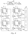
- Fig. 3 illustrates a preferred manner in accordance with the invention for interconnecting variable mode shift register storage devices, such as illustrated in Fig. 2, into a "String" for cooperation with a monitoring unit 20.
- Fig. 3 illustrates only a single String comprised of four 4-bit variable mode shift register devices 15a-15d, it will be understood that many such Strings are ordinarily provided in a data processor, and that more or less shift register storage devices may be provided in each String.
- variable mode storage devices 15a-15d are interconnected by gating circuitry G 1 so as to form a String when the gating circuitry G 1 is enabled by a monitor enable signal M s provided by a monitoring unit 20.
- the monitor clock Cm is applied to the clock input of each of shift register devices 15a-15d via gate circuitry G 2 which in response to monitoring control signal M s disconnects the normally provided processor clock while permitting the monitoring clock C m to be applied therethrough to the clock inputs of the shift register storage devices of the String. Since the four shift register devices 15a-15d in Fig. 3 form a 16-bit String, it will be understood that a total of 16 monitoring clocks C m are required to feed the sixteen states of the four shift register devices 15a-15d to the monitoring unit 20 for monitoring diagnostic and/or corrective purposes and then back again so that the shift register devices are returned to their original states or to corrected states, after which normal operations may be resumed. It will be evident from Fig.
- the String comprises the 16 bits constituted by the shift register outputs O 1a , O 2a , 0 3 a, 0 4 ar O 1b , 0 2b i O 3b , 0 4b, O 1c , O 2c , O 3c , O 4c , O 1d , O 2d, O 3d , 0 4d, wherein the a, b, c and d subscripts identify the respective one of shift registers 15a, 15b, 15c and 15d to which the outputs 0 1 , O2, 0 3 , 0 4 correspond.
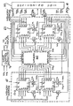
- FIG. 4 illustrates one type of monitoring unit 20 which may be employed.
- the operation of the monitoring unit 20 is initiated by a Monitor Instruction applied to a decoder 30 which derives therefrom a String address S " and a comparison data address CD A which are supplied to address registers 32 and 34, respectively.
- the String address S A applied to address register 32 in Fig. 4 selects from a String selector memory 35 a particular one of monitor enable signals M s1 ⁇ M sn for enabling the gating circuitry G 1 and G 2 of a selected String for feeding the shift register states of the shift register storage devices making up the selected String to the monitoring unit 20 and back again as described previously in connection with Fig. 3.
- the Decoder 30 also applies a count signal J to a monitor clock generator 36 for producing a predetermined number of monitor clocks which is determined by the number of bits in the selected String.
- the comparison data address C DA applied to address register 34 selects from a comparison data memory 38 a particular comparison data word CD having values corresponding to the states of the shift register storage devices of the select String, the selected comparison data word being applied to a shift register storage device 42 which may be of conventional form. Since the four 4-bit shift register storage devices provide a total of sixteen bits to be monitored, the corresponding comparison data word will likewise have sixteen bits and the shift register storage device 42 will accordingly be adapted to store at least sixteen bits.
- the bits of the selected String (provided as illustrated in Fig. 3) are serially loaded into a shift register storage device 44 which may also be of conventional form, and likewise is adapted to accommodate the sixteen bits fed thereto by the shift register storage devices of the selected String under the control of the monitor clock C m .
- the timing of the loading of the shift register devices 42 and 44 is chosen so that the sixteen bits of the selected String and the corresponding comparison data word are simultaneously stored in shift register storage devices 42 and 44, respectively, at which time they are then compared by a comparator 48 and the results of the comparison indicated by a display 50 or other appropriate device. Meanwhile, the sixteen bits from the selected String continue to be shifted under the control of monitor clock Cm and after a total of 16 clocks are returned via gating circuitry 55 back to their respective shift register devices 15a-15d in Fig. 3.
- the comparator 48 In the event the comparator 48 detects an error between one or more bits of the selected String and the corresponding comparison data word, the comparator 48 provides an appropriate signal to gating circuitry 55 which causes the bits of the comparison data word (or any desired number of bits thereof) in shift register storage device 42 to be shifted to the shift register storage devices of the selected String instead of those in shift register storage device 44.
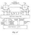
- a data processor may be implemented as a plurality of separately operating modules M 1 -M N , each including a RAM whose stored micro-code controls module operation.
- modules M 1 -M N each including a RAM whose stored micro-code controls module operation.
- the various interconnections provided between the modules and between each module and its respective RAM for non-monitoring data processing purposes are not shown since they are not pertinent to the present invention.
- each of modules M L -M N is provided with a micro-code storing RAM and its own set of one or more Strings of shift register storage devices of the type illustrated in Figs. 2 and 3. Each such String is indicated in Fig.
- Fig. 5 It is additionally of advantage to provide one or more of the modules in Fig. 5 with at least one monitoring String, these being indicated in Fig. 5 by the capital letter "T" having a subscript denoting the corresponding module.
- These monitoring Strings are provided in a manner so that the shift register storage devices of which each is comprised are not themselves involved in data processing operations, but rather are used for monitoring purposes within their respective modules. Accordingly, this permits each module to be individually monitored via a respective monitoring String while normal data processing operations are occurring.
- FIG. 6 illustrates, for example, a memory 60 having an input-output register 63 comprised of two variable mode shift register storage devices 15-1 and 15-2, each of which is preferably of the type illustrated in Fig. 2.
- a memory address register 65 is also provided using two such variable mode shift register storage devices 15-3 and 15-4 which it will be seen are connected with devices 15-1 and 15-2 to form a String in the same manner as illustrated in Fig. 3.
- the RAM of each of the modules illustrated in Fig. 5 is preferably arranged in the manner illustrated in Fig. 6.
- the monitoring unit 20 then provides a RAM address which is loaded in parallel into the RAM address register 65. This RAM address corresponds to the selected RAM states which it is desired be accessed.
- the monitoring unit 20 provides a memory write signal M w which causes the corrected memory states returned to the memory input-output register 63 to be written into the memory 60 at the originally addressed location initially loaded into address register 65.
- control signals M n , M, and M w and the memory address provided by the monitoring unit for use in the illustrative embodiment of Fig. 6 may be obtained from the decoder 30 in Fig. 4 as a result of decoding a monitoring instruction which is specifically provided to include such signals in order to provide for the memory monitoring operation described. It will also be understood with reference to Fig. 4 that, in response to such a monitor instruction, the decoder 30 causes the monitor clock generator 36 to provide appropriate clock signals for use in loading the memory address register 65 and the input-output register 63 in Fig. 6 as well as providing clock pulses for shifting purposes as previously described.
- a loading operation of a selected location in the RAM operation is the same as described above in the case of a correction, except that the new states written into the RAM at the selected location constitute the new micro- code which it is desired be loaded at that RAM location.
- a loading instruction is provided to decoder 30 which causes address register 34 to read out from memory 38 into shift register 42 the desired new micro-code data which is to be loaded, rather than comparison data as in a monitoring or checking operation.
- the comparator 48 conveniently serves to cause return (via gating circuitry 55 and the selected String) of the new micro-code data (when different from the existing micro-code) to the RAM input-output register for writing into the selected RAM location.
Abstract
Description
- The present invention relates to a data processor comprising storage devices for storing digital data; a logic circuitry interconnecting said storage devices for performing data processing operations; a monitoring unit for performing monitoring of digital data; a clock generator for generating clock signals: and means for generating monitor enable signals to cause the digital data to be propagated to the monitoring unit.
- A data processor comprising a storage device, logic circuitry, monitoring unit, clock generator and means for generating monitor enable signals in accordance with the above identified features is known from US-A-3,582,902.
- The monitoring of each of the storage devices of the known data processor is accomplished in that each storage device is connected to an auxiliary register such that the content of each storage device is copied into the auxiliary register when required. Thereafter the contents of the auxiliary register is propagated to the display unit when caused to do so by the provision of the monitor enable signals. The necessity of auxiliary registers for an intermediate data storage of the contents of each storage device, however, increases the costs of the data processor and in addition thereto is space consuming.
- US―A―4,183,461 (corresponding to JP-A-53112631 which is published on 2.10.78) concerns a fault-diagnosing apparatus and a method for an electronic computer having a central processing unit including a plurality of packages, carrying out fault-diagnosing in any of these circuits by using special fault-diagnosing circuits provided in the respective packages and using a common exclusively fault-diagnosing bus to which the fault-diagnosing circuits are jointly connected and through which a fault-diagnosing unit diagnoses faults in receiving signals denoting the interior status of the respective sequential circuit. Using exclusively fault-diagnosing circuits provided in every package and using more or less bulky selectors, to which combinational and flip- flop circuits are connected, is, however, involving great expenses by large electronic members.
- US―A―3,964,088 discloses a multi-unit data processing system including an equipment for the execution of maintenance operations. For checking, monitoring, and maintenance purposes shift registers each made of a hardware series connection of multi-bit and single-bit register members are provided in each unit of the multi-unit system. Thus, a plurality of additional auxiliary registers is necessary for monitoring the contents of the respective storage devices.
- From the article "Level-Sensitive Scan Design tests chips, boards, system", pages 108 to 110 published by ELECTRONICS, vol. 52, no. 6, March 15, 1979, a test means for testing large-scale integrated devices is known wherein the large scale integrated device comprises a linked pair of polarity-hold shift register latches. The first latch is desined to serve both system design and testing requirements whereas the second latch of this pair exists solely to enhance chip testability. The second latch has a single data input permanently connected to one output of its paired first latch, plus a single clock input for loading it from the first latch. The first latch can be set from two sources by two different clock inputs and has two outputs, reflecting its dual role as part of the test system and as a storage element for the system. Its test input is connected to the output of the second latch output of a different shift register latch, and its clock input loads it with data from said source. Thus, for monitoring the storage device in form of the first shift register latch an additional or auxilliary register in the form of the second latch is necessary which enhances the costs of the whole large scale integrated device or data processor and in addition is space consuming.
- It is an object of the present invention to make the internal states of one or more micro-code storing devices readily accessible for loading, changing, correcting or checking purposes without the need of auxiliary registers, additional selectors or special diagnosing circuits.
- This object of the invention is solved by a data processor which is characterized in that those of said storage devices having a content to be monitored are variable mode registers capable of operating in either a normal mode, in which the register serves to provide digital storage of said data processor, or a monitoring mode, in which data is propagated through the register without first being transferred to separate register; said variable mode registers being interconnected by gating means so that during the monitoring mode they form a plurality of separately selectable strings; said monitor enable signals and said clock signals being applied to said gating means and to said variable mode registers of the selected string so as to cause the content thereof to be propagated directly to and from said monitoring unit via the other variable mode registers in the selected string; said data processor further comprises a plurality of selectively addressable RAMs containing micro-code for use in controlling data processing operations, addressing means for said RAMs, a RAM input-/ output register for each RAM comprised of a plurality of variable mode registers and micro- code loading means; each RAM being operative in response to a read signal to read out micro- code from a RAM location selected by said addressing means into its respective RAM input-/ output register; each RAM also being operative in response to a write signal to write micro-code contained in its respective RAM input-/output register into a RAM location selected by said addressing means; and said monitoring unit and said micro-code loading means including means selectively providing an address for said addressing means and said read signal or said write signal for a selected RAM.
- The specific nature of the invention as well as other objects, features, advantages and uses thereof will become readily apparent from the following detailed description taken in conjunction with the accompanying drawings.
-
- Fig. 1 is a generalized block diagram illustrating how storage devices are typically interconnected by logic circuitry in a conventional data processor.
- Fig. 2 is a block representation of a variable mode shift register storage device which is preferably employed for providing digital storage in a data processing system incorporating the invention.
- Fig. 3 is a block diagram illustrating how the variable mode shift register storage devices of Fig. 2 may be interconnected in accordance with the invention to form a String for cooperation with a monitoring unit.
- Fig. 4 is a block diagram illustrating an example of a monitoring unit which may be employed in accordance with the invention.
- Fig. 5 is a block diagram illustrating how the present invention may advantageously be employed with a modular orgnized data processor.
- Fig. 6 is a block diagram illustrating how selectable storage states within a memory are made accessible for monitoring and/or micro-code loading or changing.
- Like characters and numerals refer to like elements and components throughout the figures of the drawings.
- Referring initially to Fig. 1, a conventional form of data processor 10 is illustrated typically including a plurality of storage devices S1―Sn cooperating with
logic circuitry 12 in providing data processing operations. Other conventional portions of a data processor are not shown in Fig. 1 for the sake of simplicity, but such portions may be considered to operate in cooperation with the storage devices Si-Sn andlogic circuitry 12 in a conventional manner. In the preferred embodiments of the present invention disclosed herein, it is of particular advantage to employ variable mode, multi-bit shift register storage devices such as illustrated by the variable mode, 4-bit shift register 15 illustrated in Fig. 2. Such a shift register 15 may be implemented, for example, using a commercially available Texas Instruments 74S194 for an integrated circuit chip. - As shown in Fig. 2, the 4-bit variable mode shift register 15 includes: inputs 11, 12, 13 and 14; respective outputs 01, O2, 03 and 04; a "Shift-Up" input for receiving input signals to be shifted through the register; a clear input for use in clearing the shift register to all "0" values; a clock input for receiving a clock signal whose leading edge, for example, is used to initiate shift register operations; and mode control inputs K1 and K2 to which mode control signals are applied for determining the particular mode in which the shift register is to operate. Typically, the mode control signals applied to inputs K1 and K2 may have the following meanings:
- K1K2=00=No Change;
- K1K2=11=Parallel Load; and
- K1K2=01=Shift Up.
- It will be understood that when:
- K1K2=11=Parallel Load,
- Fig. 3 illustrates a preferred manner in accordance with the invention for interconnecting variable mode shift register storage devices, such as illustrated in Fig. 2, into a "String" for cooperation with a
monitoring unit 20. Although Fig. 3 illustrates only a single String comprised of four 4-bit variable modeshift register devices 15a-15d, it will be understood that many such Strings are ordinarily provided in a data processor, and that more or less shift register storage devices may be provided in each String. - Now considering Fig. 3 in more detail, it will be understood that variable
mode storage devices 15a-15d are interconnected by gating circuitry G1 so as to form a String when the gating circuitry G1 is enabled by a monitor enable signal Ms provided by amonitoring unit 20. The monitor enable signal Ms is also used to causemode control circuitry 22 to provide Shift Up mode control signals (K1K2=01) to the mode control inputs KlK2 of shiftregister storage devices 15a-15d, thereby causing serial feeding of the respective sixteen states of the four 4-bit shiftregister storage devices 15a-15d to themonitoring unit 20 and then back again to their respective shiftregister storage devices 15a-15d under the control of a monitor clock Cm provided by themonitoring unit 20. The monitor clock Cm is applied to the clock input of each ofshift register devices 15a-15d via gate circuitry G2 which in response to monitoring control signal Ms disconnects the normally provided processor clock while permitting the monitoring clock Cm to be applied therethrough to the clock inputs of the shift register storage devices of the String. Since the fourshift register devices 15a-15d in Fig. 3 form a 16-bit String, it will be understood that a total of 16 monitoring clocks Cm are required to feed the sixteen states of the fourshift register devices 15a-15d to themonitoring unit 20 for monitoring diagnostic and/or corrective purposes and then back again so that the shift register devices are returned to their original states or to corrected states, after which normal operations may be resumed. It will be evident from Fig. 3 that the String comprises the 16 bits constituted by the shift register outputs O1a, O2a, 03a, 04ar O1b, 02bi O3b, 04b, O1c, O2c, O3c, O4c, O1d, O2d, O3d, 04d, wherein the a, b, c and d subscripts identify the respective one ofshift registers - Reference is now directed to Fig. 4 which illustrates one type of
monitoring unit 20 which may be employed. As indicated in Fig. 4, the operation of themonitoring unit 20 is initiated by a Monitor Instruction applied to adecoder 30 which derives therefrom a String address S" and a comparison data address CDA which are supplied toaddress registers - The String address SA applied to
address register 32 in Fig. 4 selects from a String selector memory 35 a particular one of monitor enable signals Ms1―Msn for enabling the gating circuitry G1 and G2 of a selected String for feeding the shift register states of the shift register storage devices making up the selected String to themonitoring unit 20 and back again as described previously in connection with Fig. 3. - The
Decoder 30 also applies a count signal J to amonitor clock generator 36 for producing a predetermined number of monitor clocks which is determined by the number of bits in the selected String. - Still with reference to Fig. 4, the comparison data address CDA applied to
address register 34 selects from a comparison data memory 38 a particular comparison data word CD having values corresponding to the states of the shift register storage devices of the select String, the selected comparison data word being applied to a shiftregister storage device 42 which may be of conventional form. Since the four 4-bit shift register storage devices provide a total of sixteen bits to be monitored, the corresponding comparison data word will likewise have sixteen bits and the shiftregister storage device 42 will accordingly be adapted to store at least sixteen bits. The bits of the selected String (provided as illustrated in Fig. 3) are serially loaded into a shiftregister storage device 44 which may also be of conventional form, and likewise is adapted to accommodate the sixteen bits fed thereto by the shift register storage devices of the selected String under the control of the monitor clock Cm. - The timing of the loading of the
shift register devices register storage devices comparator 48 and the results of the comparison indicated by adisplay 50 or other appropriate device. Meanwhile, the sixteen bits from the selected String continue to be shifted under the control of monitor clock Cm and after a total of 16 clocks are returned viagating circuitry 55 back to their respectiveshift register devices 15a-15d in Fig. 3. In the event thecomparator 48 detects an error between one or more bits of the selected String and the corresponding comparison data word, thecomparator 48 provides an appropriate signal to gatingcircuitry 55 which causes the bits of the comparison data word (or any desired number of bits thereof) in shiftregister storage device 42 to be shifted to the shift register storage devices of the selected String instead of those in shiftregister storage device 44. - Particular advantage may be made of the above described monitoring approach by organizing a data processor in the manner generally illustrated in Fig. 5. As indicated, a data processor may be implemented as a plurality of separately operating modules M1-MN, each including a RAM whose stored micro-code controls module operation. For the sake of simplicity, the various interconnections provided between the modules and between each module and its respective RAM for non-monitoring data processing purposes are not shown since they are not pertinent to the present invention. For the purposes of the present invention, it is sufficient to understand that, as illustrated in Fig. 5, each of modules ML-MN is provided with a micro-code storing RAM and its own set of one or more Strings of shift register storage devices of the type illustrated in Figs. 2 and 3. Each such String is indicated in Fig. 5 by the capital letter "S" having a first subscript denoting the module number and a second subscript denoting the particular String of that module. For example, S12 would designate the second String of module M1. It will be understood that such an arrangement of Strings as illustrated in Fig. 5 permits the storage devices in each module, via gating circuitry 58, to be separately and individually monitored, corrected and/or diagnosed.
- It is additionally of advantage to provide one or more of the modules in Fig. 5 with at least one monitoring String, these being indicated in Fig. 5 by the capital letter "T" having a subscript denoting the corresponding module. These monitoring Strings are provided in a manner so that the shift register storage devices of which each is comprised are not themselves involved in data processing operations, but rather are used for monitoring purposes within their respective modules. Accordingly, this permits each module to be individually monitored via a respective monitoring String while normal data processing operations are occurring.
- Next to be considered with reference to Fig. 6 is the manner in which selectable storage states within a memory (such as a RAM of a module in Fig. 5) are also made accessible for monitoring purposes. Fig. 6 illustrates, for example, a
memory 60 having an input-output register 63 comprised of two variable mode shift register storage devices 15-1 and 15-2, each of which is preferably of the type illustrated in Fig. 2. As also shown in Fig. 6, amemory address register 65 is also provided using two such variable mode shift register storage devices 15-3 and 15-4 which it will be seen are connected with devices 15-1 and 15-2 to form a String in the same manner as illustrated in Fig. 3. It will be understood that the RAM of each of the modules illustrated in Fig. 5 is preferably arranged in the manner illustrated in Fig. 6. - An example of typical operation will now be presented with reference to Fig. 6 in order to illustrate how monitoring, loading and/or checking of selected memory states of a RAM within a selected module may typically be provided in accordance with the invention. The
monitoring unit 20 first provides a memory monitoring control signal Mm to themode control circuitry 72 of a selected module which, in response thereto, provides KlK2=11 output signals indicative of a parallel loading mode. These KlK2=11 signals indicative of parallel loading are applied to the K1 and K2 inputs of the variable mode shift register storage devices 15-1 and 15-2 forming the RAM input-output register 63 in the selected module and are also applied to the variable mode shift register devices 15-3 and 15-4 forming the RAM address register 65 in the selected module. Themonitoring unit 20 then provides a RAM address which is loaded in parallel into theRAM address register 65. This RAM address corresponds to the selected RAM states which it is desired be accessed. Themonitoring unit 20 then provides a memory read signal M, which causes thememory 60 to read out the thus selected memory states which are loaded in parallel into the input-output register 63. If a monitoring or checking operation is to be provided, themonitoring unit 20 next selects the String in the selected module containing the variable mode shift register storage devices 15-1, 15-2, 15-3 and 15-4 and provides for shift mode operation thereof (that is, K1K2=01) in the same manner as previously described herein, whereby the selected RAM states which have been read into the input-output register 63 are fed to the monitoring unit and returned as also previously described herein. If a correction is to be provided by the monitoring unit, then, following the return of the respective bits to the variable mode shift register devices 15-1, 15-2, 15-3, and 15-4, themonitoring unit 20 provides a memory write signal Mw which causes the corrected memory states returned to the memory input-output register 63 to be written into thememory 60 at the originally addressed location initially loaded intoaddress register 65. - It will be understood with reference to the exemplary embodiment of the monitoring unit illustrated in Fig. 4 that the control signals Mn, M, and Mw and the memory address provided by the monitoring unit for use in the illustrative embodiment of Fig. 6 may be obtained from the
decoder 30 in Fig. 4 as a result of decoding a monitoring instruction which is specifically provided to include such signals in order to provide for the memory monitoring operation described. It will also be understood with reference to Fig. 4 that, in response to such a monitor instruction, thedecoder 30 causes themonitor clock generator 36 to provide appropriate clock signals for use in loading thememory address register 65 and the input-output register 63 in Fig. 6 as well as providing clock pulses for shifting purposes as previously described. - If a loading operation of a selected location in the RAM is to be provided, operation is the same as described above in the case of a correction, except that the new states written into the RAM at the selected location constitute the new micro- code which it is desired be loaded at that RAM location. With reference to Fig. 4, it will be understood that, for this RAM loading operation, a loading instruction is provided to
decoder 30 which causesaddress register 34 to read out frommemory 38 intoshift register 42 the desired new micro-code data which is to be loaded, rather than comparison data as in a monitoring or checking operation. It will also be understood that, for such a loading operation, thecomparator 48 conveniently serves to cause return (via gatingcircuitry 55 and the selected String) of the new micro-code data (when different from the existing micro-code) to the RAM input-output register for writing into the selected RAM location.
Claims (6)
characterized in that
Applications Claiming Priority (2)
| Application Number | Priority Date | Filing Date | Title |
|---|---|---|---|
| US85388 | 1979-10-16 | ||
| US06/085,388 US4322812A (en) | 1979-10-16 | 1979-10-16 | Digital data processor providing for monitoring, changing and loading of RAM instruction data |
Publications (3)
| Publication Number | Publication Date |
|---|---|
| EP0040219A1 EP0040219A1 (en) | 1981-11-25 |
| EP0040219A4 EP0040219A4 (en) | 1984-03-27 |
| EP0040219B1 true EP0040219B1 (en) | 1989-07-12 |
Family
ID=22191297
Family Applications (1)
| Application Number | Title | Priority Date | Filing Date |
|---|---|---|---|
| EP80902214A Expired EP0040219B1 (en) | 1979-10-16 | 1980-10-14 | Data processor having common monitoring and memory loading and checking means |
Country Status (5)
| Country | Link |
|---|---|
| US (1) | US4322812A (en) |
| EP (1) | EP0040219B1 (en) |
| JP (1) | JPH0119182B2 (en) |
| DE (1) | DE3072161D1 (en) |
| WO (1) | WO1981001208A1 (en) |
Families Citing this family (11)
| Publication number | Priority date | Publication date | Assignee | Title |
|---|---|---|---|---|
| FR2512980B1 (en) * | 1981-09-14 | 1983-12-23 | Aero Etudes Conseils | |
| EP0146645B1 (en) * | 1983-12-08 | 1987-09-16 | Ibm Deutschland Gmbh | Testing and diagnostic device for a digital calculator |
| JPS60138483A (en) * | 1983-12-27 | 1985-07-23 | Yokogawa Medical Syst Ltd | Ultrasonic diagnostic device |
| US4878168A (en) * | 1984-03-30 | 1989-10-31 | International Business Machines Corporation | Bidirectional serial test bus device adapted for control processing unit using parallel information transfer bus |
| US4584640A (en) * | 1984-06-27 | 1986-04-22 | Motorola, Inc. | Method and apparatus for a compare and swap instruction |
| JPS61125665A (en) * | 1984-11-19 | 1986-06-13 | インタ−ナショナル ビジネス マシ−ンズ コ−ポレ−ション | Adaptor for interfacing series data link and display |
| EP0186724B1 (en) * | 1985-01-04 | 1990-12-12 | Ibm Deutschland Gmbh | Test and diagnostic device for a digital calculator |
| US4811413A (en) * | 1987-10-22 | 1989-03-07 | International Business Machines Corp. | System of reconfigurable pipelines of generalized neighborhood function morphic image processors |
| US5261084A (en) * | 1988-05-06 | 1993-11-09 | Nec Corporation | Error judgment method |
| DE69634515T2 (en) * | 1995-06-09 | 2005-09-29 | Fujitsu Ltd., Kawasaki | METHOD, SYSTEM AND ARRANGEMENT FOR EFFICIENT GENERATION OF BINARY NUMBERS FOR TESTING SPREADING DEVICES |
| JP4282390B2 (en) * | 2003-07-04 | 2009-06-17 | 富士通テン株式会社 | Microcomputer logic development equipment |
Citations (1)
| Publication number | Priority date | Publication date | Assignee | Title |
|---|---|---|---|---|
| US4183461A (en) * | 1977-03-14 | 1980-01-15 | Tokyo Shibaura Electric Co., Ltd. | Fault-diagnosing method for an electronic computer |
Family Cites Families (8)
| Publication number | Priority date | Publication date | Assignee | Title |
|---|---|---|---|---|
| US3374467A (en) * | 1965-05-27 | 1968-03-19 | Lear Siegler Inc | Digital data processor |
| US3582902A (en) * | 1968-12-30 | 1971-06-01 | Honeywell Inc | Data processing system having auxiliary register storage |
| US3651472A (en) * | 1970-03-04 | 1972-03-21 | Honeywell Inc | Multistate flip-flop element including a local memory for use in constructing a data processing system |
| US3742456A (en) * | 1972-04-05 | 1973-06-26 | Pitney Bowes Inc | Apparatus for selectively formatting serial data bits into separate data characters |
| FR2256706A5 (en) * | 1973-12-27 | 1975-07-25 | Cii | |
| US4031512A (en) * | 1975-05-29 | 1977-06-21 | Burroughs Corporation | Communications network for general purpose data communications in a heterogeneous environment |
| US4099229A (en) * | 1977-02-14 | 1978-07-04 | The United States Of America As Represented By The Secretary Of The Navy | Variable architecture digital computer |
| US4128873A (en) * | 1977-09-20 | 1978-12-05 | Burroughs Corporation | Structure for an easily testable single chip calculator/controller |
-
1979
- 1979-10-16 US US06/085,388 patent/US4322812A/en not_active Expired - Lifetime
-
1980
- 1980-10-14 DE DE8080902214T patent/DE3072161D1/en not_active Expired
- 1980-10-14 EP EP80902214A patent/EP0040219B1/en not_active Expired
- 1980-10-14 JP JP55502619A patent/JPH0119182B2/ja not_active Expired
- 1980-10-14 WO PCT/US1980/001376 patent/WO1981001208A1/en active IP Right Grant
Patent Citations (1)
| Publication number | Priority date | Publication date | Assignee | Title |
|---|---|---|---|---|
| US4183461A (en) * | 1977-03-14 | 1980-01-15 | Tokyo Shibaura Electric Co., Ltd. | Fault-diagnosing method for an electronic computer |
Non-Patent Citations (1)
| Title |
|---|
| ELECTRONICS, vol. 52, no. 6, March 15, 1979, NEW YORK (US) N.C.BERGLUND: "Level-sensitive scan design test chips, boards, system", pages 108-110 * |
Also Published As
| Publication number | Publication date |
|---|---|
| JPS56501423A (en) | 1981-10-01 |
| US4322812A (en) | 1982-03-30 |
| DE3072161D1 (en) | 1989-08-17 |
| JPH0119182B2 (en) | 1989-04-10 |
| EP0040219A4 (en) | 1984-03-27 |
| EP0040219A1 (en) | 1981-11-25 |
| WO1981001208A1 (en) | 1981-04-30 |
Similar Documents
| Publication | Publication Date | Title |
|---|---|---|
| US4597042A (en) | Device for loading and reading strings of latches in a data processing system | |
| US4680733A (en) | Device for serializing/deserializing bit configurations of variable length | |
| EP0350538B1 (en) | Memory device containing a static RAM memory that is adapted for executing a self-test, and integrated circuit containing such a device as an embedded static RAM memory | |
| EP0529945B1 (en) | Method and apparatus for programmable memory control with error regulation and test functions | |
| US3961252A (en) | Testing embedded arrays | |
| EP0053665B1 (en) | Testing embedded arrays in large scale integrated circuits | |
| US4023142A (en) | Common diagnostic bus for computer systems to enable testing concurrently with normal system operation | |
| US3579199A (en) | Method and apparatus for fault testing a digital computer memory | |
| JPH03214083A (en) | Circuit board test system, testing method, test vector supply system and generating method | |
| US4326290A (en) | Means and methods for monitoring the storage states of a memory and other storage devices in a digital data processor | |
| JPS6059679B2 (en) | Method and apparatus for locating defective locations in working storage | |
| US4604746A (en) | Testing and diagnostic device for digital computers | |
| US4326266A (en) | Monitoring system for a modular digital data processor | |
| EP0040219B1 (en) | Data processor having common monitoring and memory loading and checking means | |
| US5930271A (en) | Circuit testing apparatus for testing circuit device including functional block | |
| JPH07119789B2 (en) | Semiconductor integrated circuit device and diagnostic method thereof | |
| US5911039A (en) | Integrated circuit device comprising a plurality of functional modules each performing predetermined function | |
| JP2001006395A (en) | Semiconductor memory device and reading method at its test mode | |
| US4388701A (en) | Recirculating loop memory array having a shift register buffer for parallel fetching and storing | |
| US7230861B2 (en) | Semiconductor integrated circuit | |
| GB2307074A (en) | Apparatus for serial reading and writing of random access memory arrays | |
| US4313199A (en) | Recirculating loop memory array fault locator | |
| KR100276504B1 (en) | Failure-data storage system | |
| US5029133A (en) | VLSI chip having improved test access | |
| US6108803A (en) | Memory cell circuit for executing specific tests on memory cells that have been designated by address data |
Legal Events
| Date | Code | Title | Description |
|---|---|---|---|
| PUAI | Public reference made under article 153(3) epc to a published international application that has entered the european phase |
Free format text: ORIGINAL CODE: 0009012 |
|
| 17P | Request for examination filed |
Effective date: 19810325 |
|
| AK | Designated contracting states |
Designated state(s): DE FR GB NL |
|
| RAP1 | Party data changed (applicant data changed or rights of an application transferred) |
Owner name: BURROUGHS CORPORATION (A DELAWARE CORPORATION) |
|
| GRAA | (expected) grant |
Free format text: ORIGINAL CODE: 0009210 |
|
| AK | Designated contracting states |
Kind code of ref document: B1 Designated state(s): DE FR GB NL |
|
| REF | Corresponds to: |
Ref document number: 3072161 Country of ref document: DE Date of ref document: 19890817 |
|
| ET | Fr: translation filed | ||
| PLBE | No opposition filed within time limit |
Free format text: ORIGINAL CODE: 0009261 |
|
| STAA | Information on the status of an ep patent application or granted ep patent |
Free format text: STATUS: NO OPPOSITION FILED WITHIN TIME LIMIT |
|
| 26N | No opposition filed | ||
| PGFP | Annual fee paid to national office [announced via postgrant information from national office to epo] |
Ref country code: FR Payment date: 19941012 Year of fee payment: 15 |
|
| PGFP | Annual fee paid to national office [announced via postgrant information from national office to epo] |
Ref country code: NL Payment date: 19941031 Year of fee payment: 15 |
|
| PG25 | Lapsed in a contracting state [announced via postgrant information from national office to epo] |
Ref country code: NL Effective date: 19960501 |
|
| PG25 | Lapsed in a contracting state [announced via postgrant information from national office to epo] |
Ref country code: FR Effective date: 19960628 |
|
| NLV4 | Nl: lapsed or anulled due to non-payment of the annual fee |
Effective date: 19960501 |
|
| REG | Reference to a national code |
Ref country code: FR Ref legal event code: ST |
|
| PGFP | Annual fee paid to national office [announced via postgrant information from national office to epo] |
Ref country code: GB Payment date: 19960916 Year of fee payment: 17 |
|
| PGFP | Annual fee paid to national office [announced via postgrant information from national office to epo] |
Ref country code: DE Payment date: 19961030 Year of fee payment: 17 |
|
| PG25 | Lapsed in a contracting state [announced via postgrant information from national office to epo] |
Ref country code: GB Free format text: LAPSE BECAUSE OF NON-PAYMENT OF DUE FEES Effective date: 19971014 |
|
| GBPC | Gb: european patent ceased through non-payment of renewal fee |
Effective date: 19971014 |
|
| PG25 | Lapsed in a contracting state [announced via postgrant information from national office to epo] |
Ref country code: DE Free format text: LAPSE BECAUSE OF NON-PAYMENT OF DUE FEES Effective date: 19980701 |