EP0039640B1 - Electrical connector assembly having anti-decoupling mechanism - Google Patents
Electrical connector assembly having anti-decoupling mechanism Download PDFInfo
- Publication number
- EP0039640B1 EP0039640B1 EP81400691A EP81400691A EP0039640B1 EP 0039640 B1 EP0039640 B1 EP 0039640B1 EP 81400691 A EP81400691 A EP 81400691A EP 81400691 A EP81400691 A EP 81400691A EP 0039640 B1 EP0039640 B1 EP 0039640B1
- Authority
- EP
- European Patent Office
- Prior art keywords
- coupling ring
- shell
- electrical connector
- connector assembly
- wing
- Prior art date
- Legal status (The legal status is an assumption and is not a legal conclusion. Google has not performed a legal analysis and makes no representation as to the accuracy of the status listed.)
- Expired
Links
Images


Classifications
-
- H—ELECTRICITY
- H01—ELECTRIC ELEMENTS
- H01R—ELECTRICALLY-CONDUCTIVE CONNECTIONS; STRUCTURAL ASSOCIATIONS OF A PLURALITY OF MUTUALLY-INSULATED ELECTRICAL CONNECTING ELEMENTS; COUPLING DEVICES; CURRENT COLLECTORS
- H01R13/00—Details of coupling devices of the kinds covered by groups H01R12/70 or H01R24/00 - H01R33/00
- H01R13/62—Means for facilitating engagement or disengagement of coupling parts or for holding them in engagement
- H01R13/622—Screw-ring or screw-casing
-
- H—ELECTRICITY
- H01—ELECTRIC ELEMENTS
- H01R—ELECTRICALLY-CONDUCTIVE CONNECTIONS; STRUCTURAL ASSOCIATIONS OF A PLURALITY OF MUTUALLY-INSULATED ELECTRICAL CONNECTING ELEMENTS; COUPLING DEVICES; CURRENT COLLECTORS
- H01R13/00—Details of coupling devices of the kinds covered by groups H01R12/70 or H01R24/00 - H01R33/00
- H01R13/46—Bases; Cases
- H01R13/533—Bases, cases made for use in extreme conditions, e.g. high temperature, radiation, vibration, corrosive environment, pressure
-
- H—ELECTRICITY
- H01—ELECTRIC ELEMENTS
- H01R—ELECTRICALLY-CONDUCTIVE CONNECTIONS; STRUCTURAL ASSOCIATIONS OF A PLURALITY OF MUTUALLY-INSULATED ELECTRICAL CONNECTING ELEMENTS; COUPLING DEVICES; CURRENT COLLECTORS
- H01R13/00—Details of coupling devices of the kinds covered by groups H01R12/70 or H01R24/00 - H01R33/00
- H01R13/62—Means for facilitating engagement or disengagement of coupling parts or for holding them in engagement
- H01R13/639—Additional means for holding or locking coupling parts together, after engagement, e.g. separate keylock, retainer strap
-
- Y—GENERAL TAGGING OF NEW TECHNOLOGICAL DEVELOPMENTS; GENERAL TAGGING OF CROSS-SECTIONAL TECHNOLOGIES SPANNING OVER SEVERAL SECTIONS OF THE IPC; TECHNICAL SUBJECTS COVERED BY FORMER USPC CROSS-REFERENCE ART COLLECTIONS [XRACs] AND DIGESTS
- Y10—TECHNICAL SUBJECTS COVERED BY FORMER USPC
- Y10T—TECHNICAL SUBJECTS COVERED BY FORMER US CLASSIFICATION
- Y10T74/00—Machine element or mechanism
- Y10T74/21—Elements
- Y10T74/2133—Pawls and ratchets
- Y10T74/2136—Pivoted pawls
- Y10T74/214—Multiple tooth
Definitions
- the present invention relates to an electrical connector assembly of the type having a pair of mateable cylindrical shells secured together by a rotatable coupling ring and comprising an improved anti-decoupling mechanism that retains the coupled electrical connector assembly in its mated state against vibration forces which would tend to decouple the assembly.
- US-A-2 984 811 to Hennessey, et al. includes providing one connector member with a plurality of spaced bayonets which locate within similarly spaced detents carried by a coupling nut when the assembly is fully mated.
- a prior art patent to Paoli, US-A-3 971 614 discloses interlocking splines.
- US-A-2 784 385 to Ennis discloses an outer sleeve being provided with a series of exposed teeth and a spring member attached to a fixed flight to engage these teeth.
- US-A-3 784 966 to Clark shows a spring element engaging one of three recesses.
- Still a further approach is wherein one end of a spring loaded detent pin is slidably mounted in a radial bore of a coupling nut and the other end biased into engagement with a connector detent.
- an electrical connector assembly having anti-decoupling mechanism including a first electrical connector having a shell and an electrical contact mounted therein, a second electrical connector having a second shell and an electrical contact mounted therein and mateable with the contact in the first shell, a coupling ring having an inner wall and rotatably mounted on the first shell for selectively coupling or decoupling said first and second shells longitudinally together in the mated relationship, means for retarding rotational movement of the coupling ring with respect to the shells, characterized in that said retarding means comprises a shoulder radially outwardly disposed about the first shell with the surface thereof facing toward the inner wall of the coupling ring, said radially disposed shoulder being provided with engageable detents and a gull-shaped detent-engaging spring member having a central portion and a pair of wings extending therefrom, the central portion being mounted to the coupling ring and the wings having free ends disposed adjacent the inner wall of the coupling ring, each of said wings including first and second
- the invention provides a quickly connectable and disconnectable electrical connector assembly that provides an adequate resistance to uncoupling forces and prevents unauthorized or accidental decoupling, thereby overcoming the limitations of the prior art systems.
- first electrical connector including a shell having electrical contacts mounted therein
- second electrical connector including a second shell having external screw threads disposed therearound and electrical contacts mounted therein and mateable with the contacts in the first shell, a coupling ring rotatably mounted on the first shell for selectively coupling or decoupling the first and second shells and having internal threads connectable with the external threads on the second shell for connecting the first and second shells together in mated relationship and means for retarding the rotational movement of the coupling ring with respect of the shells when mated.
- the retarding means comprise at least one "gull-shaped" leaf spring member characterized by an arcuate grooved central portion adapted to be mounted to the coupling ring, a pair of “wing members” extending outwardly from the central portion to ends which rest freely on an interior wall portion of the coupling ring and a medial enlargement (dimple) or tooth member extending inwardly from each wing for selectively engaging one of a plurality of ratchet teeth circumposed around the first shell.
- each of the "wings" are formed by folding a sheet of metal stock over onto itself to define first and second superposed strips.
- the spring member is made of a resilient yieldable material which permits each wing to flex radially inwardly and outwardly but yet with the "leaf" construction to provide adequate resistance to retrograde rotation and prevent disengagement of the coupling ring.
- Preferably two such spring members are mounted at diametrically opposite locations in the coupling ring. Two "gull-shaped" spring members so placed assure that due to vibration if one of the wings on each spring disengages from its ratchet tooth, then the other wing will still be in engagement with another ratchet tooth and that a pair of off-set wings will still act to provide decoupling motion.
- Another advantage of this invention is to provide an anti-decoupling mechanism for use with cylindrical electrical connectors to be coupled together into an assembly which substantially increases the amount of torque necessary to uncouple the assembly over that achieved in the prior art without redesign of existing connector members.
- Still a further advantage is to provide a spring member which can be easily attached by a pin to a coupling ring of a cylindrical connector without burrs or flakes from attachment entering the connector.
- Still a further advantage is to provide a securement of the spring member which does not permit environmental moisture or other materials and contaminants to enter the connector portion.
- Yet another advantage of this invention is the provision of a spring member which distributes spring reaction forces about a connectable connector member.
- Another advantage of the invention is the provision of a spring having a pair of superposed strips, for increasing the stiffness and the bias force available to be applied against a connector from rotating.
- a more specific advantage of the invention is to provide a one-piece spring member having folded over spring arms provided with enlarged medial portions and defining a pair free ends in contact with a connector assembly member.
- Figure 1 illustrates partially in perspective and cut-away a mateable first connector member 100 incorporating an anti-decoupling device 400.
- the first connector member retains mateable male (pin) or female (socket) contacts, the first connector member would be referred to respectively as a plug or a receptacle connector.
- the connector member 100 shown is a receptacle and comprises a first shell 101, a contact retaining insert 110 disposed in the shell, a coupling ring 300 rotatably disposed about the shell and the spring member 400 mounted to the coupling ring by a pin 600.
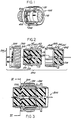
- Figure 2 illustrates a cross-sectional, exploded view of first and second electrical connector members positioned along an axis for mating into (or out of) an electrical connector assembly 800 according to the present invention.
- the electrical connector assembly 800 comprises the first connector member 100 (here considered as the receptacle), the second connector member 200 (here considered as the plug) and the coupling ring 300 about to be mounted by a retaining ring 500 to the first connector member 100 for connecting the first and second connector members together.
- Typical components of the first connector member 100 includes one or more female-type electrical (socket) contacts 130 retained within the shell 101 by one or more inserts 110 and 120.
- the first connector member shell 101 includes a rear portion 102 which is threaded for receiving a moisture sealing and/or strain relief nut (not shown) and a forward portion 103 which includes one or more axially extending projections or keys 104 for orienting the first shell 101 with respect to the second shell 201.
- the socket contacts 130 are mounted within passages 111 disposed in and extending through the insert 110.
- the first shell 101 includes an outer periphery having a medial enlargement or shoulder 140 radially disposed thereabout and on which a plurality of engageable detents in the form of ratchet teeth 141 extend therearound. These engageable detents are shown best in Figure 6.
- the second (plug) connector member 200 includes one or more male-type electrical (pin) contacts 230 that mate with the corresponding socket contacts 130 disposed in the first connector member 100, each of the pin contacts 230 being retained in a respective passage 211 extending through an insert 210 secured to the second shell 201.
- the second shell 201 includes one or more axially extending recesses or keyways 204 for receiving the respective keys 104 disposed on the first shell 101.
- the second shell includes a mateable forward portion 203 having external coupling threads provided thereon and a rearward portion 202.
- the coupling ring 300 is mounted over the rear portion 102 of the first connector member 100 with the medial enlargement 140 providing a forward stop for the coupling ring 300.
- a snap ring 500 when mounted in a groove 150 on the first shell, limits rearward movement of the assembled coupling ring and retains the coupling ring onto the rear portion of the first shell whereby the coupling ring is constrained only to rotate.
- the coupling ring includes internal threads 310 which are adapted to mate with the external threads on the forward portion of the second shell 201 to couple the first and second connector members 100, 200 and their respective contacts 130, 230 together in mated relation.
- the spring member 400 is mounted by a pin 600 toward the rear of and within an undercut portion 320 of the coupling ring.
- Figure 3 shows the first and second connector members 100, 200 assembled and mated and coupled together by the coupling ring 300, the internal threads of the coupling ring threadably engaged with the external threads disposed about the shell 201 of connector member 200.
- One pin contact 230 is shown inserted in the socket 130 to complete an electrical interconnection.
- FIG. 4 is an enlarged plan view of the spring member 400.
- the spring member is "gull-shaped" and comprises a central portion 410 having a longitudinally extending mid-way groove 411 and a pair of wing members 420, 430 extending outwardly therefrom.
- Each wing member includes a first portion or strip 421, 431, to which is superposed a second portion or strip 422, 432, each of the first portions 421, 431 having thereon and extending therefrom a medial projection 440 for engaging one of the teeth or detents 141 disposed around the shell of the first connector member.
- each wing is stamped from a sheet of metal and formed into the desired shape. The two wings generally subtend an angle of about 90°.
- each "wing” could have a “looped” end portion 423, 433, the loop being defined when the continuous portion of metal stock having top and bottom faces is folded back about 180° and onto itself.
- one portion of the bottom face superposes (confronts) another portion of the bottom face, and the top face defines a radially inward or forward surface 424, 434 which faces the detent teeth 141 and a radially outward or rearward surface 426, 436 which faces the interior surface of the coupling ring undercut 320.
- Figure 5 shows the medial projection 440 as being an enlarged dimple or tooth-like shaped projection.
- FIG. 6 shows the coupling ring 300 cut-away and the gull-shaped leaf spring 400 mounted therein. Two such springs are provided, only one being shown by the cut away. Both of the springs are symmetrically shaped and they are diametrically disposed at approximately 180 degrees one from the other.
- Each spring 400 is mounted within the undercut portion 320 of the coupling ring 300 by the pin 600 which extends through a stepped hole 331 in a wall 330 of the coupling ring.
- each of the medial dimples 440 engage a detent (gear tooth) 141 on the first connector member shell 101.
- the dimple or tooth 440 extends from the forward surface 424, 434 radially inward from an imaginary straight line drawn between the ends of the wing and towards the shell. Each of the wing loop end portions is biased to freely ride on the interior surface of the coupling ring undercut.
- Figure 7 shows a fragmentary cut-away view of the coupling ring 300 and the spring mounted in the undercut 320 with the pin 600 securing the central portion 410 to the ring and the distal free ends 425, 435 of each wing 420, 430 being biased against the interior wall of the undercut.
- Figure 8 shows the securement of the spring member to the coupling nut.
- a stepped spring retaining pin 600 having head 601 and shank 602 portions is interference or press fit in the stepped-hole 331 which limits the inward movement of the pin into the coupling ring.
- the pin serves to provide a snug or slip-fit for the spring 400 and provide a certain amount of fixed-free flexural movement of the wings during the rotation of the coupling ring.
- the interference fit eliminates the problem of burrs or metal scraps from entering the connector.
- the "wing members” are intended to be “leaf springs” wherein a first member or strip is in superposed relation with a second member or strip, the strips serving to increase the stiffness of the spring, which in turn increases the spring load or bias of the tooth against a detent, thereby retarding rotation of the coupled assembly.
- a wing could be formed by folding a continuous sheet of resilient material over upon itself, as disclosed herein, or by laminating two resilient strips together, one on top of the other by bonding.
- Use of a spring as disclosed and having two wings has unexpected advantages. First, if due to vibration, should one tooth 440 of one wing happen to be forced out from engagement with its detent, the other tooth could still be biased into engagement with its detent. If both teeth 440 have outwardly directed radial forces acting on them, the reaction forces are shouldered by the central portion 340 of the coupling ring and not on the pin.
Description
- The present invention relates to an electrical connector assembly of the type having a pair of mateable cylindrical shells secured together by a rotatable coupling ring and comprising an improved anti-decoupling mechanism that retains the coupled electrical connector assembly in its mated state against vibration forces which would tend to decouple the assembly.
- There is a continuing need to improve electrical connectors to meet rigid performance standards imposed by severe environmental requirements established by aerospace applications. During mating and unmating, electrical connectors should be easily and quickly coupled and decoupled with the use of reasonable forces. Once mated and in use, however, connector assemblies must remain connected despite vibrational and/or other forces which might be applied to the connector assembly and which might tend to uncouple the connectors.
- Several prior art patents have addressed themselves directly or indirectly to the problem of maintaining an assembled pair of cylindrical electrical connectors together. An approach disclosed by US-A-2 984 811 to Hennessey, et al. includes providing one connector member with a plurality of spaced bayonets which locate within similarly spaced detents carried by a coupling nut when the assembly is fully mated. A prior art patent to Paoli, US-A-3 971 614 discloses interlocking splines. US-A-2 784 385 to Ennis discloses an outer sleeve being provided with a series of exposed teeth and a spring member attached to a fixed flight to engage these teeth. US-A-3 784 966 to Clark shows a spring element engaging one of three recesses. These prior art systems for retarding decoupling had the disadvantage of either being unreliable, difficult to make or prone to failure.
- Another approach is typified by US-A-4 109 990 to Waldron et al. where a single spring member is disposed within a recess of a coupling nut and the spring includes an inwardly extending projection to engage ratchet teeth on the connector member to be mated. While suitable in many applications, the spring member did not always provide positive and secure engagement with the ratchet teeth and the restraining torques sometimes were not sufficient to prevent the decoupling under vibration. Mounting of the four pins shown by Waldron et al. required substantial cost to drill the holes and, during interference fitment of the pins into the holes, caused burrs and/or flakes to enter the connector.
- Still a further approach is wherein one end of a spring loaded detent pin is slidably mounted in a radial bore of a coupling nut and the other end biased into engagement with a connector detent.
- There is a continuing need to provide electrical connector assemblies with a mechanism that prevents accidental decoupling, that is cheap, reliable, easy to make and assemble and which secures the assembly together.
- To this end, the invention proposes an electrical connector assembly having anti-decoupling mechanism including a first electrical connector having a shell and an electrical contact mounted therein, a second electrical connector having a second shell and an electrical contact mounted therein and mateable with the contact in the first shell, a coupling ring having an inner wall and rotatably mounted on the first shell for selectively coupling or decoupling said first and second shells longitudinally together in the mated relationship, means for retarding rotational movement of the coupling ring with respect to the shells, characterized in that said retarding means comprises a shoulder radially outwardly disposed about the first shell with the surface thereof facing toward the inner wall of the coupling ring, said radially disposed shoulder being provided with engageable detents and a gull-shaped detent-engaging spring member having a central portion and a pair of wings extending therefrom, the central portion being mounted to the coupling ring and the wings having free ends disposed adjacent the inner wall of the coupling ring, each of said wings including first and second resilient members each, the first member being secured to and disposed radially inward of the respective second member and having a surface facing in the direction of said engageable detents, the said surface of each first member including a mediate portion that projects inwardly of the coupling ring in a radial direction from an imaginary straight line between the ends of the wing first member and towards the first shell for engaging the detents to retard rotational movement.
- Accordingly, the invention provides a quickly connectable and disconnectable electrical connector assembly that provides an adequate resistance to uncoupling forces and prevents unauthorized or accidental decoupling, thereby overcoming the limitations of the prior art systems.
- In a preferred embodiment of the invention, there is a first electrical connector including a shell having electrical contacts mounted therein, a second electrical connector including a second shell having external screw threads disposed therearound and electrical contacts mounted therein and mateable with the contacts in the first shell, a coupling ring rotatably mounted on the first shell for selectively coupling or decoupling the first and second shells and having internal threads connectable with the external threads on the second shell for connecting the first and second shells together in mated relationship and means for retarding the rotational movement of the coupling ring with respect of the shells when mated. The retarding means comprise at least one "gull-shaped" leaf spring member characterized by an arcuate grooved central portion adapted to be mounted to the coupling ring, a pair of "wing members" extending outwardly from the central portion to ends which rest freely on an interior wall portion of the coupling ring and a medial enlargement (dimple) or tooth member extending inwardly from each wing for selectively engaging one of a plurality of ratchet teeth circumposed around the first shell. Preferably each of the "wings" are formed by folding a sheet of metal stock over onto itself to define first and second superposed strips. The spring member is made of a resilient yieldable material which permits each wing to flex radially inwardly and outwardly but yet with the "leaf" construction to provide adequate resistance to retrograde rotation and prevent disengagement of the coupling ring. Preferably two such spring members are mounted at diametrically opposite locations in the coupling ring. Two "gull-shaped" spring members so placed assure that due to vibration if one of the wings on each spring disengages from its ratchet tooth, then the other wing will still be in engagement with another ratchet tooth and that a pair of off-set wings will still act to provide decoupling motion.
- Accordingly, it is an advantage of this invention to provide an improved electrical connector that is cheap, reliable, easy to make and assemble, which retains mated electrical connectors in coupled condition and prevents accidental disassembly thereof through vibration.
- Another advantage of this invention is to provide an anti-decoupling mechanism for use with cylindrical electrical connectors to be coupled together into an assembly which substantially increases the amount of torque necessary to uncouple the assembly over that achieved in the prior art without redesign of existing connector members.
- Still a further advantage is to provide a spring member which can be easily attached by a pin to a coupling ring of a cylindrical connector without burrs or flakes from attachment entering the connector.
- Still a further advantage is to provide a securement of the spring member which does not permit environmental moisture or other materials and contaminants to enter the connector portion.
- Yet another advantage of this invention is the provision of a spring member which distributes spring reaction forces about a connectable connector member.
- Another advantage of the invention is the provision of a spring having a pair of superposed strips, for increasing the stiffness and the bias force available to be applied against a connector from rotating.
- A more specific advantage of the invention is to provide a one-piece spring member having folded over spring arms provided with enlarged medial portions and defining a pair free ends in contact with a connector assembly member.
- The above and other advantages and features of the present invention will become apparent from the following detailed description, taken in conjunction with the accompanying drawings wherein:
- Figure 1 is a perspective view of a connector member partially cut-away to show an anti-decoupling mechanism of the present invention;
- Figure 2 is an exploded sectional view of a pair of mateable connector members and a coupling ring about to be assembled into an electrical connector assembly;
- Figure 3 is a sectional cut-away view of the connector members of Figure 2 mated and coupled together to form the electrical connector assembly;
- Figure 4 is a plan view of a spring member for a connector assembly according to the present invention;
- Figure 5 shows a forward face of the spring member taken along lines V-V of Figure 4 and showing a medial tooth shaped dimple;
- Figure 6 is a partially cut-away view of the coupling ring taken along lines VI-VI of the connector assembly of Figure 3 showing the spring member;
- Figure 7 is a fragmented section view of the coupling ring taken along lines VII-VII of Figure 6;
- Figure 8 is a section view taken along lines VIII-VIII of Figure 6 showing securement of the spring member to the coupling ring.
- Referring now to the drawings, Figure 1 illustrates partially in perspective and cut-away a mateable
first connector member 100 incorporating ananti-decoupling device 400. Depending on whether the first connector member retains mateable male (pin) or female (socket) contacts, the first connector member would be referred to respectively as a plug or a receptacle connector. Theconnector member 100 shown is a receptacle and comprises afirst shell 101, acontact retaining insert 110 disposed in the shell, acoupling ring 300 rotatably disposed about the shell and thespring member 400 mounted to the coupling ring by apin 600. - Figure 2 illustrates a cross-sectional, exploded view of first and second electrical connector members positioned along an axis for mating into (or out of) an
electrical connector assembly 800 according to the present invention. Theelectrical connector assembly 800 comprises the first connector member 100 (here considered as the receptacle), the second connector member 200 (here considered as the plug) and thecoupling ring 300 about to be mounted by aretaining ring 500 to thefirst connector member 100 for connecting the first and second connector members together. Typical components of thefirst connector member 100 includes one or more female-type electrical (socket)contacts 130 retained within theshell 101 by one ormore inserts connector member shell 101 includes arear portion 102 which is threaded for receiving a moisture sealing and/or strain relief nut (not shown) and aforward portion 103 which includes one or more axially extending projections or keys 104 for orienting thefirst shell 101 with respect to thesecond shell 201. Thesocket contacts 130 are mounted within passages 111 disposed in and extending through theinsert 110. Thefirst shell 101 includes an outer periphery having a medial enlargement or shoulder 140 radially disposed thereabout and on which a plurality of engageable detents in the form ofratchet teeth 141 extend therearound. These engageable detents are shown best in Figure 6. - The second (plug)
connector member 200 includes one or more male-type electrical (pin) contacts 230 that mate with thecorresponding socket contacts 130 disposed in thefirst connector member 100, each of the pin contacts 230 being retained in a respective passage 211 extending through aninsert 210 secured to thesecond shell 201. Thesecond shell 201 includes one or more axially extending recesses orkeyways 204 for receiving the respective keys 104 disposed on thefirst shell 101. The second shell includes a mateableforward portion 203 having external coupling threads provided thereon and arearward portion 202. - The
coupling ring 300 is mounted over therear portion 102 of thefirst connector member 100 with the medial enlargement 140 providing a forward stop for thecoupling ring 300. Asnap ring 500, when mounted in agroove 150 on the first shell, limits rearward movement of the assembled coupling ring and retains the coupling ring onto the rear portion of the first shell whereby the coupling ring is constrained only to rotate. The coupling ring includesinternal threads 310 which are adapted to mate with the external threads on the forward portion of thesecond shell 201 to couple the first andsecond connector members respective contacts 130, 230 together in mated relation. - The
spring member 400 is mounted by apin 600 toward the rear of and within anundercut portion 320 of the coupling ring. - Figure 3 shows the first and
second connector members coupling ring 300, the internal threads of the coupling ring threadably engaged with the external threads disposed about theshell 201 ofconnector member 200. One pin contact 230 is shown inserted in thesocket 130 to complete an electrical interconnection. - Figure 4 is an enlarged plan view of the
spring member 400. The spring member is "gull-shaped" and comprises acentral portion 410 having a longitudinally extendingmid-way groove 411 and a pair ofwing members strip strip first portions medial projection 440 for engaging one of the teeth ordetents 141 disposed around the shell of the first connector member. Preferably, each wing is stamped from a sheet of metal and formed into the desired shape. The two wings generally subtend an angle of about 90°. Depending on the application, each "wing" could have a "looped"end portion forward surface detent teeth 141 and a radially outward orrearward surface - Figure 5 shows the
medial projection 440 as being an enlarged dimple or tooth-like shaped projection. - Figure 6 shows the
coupling ring 300 cut-away and the gull-shapedleaf spring 400 mounted therein. Two such springs are provided, only one being shown by the cut away. Both of the springs are symmetrically shaped and they are diametrically disposed at approximately 180 degrees one from the other. Eachspring 400 is mounted within the undercutportion 320 of thecoupling ring 300 by thepin 600 which extends through a steppedhole 331 in awall 330 of the coupling ring. When the leaf spring is mounted in the undercut 320 of the coupling ring, each of themedial dimples 440 engage a detent (gear tooth) 141 on the firstconnector member shell 101. The dimple ortooth 440 extends from theforward surface - Figure 7 shows a fragmentary cut-away view of the
coupling ring 300 and the spring mounted in the undercut 320 with thepin 600 securing thecentral portion 410 to the ring and the distal free ends 425, 435 of eachwing - Figure 8 shows the securement of the spring member to the coupling nut. A stepped
spring retaining pin 600 havinghead 601 andshank 602 portions is interference or press fit in the stepped-hole 331 which limits the inward movement of the pin into the coupling ring. The pin serves to provide a snug or slip-fit for thespring 400 and provide a certain amount of fixed-free flexural movement of the wings during the rotation of the coupling ring. The interference fit eliminates the problem of burrs or metal scraps from entering the connector. - Broadly speaking, the "wing members" are intended to be "leaf springs" wherein a first member or strip is in superposed relation with a second member or strip, the strips serving to increase the stiffness of the spring, which in turn increases the spring load or bias of the tooth against a detent, thereby retarding rotation of the coupled assembly. Such a wing could be formed by folding a continuous sheet of resilient material over upon itself, as disclosed herein, or by laminating two resilient strips together, one on top of the other by bonding. Use of a spring as disclosed and having two wings has unexpected advantages. First, if due to vibration, should one
tooth 440 of one wing happen to be forced out from engagement with its detent, the other tooth could still be biased into engagement with its detent. If bothteeth 440 have outwardly directed radial forces acting on them, the reaction forces are shouldered by thecentral portion 340 of the coupling ring and not on the pin. - Further, by provision of such a pin and spring member, a given or known vibration environment would permit the user to interchange spring members (having weaker/stronger characteristics) without redesigning the entire connector assembly.
- While a preferred embodiment of the invention has been disclosed, it will be apparent to those skilled in the art that many changes may be made to the invention within the spirit as set forth in the preceding description without departing from the scope of the claims. For example, springs having a plastic portion engaging the metal teeth, may be desirable. In some instances, the substitution of plastic for the ratchet teeth may be advisable, which would allow the use of a metal spring.
Claims (6)
Applications Claiming Priority (2)
| Application Number | Priority Date | Filing Date | Title |
|---|---|---|---|
| US147699 | 1980-05-07 | ||
| US06/147,699 US4648670A (en) | 1980-05-07 | 1980-05-07 | Electrical connector assembly having anti-decoupling mechanism |
Publications (3)
| Publication Number | Publication Date |
|---|---|
| EP0039640A2 EP0039640A2 (en) | 1981-11-11 |
| EP0039640A3 EP0039640A3 (en) | 1982-01-06 |
| EP0039640B1 true EP0039640B1 (en) | 1984-08-22 |
Family
ID=22522566
Family Applications (1)
| Application Number | Title | Priority Date | Filing Date |
|---|---|---|---|
| EP81400691A Expired EP0039640B1 (en) | 1980-05-07 | 1981-04-30 | Electrical connector assembly having anti-decoupling mechanism |
Country Status (5)
| Country | Link |
|---|---|
| US (1) | US4648670A (en) |
| EP (1) | EP0039640B1 (en) |
| JP (1) | JPS573380A (en) |
| CA (1) | CA1163337A (en) |
| DE (1) | DE3165643D1 (en) |
Cited By (1)
| Publication number | Priority date | Publication date | Assignee | Title |
|---|---|---|---|---|
| EP3528346A1 (en) | 2018-02-16 | 2019-08-21 | Connecteurs Electriques Deutsch | Electrical connector assembly |
Families Citing this family (25)
| Publication number | Priority date | Publication date | Assignee | Title |
|---|---|---|---|---|
| EP0189343A3 (en) * | 1985-01-22 | 1988-11-30 | Itt Industries, Inc. | Radial force anti-decoupling connector |
| FR2587552B1 (en) * | 1985-09-13 | 1987-12-18 | Socapex | ELECTRICAL CONNECTOR COMPRISING AN ANTI-LOCKING DEVICE |
| US4808123A (en) * | 1987-02-04 | 1989-02-28 | Diverse Termination Products, Inc. | Self-locking strain-relief end bell for electrical connector assembly |
| US4914060A (en) * | 1989-03-17 | 1990-04-03 | Seas James A | Connector for antennas and coaxial cable |
| JPH0766838B2 (en) * | 1989-09-25 | 1995-07-19 | 株式会社中部プラントサービス | Explosion-proof plug connector |
| US5082454A (en) * | 1989-09-28 | 1992-01-21 | Joslyn Corporation | Two-piece retaining ring |
| US5046964A (en) * | 1989-10-10 | 1991-09-10 | Itt Corporation | Hybrid connector |
| US5145394A (en) * | 1991-10-03 | 1992-09-08 | G & H Technology, Inc. | Anti-rotation assembly for interconnect devices |
| US5496189A (en) | 1994-10-19 | 1996-03-05 | The Whitaker Corporation | Electrical connector assembly including improved decoupling retardation mechanism |
| US5959828A (en) * | 1996-07-16 | 1999-09-28 | Hydraflow | Coupling with insulated flanges |
| US5786976A (en) * | 1996-07-16 | 1998-07-28 | Hydraflow | Coupling with hard metallic ductile conductive coating |
| FR2766974A1 (en) * | 1997-07-30 | 1999-01-29 | Socapex Amphenol | ELECTRICAL CONNECTION DEVICE |
| WO2001077535A1 (en) * | 2000-04-08 | 2001-10-18 | Witte-Velbert Gmbh & Co. Kg | Connecting device |
| US6918816B2 (en) * | 2003-01-31 | 2005-07-19 | Adc Telecommunications, Inc. | Apparatus and method for polishing a fiber optic connector |
| DE102005026398B4 (en) * | 2005-06-08 | 2009-01-29 | Lapp Engineering & Co. | Rotatable connector assembly with latching |
| FR2925234B1 (en) * | 2007-12-14 | 2010-01-22 | Radiall Sa | CONNECTOR WITH ANTI-UNLOCKING SYSTEM |
| US9217524B2 (en) | 2011-11-23 | 2015-12-22 | Parker-Hannifin Corporation | Coupling lock mechanism |
| US8960726B2 (en) | 2011-11-23 | 2015-02-24 | Parker-Hannifin Corporation | Coupling lock mechanism |
| US8690595B2 (en) * | 2012-06-25 | 2014-04-08 | Cooper Technologies Company | Squid connector with coupling feature |
| CA2845372A1 (en) * | 2013-03-13 | 2014-09-13 | Amphenol Corporation | Anti-decoupling member for connector component |
| US9397441B2 (en) * | 2013-03-15 | 2016-07-19 | Cinch Connections, Inc. | Connector with anti-decoupling mechanism |
| US9640902B2 (en) * | 2014-07-03 | 2017-05-02 | Sercel | Stress relief device for a connector and a connector equipped with such stress relief device |
| US9531120B2 (en) | 2014-09-04 | 2016-12-27 | Conesys, Inc. | Circular connectors |
| US9666973B1 (en) * | 2016-06-10 | 2017-05-30 | Amphenol Corporation | Self-locking connector coupling |
| DE102017118014B3 (en) | 2017-08-08 | 2018-07-12 | Phoenix Contact Gmbh & Co. Kg | Connector part with a locking element |
Family Cites Families (15)
| Publication number | Priority date | Publication date | Assignee | Title |
|---|---|---|---|---|
| FR469020A (en) * | 1913-09-23 | 1914-07-22 | Morris Jacobs | Automatic clamping and locking devices for all types of threaded parts, nuts and bolts |
| FR635045A (en) * | 1927-05-25 | 1928-03-05 | Nut lock | |
| US2926547A (en) * | 1957-06-04 | 1960-03-01 | Bendix Aviat Corp | Pawl and ratchet mechanism |
| FR1195451A (en) * | 1958-04-28 | 1959-11-17 | Abg | Elastic locking device for sockets |
| US3650157A (en) * | 1959-03-16 | 1972-03-21 | Controls Co Of America | Timer |
| US3142149A (en) * | 1962-05-16 | 1964-07-28 | Gen Electric | Drive mechanism |
| US3892458A (en) * | 1973-04-04 | 1975-07-01 | Deutsch Co Elec Comp | Coupling for electrical connector or the like |
| US4030798A (en) * | 1975-04-11 | 1977-06-21 | Akzona Incorporated | Electrical connector with means for maintaining a connected condition |
| US4066315A (en) * | 1976-07-26 | 1978-01-03 | Automation Industries, Inc. | Electrical connector with arcuate detent means |
| US4109990A (en) * | 1977-05-26 | 1978-08-29 | The Bendix Corporation | Electrical connector assembly having anti-decoupling mechanism |
| US4152039A (en) * | 1977-10-21 | 1979-05-01 | Akzona Incorporated | Non-decoupling electrical connector |
| US4165910A (en) * | 1977-10-25 | 1979-08-28 | Bunker Ramo Corporation | Electrical connector |
| US4268103A (en) * | 1979-02-02 | 1981-05-19 | The Bendix Corporation | Electrical connector assembly having anti-decoupling mechanism |
| US4239314A (en) * | 1979-04-11 | 1980-12-16 | Bunker Ramo Corporation | Electrical connector |
| US4272144A (en) * | 1979-12-18 | 1981-06-09 | The Bendix Corporation | Spring loaded anti-rotation device for electrical connectors |
-
1980
- 1980-05-07 US US06/147,699 patent/US4648670A/en not_active Expired - Lifetime
-
1981
- 1981-04-08 CA CA000375025A patent/CA1163337A/en not_active Expired
- 1981-04-30 EP EP81400691A patent/EP0039640B1/en not_active Expired
- 1981-04-30 DE DE8181400691T patent/DE3165643D1/en not_active Expired
- 1981-05-07 JP JP6775481A patent/JPS573380A/en active Granted
Cited By (2)
| Publication number | Priority date | Publication date | Assignee | Title |
|---|---|---|---|---|
| EP3528346A1 (en) | 2018-02-16 | 2019-08-21 | Connecteurs Electriques Deutsch | Electrical connector assembly |
| US10938152B2 (en) | 2018-02-16 | 2021-03-02 | Connecteurs Electriques Deutsch | Electrical connector assembly |
Also Published As
| Publication number | Publication date |
|---|---|
| DE3165643D1 (en) | 1984-09-27 |
| JPS573380A (en) | 1982-01-08 |
| CA1163337A (en) | 1984-03-06 |
| JPH0311062B2 (en) | 1991-02-15 |
| EP0039640A2 (en) | 1981-11-11 |
| US4648670A (en) | 1987-03-10 |
| EP0039640A3 (en) | 1982-01-06 |
Similar Documents
| Publication | Publication Date | Title |
|---|---|---|
| EP0039640B1 (en) | Electrical connector assembly having anti-decoupling mechanism | |
| US4109990A (en) | Electrical connector assembly having anti-decoupling mechanism | |
| EP0080930A2 (en) | Electrical connector assembly | |
| CA1070792A (en) | Electrical connector and frequency shielding means therefor and method of making same | |
| JP3559759B2 (en) | Detachment prevention equipment for electrical connectors | |
| US4484790A (en) | Anti-decoupling device for an electrical connector | |
| US3892458A (en) | Coupling for electrical connector or the like | |
| WO1986004690A1 (en) | Coupling mechanism for connectors | |
| US4154496A (en) | Coupling assembly for resilient electrical connector components | |
| JPS6351355B2 (en) | ||
| US4497530A (en) | Electrical connector having a coupling indicator | |
| US4462652A (en) | Coupling nut for an electrical connector | |
| US4500154A (en) | Electrical connector assembly having an anti-decoupling device | |
| US4531801A (en) | Plug and receptacle connector locking means | |
| GB2109645A (en) | Self-locking electrical connector | |
| US5496189A (en) | Electrical connector assembly including improved decoupling retardation mechanism | |
| US4544224A (en) | Self-locking electrical connector | |
| US4457572A (en) | Coupling nut for an electrical connector | |
| US4645282A (en) | Releasing electrical connector assembly | |
| US4255008A (en) | Electrical connector assembly having anti-decoupling device | |
| US4448470A (en) | Coupling member and an electrical connector | |
| US4506942A (en) | Anti-decoupling mechanism for electrical connector | |
| US4478474A (en) | Coupling nut for an electrical connector | |
| US4695109A (en) | Quick release connector | |
| CN110939802A (en) | Screwed connection piece screwing assembly and connector |
Legal Events
| Date | Code | Title | Description |
|---|---|---|---|
| PUAI | Public reference made under article 153(3) epc to a published international application that has entered the european phase |
Free format text: ORIGINAL CODE: 0009012 |
|
| PUAL | Search report despatched |
Free format text: ORIGINAL CODE: 0009013 |
|
| 17P | Request for examination filed |
Effective date: 19810505 |
|
| AK | Designated contracting states |
Designated state(s): DE FR GB IT |
|
| AK | Designated contracting states |
Designated state(s): DE FR GB IT |
|
| ITF | It: translation for a ep patent filed |
Owner name: ING. ZINI MARANESI & C. S.R.L. |
|
| GRAA | (expected) grant |
Free format text: ORIGINAL CODE: 0009210 |
|
| AK | Designated contracting states |
Designated state(s): DE FR GB IT |
|
| REF | Corresponds to: |
Ref document number: 3165643 Country of ref document: DE Date of ref document: 19840927 |
|
| ET | Fr: translation filed | ||
| PLBE | No opposition filed within time limit |
Free format text: ORIGINAL CODE: 0009261 |
|
| STAA | Information on the status of an ep patent application or granted ep patent |
Free format text: STATUS: NO OPPOSITION FILED WITHIN TIME LIMIT |
|
| 26N | No opposition filed | ||
| ITTA | It: last paid annual fee | ||
| PGFP | Annual fee paid to national office [announced via postgrant information from national office to epo] |
Ref country code: DE Payment date: 19960430 Year of fee payment: 16 |
|
| PG25 | Lapsed in a contracting state [announced via postgrant information from national office to epo] |
Ref country code: DE Free format text: LAPSE BECAUSE OF NON-PAYMENT OF DUE FEES Effective date: 19980101 |
|
| PGFP | Annual fee paid to national office [announced via postgrant information from national office to epo] |
Ref country code: GB Payment date: 19980312 Year of fee payment: 18 |
|
| PGFP | Annual fee paid to national office [announced via postgrant information from national office to epo] |
Ref country code: FR Payment date: 19980408 Year of fee payment: 18 |
|
| PG25 | Lapsed in a contracting state [announced via postgrant information from national office to epo] |
Ref country code: GB Free format text: LAPSE BECAUSE OF NON-PAYMENT OF DUE FEES Effective date: 19990430 |
|
| GBPC | Gb: european patent ceased through non-payment of renewal fee |
Effective date: 19990430 |
|
| PG25 | Lapsed in a contracting state [announced via postgrant information from national office to epo] |
Ref country code: FR Free format text: LAPSE BECAUSE OF NON-PAYMENT OF DUE FEES Effective date: 19991231 |
|
| REG | Reference to a national code |
Ref country code: FR Ref legal event code: ST |