EP0039480A2 - Fluiddrucksteuervorrichtung - Google Patents
Fluiddrucksteuervorrichtung Download PDFInfo
- Publication number
- EP0039480A2 EP0039480A2 EP81103254A EP81103254A EP0039480A2 EP 0039480 A2 EP0039480 A2 EP 0039480A2 EP 81103254 A EP81103254 A EP 81103254A EP 81103254 A EP81103254 A EP 81103254A EP 0039480 A2 EP0039480 A2 EP 0039480A2
- Authority
- EP
- European Patent Office
- Prior art keywords
- valve
- cam
- item
- respect
- support
- Prior art date
- Legal status (The legal status is an assumption and is not a legal conclusion. Google has not performed a legal analysis and makes no representation as to the accuracy of the status listed.)
- Withdrawn
Links
Images

Classifications
-
- G—PHYSICS
- G05—CONTROLLING; REGULATING
- G05D—SYSTEMS FOR CONTROLLING OR REGULATING NON-ELECTRIC VARIABLES
- G05D16/00—Control of fluid pressure
- G05D16/04—Control of fluid pressure without auxiliary power
- G05D16/06—Control of fluid pressure without auxiliary power the sensing element being a flexible membrane, yielding to pressure, e.g. diaphragm, bellows, capsule
- G05D16/063—Control of fluid pressure without auxiliary power the sensing element being a flexible membrane, yielding to pressure, e.g. diaphragm, bellows, capsule the sensing element being a membrane
- G05D16/0644—Control of fluid pressure without auxiliary power the sensing element being a flexible membrane, yielding to pressure, e.g. diaphragm, bellows, capsule the sensing element being a membrane the membrane acting directly on the obturator
- G05D16/0655—Control of fluid pressure without auxiliary power the sensing element being a flexible membrane, yielding to pressure, e.g. diaphragm, bellows, capsule the sensing element being a membrane the membrane acting directly on the obturator using one spring-loaded membrane
- G05D16/0661—Control of fluid pressure without auxiliary power the sensing element being a flexible membrane, yielding to pressure, e.g. diaphragm, bellows, capsule the sensing element being a membrane the membrane acting directly on the obturator using one spring-loaded membrane characterised by the loading mechanisms of the membrane
-
- F—MECHANICAL ENGINEERING; LIGHTING; HEATING; WEAPONS; BLASTING
- F02—COMBUSTION ENGINES; HOT-GAS OR COMBUSTION-PRODUCT ENGINE PLANTS
- F02D—CONTROLLING COMBUSTION ENGINES
- F02D21/00—Controlling engines characterised by their being supplied with non-airborne oxygen or other non-fuel gas
- F02D21/06—Controlling engines characterised by their being supplied with non-airborne oxygen or other non-fuel gas peculiar to engines having other non-fuel gas added to combustion air
- F02D21/08—Controlling engines characterised by their being supplied with non-airborne oxygen or other non-fuel gas peculiar to engines having other non-fuel gas added to combustion air the other gas being the exhaust gas of engine
-
- F—MECHANICAL ENGINEERING; LIGHTING; HEATING; WEAPONS; BLASTING
- F02—COMBUSTION ENGINES; HOT-GAS OR COMBUSTION-PRODUCT ENGINE PLANTS
- F02M—SUPPLYING COMBUSTION ENGINES IN GENERAL WITH COMBUSTIBLE MIXTURES OR CONSTITUENTS THEREOF
- F02M26/00—Engine-pertinent apparatus for adding exhaust gases to combustion-air, main fuel or fuel-air mixture, e.g. by exhaust gas recirculation [EGR] systems
- F02M26/52—Systems for actuating EGR valves
- F02M26/55—Systems for actuating EGR valves using vacuum actuators
- F02M26/56—Systems for actuating EGR valves using vacuum actuators having pressure modulation valves
-
- G—PHYSICS
- G05—CONTROLLING; REGULATING
- G05D—SYSTEMS FOR CONTROLLING OR REGULATING NON-ELECTRIC VARIABLES
- G05D16/00—Control of fluid pressure
- G05D16/04—Control of fluid pressure without auxiliary power
- G05D16/06—Control of fluid pressure without auxiliary power the sensing element being a flexible membrane, yielding to pressure, e.g. diaphragm, bellows, capsule
- G05D16/063—Control of fluid pressure without auxiliary power the sensing element being a flexible membrane, yielding to pressure, e.g. diaphragm, bellows, capsule the sensing element being a membrane
- G05D16/0636—Control of fluid pressure without auxiliary power the sensing element being a flexible membrane, yielding to pressure, e.g. diaphragm, bellows, capsule the sensing element being a membrane characterised by the loading device of the membrane, e.g. spring
-
- Y—GENERAL TAGGING OF NEW TECHNOLOGICAL DEVELOPMENTS; GENERAL TAGGING OF CROSS-SECTIONAL TECHNOLOGIES SPANNING OVER SEVERAL SECTIONS OF THE IPC; TECHNICAL SUBJECTS COVERED BY FORMER USPC CROSS-REFERENCE ART COLLECTIONS [XRACs] AND DIGESTS
- Y10—TECHNICAL SUBJECTS COVERED BY FORMER USPC
- Y10T—TECHNICAL SUBJECTS COVERED BY FORMER US CLASSIFICATION
- Y10T137/00—Fluid handling
- Y10T137/2278—Pressure modulating relays or followers
- Y10T137/2409—With counter-balancing pressure feedback to the modulating device
Definitions
- the present invention relates to fluid pressure controllers and particularly controllers of the type which provide a regulated output signal when connected to a source of variable fluid pressure and which are responsive to a mechanical input to alter the desired value of the regulated output signal.
- Devices of this type are employed in accessory controls for internal combustion engines in automotive applications where it is desired to provide a regulated and selectively changeable fluid pressure vacuum signal responsive to movement of the engine throttle and also to provide for the completing and the breaking of an electrical circuit at a predetermined position of the mechanical input such as the vehicle throttle position.
- An example of such an application is a vacuum controller which provides a regulated vacuum signal, upon connection to the-vacuum pump source and receives an input from the vehicle throttle to provide changes in the regulated vacuum output signal in accordance with the predetermined scheduled throttle position for actuating an exhaust gas recirculation control valve.
- the electrical circuit which is completed and broken at predetermined throttle position may be employed to actuate and de-actuate an electrically operated transmission shift control mechanism.
- Such devices as that described in the Franz etal application are employed for providing a regulated vacuum signal from varying source, such as a vacuum pump source for use in controlling devices such as transmissions and exhaust gas recirculation valves.
- FIG. 897,604 Another known vacuum signal controller is that described in U.S. Patent Application Serial No. 897,604 filed April 18, 1978, in the name of R. J. Franz and assigned to the assignee of the present invention.
- the Franz device utilizes a rotating cam to vary the preload on a temperature sensitive element operated vacuum modulator valve.
- the present invention provides a fluid pressure signal controller responsive to a mechanical input to vary the level of a regulated fluid pressure signal upon connection of the controller to the source of variable fluid pressure.
- the controller also contains an electrical switching mechanism responsive to the mechanical input to provide making and breaking of an electrical circuit at predetermined positions of the mechanical input.
- the novel controller of the present invention finds particularly useful application in controlling exhaust gas recirculation (BGR) valve for an internal combustion engine and particularly diesel engines having the throttle connected to the fuel supply feed to the combustion chambers for controlling engine speed at any given engine load.
- BGR exhaust gas recirculation
- the controller of the present invention employs a diaphragm actuated pressure-operated force-balance modulator valve responsive to a mechanical preload to provide a regulated fluid pressure output signal of a desired level, irrespective of normal variations in the fluid pressure supply.
- the present controller when employed in the aforementioned diesel engine application. is connected to the vacuum pump for the fluid pressure source, and has a rotary cam adapted for attachment to a rotatable shaft connected directly to the engine fuel injection throttle mechanism.
- the rotatable cam causes linear movement of a slidable cam follower which is connected to a preload spring attached to the modulator valve diaphragm wherein movement of the cam follower varies the preload on the modulator valve diaphragm.
- the preload on the modulator valve diaphragm serves to alter the level of the regulated fluid pressure signal provided at the output of the modulator valve.
- An electrical switch is mounted such that the switch actuator also follows the rotary cam and the rotary cam is operative to effect actuation and deactuation of the switch.
- the rotary cam, cam follower, electrical switch mechanism and modulator valve are mounted to a common body portion.
- the present invention thus provides a solution to the above-described problems with heretofore known rotary cam adjustable vacuum regulator valve assemblies by employing unique structural arrangement wherein the modulator valve is slidably mounted on the base or body. A threaded ring is provided, rotation of which adjusts the position of the modulator valve with respect to the body for adjusting the initial preload on the diaphragm bias spring thereby permitting ease of calibration of the controller.
- the present invention thus provides a novel controller for providing a regulated fluid pressure signal from a variable source of fluid pressure and an electrical switching function, wherein the level of the regulated fluid pressure signal and the point of actuation of the switching function are determined by the position of a rotatable cam provided on the controller.
- the controller employs a diaphragm actuated pressure operated force-balance modulator valve, the bias of which is varied in service from the rotary cam connected to a preload spring attached to the diaphragm.
- the modulator valve is slidably adjusted with respect to the cam for readily adjusting the calibration by rotation of a ring threadedly engaging the modulator valve for slidably adjusting the valve position with respect to the controller body. Movement of the valve position on the controller body effects a change in the length of the bias spring which in turn changes the calibration of the modulator valve output signal for any given position of the input cam.
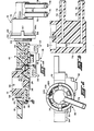
- the controller 10 of the present invention is shown as having a body or base 12 with a rotary cam indicated generally at 14 mounted thereon on the upper face thereof and a modulator valve assembly indicated generally at 16 slidably mounted at the right-hand end thereof with respect to Figure 1.
- An electrical switching mechanism indicated generally at 18 is provided on the under surface of the body and has electrical leads 20, 22 provided thereon for attachment to a circuit to be switched.
- the body 12 has a bore 24 formed therein with an annular shoulder 26 formed in the bore.
- the upper surface of a flange 28 provided on rotary cam 14 is slidably registered against shoulder 26.
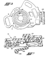
- Cam 14 is retained in bore 24 by a cover 30 retained on the body 12 by suitable fastening expedients as, for example locking tabs 31 (see Fig. 4) and a self-tapping screw 32.
- Cover 30 has a bore 34 provided therein and the cam 14 has a pilot 36 journaled in bore 34 for guiding and locating the cam flange 28 on the annular shoulder 26.
- the undersurface 38 of the cum flange 28 is shown as having a recess 40 formed therein with a variable radius wall portion forming a cam surface 42.
- a cam follower 44 is slidably received in a recess 46 provided in the undersurface of body 12 and is sliuably guided therein and retained by the upper surface 48 of cover 30.
- the left end of cam follower 44 in Figure 1 has an upwardly extending portion with a cam following surface 50 formed thereon which registers against the cam surface 42 of the rotary cam.
- the right-hand end of cam follower 44 also has an upwardly extending portion 52 which has an aperture provided therein with one end 54 of - a tension spring received in the aperture and retained therein by deformation of the end of the spring.
- a torsion spring 56 is received over the cylindrical surface 58 of cam 14, with one end 60 of spring 56 registered in a notch 62 provided in the body 12 and the other end 64 of spring 56 bent at right angles to the coil of the spring and received in an aperture 66 formed in the cylindrical surface 58 of the cam.
- cam 14 has a pair of arcuately shaped recesses 6 7 provided therein, the ends of which are adapted to receive diametrically thereacross a torsional driving member therein as, for example, a flat blade member (not shown).
- a torsional driving member (not shown) engaging the arcuate recesses 67
- cam follower 44 is moved in a horizontal direction to vary the position of spring end 54.
- the body 12 has, at the right end thereof, with respect to Figure 1, a threaded portion 68 for receiving adjustably thereon the modulator valve 16 as will be hereinafter described in greater detail.
- the rotary cam 58, body 12, cam follower 44, and cover 30 are made of plastic material suitable for service in a vehicle engine compartment environment.
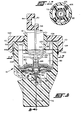
- the modulator valve 16 will now be described in greater detail as having a body 70 having provided thereon a vacuum source nipple 72 having therein a vacuum source port 74 and spaced therefrom a signal output nipple 76 having therein a signal port 78.
- the nipples 72 and 76 are adapted to have received over the ends thereof a suitable hose for connection to, respectively, a source of vacuum and a vacuum operated device to be controlled.
- the upper portion of body 70 has a cylindrical cavity 80 formed therein, which cavity has received and retained therein a diaphragm vent-valve subassembly indicated generally at 82 received and retained therein.
- the vent valve subassembly 82 includes a vent seat member 84 having the lower end 55 of the tension spring received therein through a transverse aperture. The vent seat member 84 is thus biased in an upward direction with respect to Figure 5 by the end 55 of the spring.
- the vent valve subassembly 82 includes a movable valve member 86 having at its upper end a vent valve seating surface 86a and at its lower end a vacuum valve surface 86b.
- Valve body 70 has a signal chamber 88 formed therein below cavity 80 which chamber 88 has a central passage 90 provided therein communicating with vacuum supply ports 74.
- Passage 90 has at the upper end thereof a vacuum valve seating surface 92 against which valve surface 86b is moved to provide a valving action to control fluid flow between chamber 88 and supply port 74 .
- passage 94 is provided in valve body 70 which communicates signal chamber 88 with signal output port 76.
- the diaphragm vent-valve subassembly 82 includes a resilient annular diaphragm 96, preferably formed of a suitable elastomeric material, having its outer periphery sealed therearound against body 70, with its inner periphery sealed about vent seat member 84 to complete the upper wall of signal chamber 88.
- the body 70 is molded of a plastic material suitable for vehicle engine compartment service.
- diaphragm 96 responsive to the difference in pressure in cavity 80 thereabove, and signal chamber 88 therebelow, causes vent seat member 84 to move vertically to seek a force balance equilibrium as against the upward tension force of spring end 54a.
- the movement of vent seat member 84 causes seating and unseating of valve surfaces 86a and 86b which in turn alternately prevents and blocks fluid flow between chamber 88 and the vacuum port 74 to maintain a regulated pressure in chamber 88 and thus a regulated signal to port 78.
- modulator valve 16 are well known in the art and a more detailed description thereof may be found in the published literature as, for example, U.S. Patents 3,779,195 and 3,831,841 and accordingly, further description herein has been omitted for the sake of brevity.
- the upper portion of body 70 (leftward portion in Figures 1 and 4) has an annular flange 98 extending outwardly therefrom with the lower face thereon 98a as shown in Figure 5 (rightward face in Figures 1 and 4) extending preferably generally right angles to the outer periphery of the upper portion of body 70.
- An annular adjustment ring 100 is provided having the inner periphery thereof threadedly received over the threads 68 provided on the end of the body 12.
- the ring 100 has a plurality of axial tabs 101 extending downwardly therefrom with respect to Figure 5 (rightwa L dly with respect to Figures 4 and 1) in circumferentially, preferably equally spaced, arrangement.
- Each of the tabs 101 has an inwardly extending lug 102 provided on the lower end thereof which lug 102 has a radial shoulder 104 provided thereon for engagement with the face 98a of the body flange 98.
- the ring 100 is made of a plastic material suitable for vehicle engine compartment service and the tabs 101 are dimensioned and configured so as to be slightly radially deformable to permit snap assemblv of the lugs 102 over flange 98.
- the lower threaded portion of body 12 has a plurality of radially outwardly extending lugs 106 provided thereon which lugs are spaced in circumferentially equally spaced arrangement about the lower portion of the body 12 as shown in Figure 5.
- Corresponding grooves 108 are provided in the wall of cavity 80 to permit sliding assembly of the lugs 106 into the cavity 80 in a manner preventing relative rotation of the valve body 70 with respect to the threaded portion of body 12.
- the lower portion of body 12 is shown as having a spring-receiving cavity 105 formed centrally within the region of threads 68. Cavity 105 is configured to provide adequate clearance for axi,ai or vertical movement of the coil 107 of the tension spring.
- the lower end of body 12 has provided thereon a plurality of radially outwardly extending guide lugs 106 which are each slidably received respectively in a corresponding groove 108 formed in the wall of chamber 80 of valve body 70.
- the lugs 106 function to guide axial movement of the valve body 70 on controller body 12, and to further prevent relative rotation therebetween upon rotation of annular calibration ring 100 about threads 68.
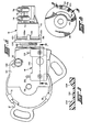
- the switch 18 has a housing 110 with a stationary contact assembly, indicated generally at 112, secured to the housing 110 by suitable fastener, as for example, rivet 114, which retains a terminal 116 which has connected thereto electrical lead 120.
- a second terminal is provided by a fastener, such as rivet 118, which secures terminal 120 to the housing, which terminal has attached thereto the electrical lead 122.
- Rivet 118 also attaches to the housing a snap-acting switchblade mechanism, indicated generally at 122, which has attached thereto movable contact 124 for making and breaking an electrical circuit between-contact 124 and stationary contact assembly 112.
- An actuator member 126 is provided and is pivotally mounted on housing 110, at the right end thereof with respect to Figure 7, by a portion 128 received in an aperture provided in the wall of housing 110.
- the actuator 126 has provided thereon a cam follower 130 shown on the left end thereof in Figure 7, which cam follower is received against a cam surface provided on rotary cam face 38 as will be hereinafter described.
- an arcuate recess 132 is provided about a sector of the outer periphery of the lower face of cam flange 38, the recess 132, having ramps 134 provided at the ends thereof.
- the cam follower 130 of switch actuator 126 is received in the recess 132; and, so long as cam follower 130 is not engaged in either of the cam surfaces 134 or the surface 38, switch 18 is not actuated.
- cover 30 is shown as having an arcuate slot 136 provided therein for receiving the fastener 32 in such a manner as to permit rotation of the cover 30 with respect to body 12 by loosening of fastener 32.
- housing 110 of switch 18 secured to the cover 30, rotation of the cover 30 causes rotary movement of the cam follower 30 with respect to the recess 132 and thereby permits adjustment of the position of cam follower 30 with respect to cam surfaces 134 for an initial or at-rest position of cam surface 38.
- Figure 11 shows the signal output plotted as ordinates as a function of angle of rotation of cam 14 plotted as obscissae. It will be understood by those skilled in the art that the choice of diaphragm area, force constant of the tension spring and configuration angular position of cam surface 42 are suitably chosen to give the desired signal output which may differ, as desired, from the relationship shown in Figure 11.
- the present invention thus provides a fluid pressure signal controller having a regulated fluid pressure output signal which may be selectively varied by a mechanical input as, for example, the position of a rotary shaft connected to an internal combustion engine throttle.
- a switch mechanism is also actuated by movement of a cam rotated by the mechanical input.
- the value of the regulated fluid pressure output signal is controlled by a force-balance type modulator valve having the preload or bias thereon varied during service operation by-movement of the mechanical input.
- the modulator valve is attached to the controller body by a slidable mounting which is easily and conveniently adjusted by rotation of an annular ring threadedly connected to the body.
- the present invention thus provides an easily calibrated and adjusted fluid pressure signal controller having accompanied therewith an electrical switching function.
Landscapes
- Engineering & Computer Science (AREA)
- Physics & Mathematics (AREA)
- Chemical & Material Sciences (AREA)
- Combustion & Propulsion (AREA)
- Mechanical Engineering (AREA)
- General Engineering & Computer Science (AREA)
- Fluid Mechanics (AREA)
- General Physics & Mathematics (AREA)
- Automation & Control Theory (AREA)
- Mechanically-Actuated Valves (AREA)
- Control Of Fluid Pressure (AREA)
- Exhaust-Gas Circulating Devices (AREA)
Applications Claiming Priority (2)
| Application Number | Priority Date | Filing Date | Title |
|---|---|---|---|
| US146903 | 1980-05-05 | ||
| US06/146,903 US4315521A (en) | 1980-05-05 | 1980-05-05 | Fluid pressure signal controller |
Publications (2)
| Publication Number | Publication Date |
|---|---|
| EP0039480A2 true EP0039480A2 (de) | 1981-11-11 |
| EP0039480A3 EP0039480A3 (de) | 1982-02-17 |
Family
ID=22519500
Family Applications (1)
| Application Number | Title | Priority Date | Filing Date |
|---|---|---|---|
| EP19810103254 Withdrawn EP0039480A3 (de) | 1980-05-05 | 1981-04-30 | Fluiddrucksteuervorrichtung |
Country Status (5)
| Country | Link |
|---|---|
| US (1) | US4315521A (de) |
| EP (1) | EP0039480A3 (de) |
| JP (1) | JPS573110A (de) |
| AU (1) | AU6941681A (de) |
| CA (1) | CA1160717A (de) |
Families Citing this family (4)
| Publication number | Priority date | Publication date | Assignee | Title |
|---|---|---|---|---|
| JPS5745618A (en) * | 1980-09-01 | 1982-03-15 | Aisin Seiki Co Ltd | Negative pressure controlling valve |
| JPS57159931A (en) * | 1981-03-27 | 1982-10-02 | Aisin Seiki Co Ltd | Throttle opening response signal generator |
| US4469120A (en) * | 1982-08-30 | 1984-09-04 | Eaton Corporation | Fluid pressure and signal controller |
| JPH09132347A (ja) * | 1995-11-07 | 1997-05-20 | Nec Corp | 紙葉類集積機構 |
Family Cites Families (11)
| Publication number | Priority date | Publication date | Assignee | Title |
|---|---|---|---|---|
| US2550011A (en) * | 1950-03-02 | 1951-04-24 | Refinite Corp | Control valve |
| US3015963A (en) * | 1959-04-20 | 1962-01-09 | A W Cash Valve Mfg Corp | Valve mechanism |
| US3476316A (en) * | 1967-04-12 | 1969-11-04 | Dole Valve Co | Vacuum regulator |
| US3770195A (en) * | 1972-03-24 | 1973-11-06 | Eaton Corp | Temperature control system and vacuum modulator valve therefor |
| US3842814A (en) * | 1972-12-15 | 1974-10-22 | Colt Ind Operating Corp | Exhaust gas recirculation system |
| US3856045A (en) * | 1973-03-08 | 1974-12-24 | Eaton Corp | Vacuum control valve |
| DE2329029C3 (de) * | 1973-06-07 | 1979-04-12 | Robert Bosch Gmbh, 7000 Stuttgart | Steuereinrichtung zum Betrieb einer Brennkraftmaschine |
| US3831841A (en) * | 1974-01-30 | 1974-08-27 | Eaton Corp | Temperature control system and vacuum modulator valve therefor |
| DE2652983C3 (de) * | 1976-11-22 | 1980-04-30 | Pierburg Gmbh & Co Kg, 4040 Neuss | Steuereinrichtung für Brennkraftmaschinen |
| US4245780A (en) * | 1978-04-18 | 1981-01-20 | Eaton Corporation | Temperature regulator assembly and signal modulator therefor |
| US4316479A (en) * | 1979-10-29 | 1982-02-23 | Eaton Corporation | Vacuum modulator valve and subassembly therefor |
-
1980
- 1980-04-10 AU AU69416/81A patent/AU6941681A/en not_active Abandoned
- 1980-05-05 US US06/146,903 patent/US4315521A/en not_active Expired - Lifetime
-
1981
- 1981-04-30 JP JP6431381A patent/JPS573110A/ja active Pending
- 1981-04-30 EP EP19810103254 patent/EP0039480A3/de not_active Withdrawn
- 1981-05-04 CA CA000376782A patent/CA1160717A/en not_active Expired
Also Published As
| Publication number | Publication date |
|---|---|
| AU6941681A (en) | 1981-11-12 |
| EP0039480A3 (de) | 1982-02-17 |
| JPS573110A (en) | 1982-01-08 |
| US4315521A (en) | 1982-02-16 |
| CA1160717A (en) | 1984-01-17 |
Similar Documents
| Publication | Publication Date | Title |
|---|---|---|
| US4944269A (en) | Accelerating pedal for electronic throttle actuation system | |
| EP0220570B1 (de) | Erregerspulenbetätigter Druckregler für Fluide | |
| US4784008A (en) | Analogue manipulator with preferential orientations | |
| US6910496B2 (en) | Gas conversion assembly | |
| KR920006479B1 (ko) | 개스압력/개스유량 보상직접작동식 압력조절장치 | |
| USRE34302E (en) | Accelerating pedal for electronic throttle actuation system | |
| AU609259B2 (en) | Droop compensated direct acting pressure regulator | |
| US4315521A (en) | Fluid pressure signal controller | |
| EP0036792B1 (de) | Druckabhängige Regelvorrichtung | |
| US4172412A (en) | Fluid operated diaphragm assembly having a pair of like opposed diaphragms | |
| US4411154A (en) | Switch for sensing a preset position of a throttle valve | |
| EP0398858A2 (de) | An erhöhten Druck angepasster, droop-kompensierter direktwirkender Druckregler | |
| JPS6325172B2 (de) | ||
| US4464551A (en) | Electric circuit controlling device and method of operating same | |
| US4409941A (en) | Control system for internal combustion engines | |
| US3307785A (en) | On-off and modulating condition control valve | |
| EP0565028B1 (de) | Druckschalter | |
| US4493957A (en) | Multimodal pressure switch | |
| US4540153A (en) | Temperature sensitive negative-pressure control valve | |
| US4322032A (en) | Thermally responsive valve device | |
| US3246094A (en) | Delayed return pressure actuated device | |
| US4458116A (en) | Throttle operated controller assembly | |
| WO1995006904A1 (en) | Engine fuel flow control mechanism | |
| JPH06283081A (ja) | 圧力応答電気スイッチ | |
| US4090286A (en) | Fluid operated diaphragm assembly and method of making the same |
Legal Events
| Date | Code | Title | Description |
|---|---|---|---|
| PUAI | Public reference made under article 153(3) epc to a published international application that has entered the european phase |
Free format text: ORIGINAL CODE: 0009012 |
|
| AK | Designated contracting states |
Designated state(s): DE FR GB IT SE |
|
| 17P | Request for examination filed |
Effective date: 19810928 |
|
| PUAL | Search report despatched |
Free format text: ORIGINAL CODE: 0009013 |
|
| RHK1 | Main classification (correction) |
Ipc: G05D 16/06 |
|
| AK | Designated contracting states |
Designated state(s): DE FR GB IT SE |
|
| STAA | Information on the status of an ep patent application or granted ep patent |
Free format text: STATUS: THE APPLICATION IS DEEMED TO BE WITHDRAWN |
|
| 18D | Application deemed to be withdrawn |
Effective date: 19831102 |
|
| RIN1 | Information on inventor provided before grant (corrected) |
Inventor name: KENNY, ANDREW AUGUSTINE Inventor name: ANDERSON, PATRICK JANES |