EP0039293B1 - Dispositif pour la mesure très précise des pressions de fluide avec affichage de la pression mesurée - Google Patents
Dispositif pour la mesure très précise des pressions de fluide avec affichage de la pression mesurée Download PDFInfo
- Publication number
- EP0039293B1 EP0039293B1 EP81400669A EP81400669A EP0039293B1 EP 0039293 B1 EP0039293 B1 EP 0039293B1 EP 81400669 A EP81400669 A EP 81400669A EP 81400669 A EP81400669 A EP 81400669A EP 0039293 B1 EP0039293 B1 EP 0039293B1
- Authority
- EP
- European Patent Office
- Prior art keywords
- piston
- pressure
- cylinder
- balance
- shaft
- Prior art date
- Legal status (The legal status is an assumption and is not a legal conclusion. Google has not performed a legal analysis and makes no representation as to the accuracy of the status listed.)
- Expired
Links
- 238000005259 measurement Methods 0.000 title claims description 24
- 239000012530 fluid Substances 0.000 title claims description 10
- 230000005540 biological transmission Effects 0.000 claims description 7
- 230000001133 acceleration Effects 0.000 claims description 3
- 230000000694 effects Effects 0.000 claims description 3
- 230000010354 integration Effects 0.000 claims description 3
- 239000006096 absorbing agent Substances 0.000 claims 2
- 239000000314 lubricant Substances 0.000 claims 2
- 230000001050 lubricating effect Effects 0.000 claims 1
- 239000003921 oil Substances 0.000 description 13
- 230000005484 gravity Effects 0.000 description 7
- 239000007789 gas Substances 0.000 description 5
- 229910001220 stainless steel Inorganic materials 0.000 description 5
- 239000010935 stainless steel Substances 0.000 description 5
- 230000000712 assembly Effects 0.000 description 3
- 238000000429 assembly Methods 0.000 description 3
- 238000006243 chemical reaction Methods 0.000 description 3
- 238000005461 lubrication Methods 0.000 description 3
- 230000008901 benefit Effects 0.000 description 2
- 239000010687 lubricating oil Substances 0.000 description 2
- 230000009466 transformation Effects 0.000 description 2
- 238000000844 transformation Methods 0.000 description 2
- 238000005303 weighing Methods 0.000 description 2
- 101100536354 Drosophila melanogaster tant gene Proteins 0.000 description 1
- VVQNEPGJFQJSBK-UHFFFAOYSA-N Methyl methacrylate Chemical compound COC(=O)C(C)=C VVQNEPGJFQJSBK-UHFFFAOYSA-N 0.000 description 1
- 240000008042 Zea mays Species 0.000 description 1
- 230000000903 blocking effect Effects 0.000 description 1
- 230000008859 change Effects 0.000 description 1
- 238000004140 cleaning Methods 0.000 description 1
- 238000004891 communication Methods 0.000 description 1
- 230000008878 coupling Effects 0.000 description 1
- 238000010168 coupling process Methods 0.000 description 1
- 238000005859 coupling reaction Methods 0.000 description 1
- 238000013016 damping Methods 0.000 description 1
- 229920001971 elastomer Polymers 0.000 description 1
- 239000000806 elastomer Substances 0.000 description 1
- 238000001914 filtration Methods 0.000 description 1
- 239000011521 glass Substances 0.000 description 1
- 238000009434 installation Methods 0.000 description 1
- 238000004519 manufacturing process Methods 0.000 description 1
- 238000000034 method Methods 0.000 description 1
- 238000012986 modification Methods 0.000 description 1
- 230000004048 modification Effects 0.000 description 1
- 230000003071 parasitic effect Effects 0.000 description 1
- 238000012545 processing Methods 0.000 description 1
- 230000035945 sensitivity Effects 0.000 description 1
- 238000012546 transfer Methods 0.000 description 1
- UONOETXJSWQNOL-UHFFFAOYSA-N tungsten carbide Chemical compound [W+]#[C-] UONOETXJSWQNOL-UHFFFAOYSA-N 0.000 description 1
- 239000010913 used oil Substances 0.000 description 1
Images


Classifications
-
- G—PHYSICS
- G01—MEASURING; TESTING
- G01L—MEASURING FORCE, STRESS, TORQUE, WORK, MECHANICAL POWER, MECHANICAL EFFICIENCY, OR FLUID PRESSURE
- G01L27/00—Testing or calibrating of apparatus for measuring fluid pressure
- G01L27/002—Calibrating, i.e. establishing true relation between transducer output value and value to be measured, zeroing, linearising or span error determination
- G01L27/005—Apparatus for calibrating pressure sensors
Definitions
- the subject of the invention is a device for very precise measurement of a fluid pressure, as defined in the preamble of claim 1. It finds in particular an application in the measurement of the pressures of the fluid, in particular of gases and fluids hydraulic, with very high precision, in particular for producing pressure standards suitable for verifying and calibrating pressure gauges, as well as pressure sensors and transmitters.
- Pressure standards are known, marketed by the applicant, which essentially comprise a cylinder with a high precision vertical axis in which slides a piston whose upper part carries a horizontal plate, means being provided for driving the piston in rotation in the cylinder. in order to center it properly in this one.
- the pressure to be measured which acts on the underside of the piston, is balanced by calibrated masses placed on the plate.
- M the total mass acting on the piston from top to bottom
- S the effective section of the cylinder-piston assembly on which acts, from bottom to top, the pressure P to be measured and g the acceleration of gravity
- Such pressure standards are very precise, but they require the use of a series of calibrated masses of high precision, made for example of stainless steel, at a high price, as well as means of automatic installation and removal. masses on the set.
- the handling of the masses takes a certain time, because the system must be balanced by means of a certain number of masses, and the indications given on the masses must then be read and summed up in order to obtain M.
- the pressure P is then determined by the above formula (1).
- the masses also carry an indication of pressure corresponding to a well-defined effective cross-section S.
- the present invention aims to facilitate and accelerate the measurement of the pressure by allowing an instantaneous display, preferably in digital (or digital) form, of the mass M and therefore of the pressure P.
- the invention makes it possible, instead of balancing the pressure by a total mass constituted by a series of elementary calibrated masses (as in the prior art), to “weigh this pressure, that is to say to make the pressure act on a scale which measures the force corresponding to this pressure (we know that a pressure is equal to a force divided by the surface on which this force is applied).
- this “weighing” is carried out by means of a high precision balance with immediate display, in particular an electromagnetic rebalancing balance, hereinafter simply called electromagnetic balance. It is a dynamometric balance.
- the subject of the invention is therefore a device for very precise measurement of the fluid pressures, as characterized in the characterizing part of claim 1.
- the speed of rotation of the piston corresponds to a duration of complete rotation of the latter in the cylinder which is less than the integration time of the electronic device for measuring the balance in order to have a stable display determined by the average of the forces applied. to the piston during its rotation following a full revolution.
- means are provided for limiting the torque of the motor driving the piston in rotation in the event of the piston blocking in the cylinder, under the effect of an overpressure for example.
- the measurement unit essentially comprising the cylinder and the piston, is interchangeable, which makes it possible to use, with the same balance, different measurement elements comprising effective sections, to which the pressure to be measured, of different dimensions, which makes it possible to measure, with excellent precision, pressures in very different ranges of values.
- the effective sections of the measuring elements are chosen so that, under normal conditions of pressure and temperature and for the normal value of g, a whole and simple number of bars (or pounds per square inch) is balanced by a mass of 1 kg.
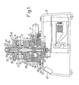
- a device comprises three assemblies, namely an assembly A essentially comprising the measurement unit with the cylinder 1 and the piston 2, a balance electromagnetic B with a shaft 3 intended to receive the force to be measured and a connection assembly C transmitting the force of the piston 2 of the assembly A to the shaft 3 of the blance B.
- Figure 1 represents all the elements A , B and C
- Figure 2 illustrates, but on a larger scale, only the sets A and C which are separated, on this figurine, by the line XX in broken lines.
- the assembly A (see more particularly FIG. 2) firstly comprises, as indicated above, a cylinder 1 and a piston 2 which together constitute the unit of measurement proper. Cylinder 1 is vertical.
- the cylinder 1 is mounted in a measuring block 1b which has a bottom or cylinder head 1a at its upper part.
- the piston 2 can slide vertically in the cylinder 1 in which it moves with viscous friction, a film of hydraulic fluid being interposed between the two.
- the piston 2 is rotated in the cylinder 1 by means of an electric motor 4 rotating a pulley 5 which carries, in a groove 6, an O-ring 7 (made of an elastomer) rubbing on the periphery of a pulley 8 which rotates, in turn, the head 9 of the piston 2 secured in rotation to the pulley 8 by a pin 10 carrying a bearing 11.
- a friction drive is carried out which limits the torque of the motor 4 in the event of piston 2 jamming under the effect of an overpressure acting on the pistori 2 from top to bottom.
- the pressure to be measured is applied to the chamber 12 existing between the bottom 1a of the cylinder 1 and the upper end of the piston 2.
- an amount of oil 13 is provided in the lower part of an annular chamber 14 which surrounds the measuring block 1b and which communicates with the chamber 12 by radial channels 15 and 17.
- the level 18 of oil in the chamber 14 can be easily identified by means of an envelope 16 made of an unbreakable organic glass, for example of methyl methacrylate. This oil level also prevails inside the chamber 12 thanks to the radial channels 17.
- the level 18 of the oil in the chamber 14 must therefore be maintained between the channels 15 and the channels 17. It is on the 'mouth 19, which communicates via channels 20, 21 and a frustoconical recess 22 with the chamber 14, and therefore finally with the chamber 12, that the pressure to be measured is applied.
- the chambers 12 and 14 When it comes to measuring an oil pressure (or other hydraulic fluid), the chambers 12 and 14 are filled with oil through the frustoconical recess 22 and the channels 21 and 20, applying the oil pressure at mouth 19; through channels 23 and 24, the chambers 12 and 14 are purged through the opening 25 of the gas they contain. At the end of the operation, the oil is drained through the channels 26 and 27 and the discharge opening 28.
- the measuring element 1, 2 can be changed by acting on the screws 34 and the nut 35.
- the nut 36 makes it possible to change the mouthpiece 19 constituting a connector and the cleaning of the annular chamber 14.
- the assembly C is used to transmit this force to the shaft 3 of the balance which allows its measurement.
- the purpose of this assembly C is to transmit this force while limiting it in the event of an overpressure acting on the piston 2.
- the force transmission member of the assembly C is constituted by a connecting rod 37.
- a ball bearing 38 is provided with a bearing 39 at the upper part of the connecting rod 37 in the lower head of the piston 2, so as to be able to center them perfectly relative to the axis of the piston 2 and to the axis of the connecting rod 37 by means of the ball 38.
- the limitation and damping of the force applied by the piston 2 on the shaft 3 of the balance, in order to protect it, are achieved by means of a double damper 40,41 and a load limiter 42, the whole being housed in a part 43 whose frustoconical upper part is disposed in a cooperating part 44 of the assembly A and on which the piston head 9 abuts in the event of overload.
- the used lubricating oil is discharged through a channel 46 arranged in room 44.
- the assembly A can be separated from the assembly B constituting the actual balance (FIG. 1) using the screws 45.
- the assembly B this will not be described in detail since it is constituted by a precision electromagnetic balance of conventional type.
- scales include precision electronic scales from the Swiss company METTLER, of the PL series, electronic scales from the German company SARIORIUS, scales from the German companies KERN and SAUTER.
- Such scales display directly, preferably in digital (or digital) form, on a dial 47, the force due to the masses applied to their axis 3.
- FIGS. 1 and 3 we have illustrated schematically inside the balance essentially to show that it includes means for electromagnetic rebalancing of the force applied to the axis 3.
- the actual measuring element constituted by the cylinder 1 and the piston 2 is interchangeable, so as to be able to implement in the same device different effective sections, which makes it possible to measure, while remaining in the precision range of the balance, very different values of pressure.
- the theoretical effective sections of the interchangeable measuring elements are such that, under normal conditions of terrestrial gravity (9.806 65 m / s 2 ), of atmospheric pressure (1.013 25 bar) and at the temperature of 20 ° C, by loading the piston with a stainless steel mass of 1 kg, a whole and simple number of bars (or psi) is balanced.
- KN This integer is specific to each measurement element and is called the normal conversion coefficient (KN).
- g n being the acceleration of normal gravity
- S th the effective theoretical average section of the two sections of the cylinder and the piston (for the different positions of the piston which turns in the cylinder)
- Pair and Pinox the densities or the densities of air and stainless steel respectively.
- the local terrestrial gravity (g l ) at the place of use of the measuring element is, in general, different from the normal gravity (g n ); it follows that, for a temperature of 20 ° C, the general expression of the pressure measured by an element loaded with a mass of stainless steel M is:
- the auto-calibration procedure of the instrument is as follows: gravity instead of calibration being g , a mass M corresponding to the maximum range is placed on the balance and the gain of the balance is adjusted so that the digital display of the scale indicates the value
- this auto-calibration remains valid even if the instrument, once adjusted, is used in a place where the local gravity is different from that of the calibration place.
- the coupling produced according to the invention between a measuring element, constituted by a cylinder 1 and a piston 7, and an electromagnetic balance, the gain of which has been adjusted as indicated above, makes it possible to produce a device of which it is possible at any moment check the calibration using masses 48 placed to act on the connecting rod 37 and therefore on the shaft 3 of the balance, and this without having to call on an external pressure calibration. It is therefore a self-calibrating device (since there is no need for an external pressure standard).
- the rotation of the piston 2 in the cylinder 1 allows good sensitivity and good repeatability of the measurements, since it ensures the centering of the piston by the creation of a uniform oil film in the clearance between the piston and the cylinder.
- This rotation of the piston implies the connection between the piston 2 and the shaft 3 of the balance, but it was indicated above how the connection assembly C makes it possible to achieve such a connection with transmission of force, but with limitation in the event of overpressure and filtration of parasitic effects due to rotation of the piston.
- the speed of rotation of the piston 1 in the cylinder 2 is advantageously chosen so that the piston performs a complete rotation for a duration which is less than the duration of integration, that is to say the measurement rate, of the electronic device. of the balance, which makes it possible to have a stable display at 47 by eliminating the fluctuations in the measurement due to the rotation of the piston.
- the measurement rate of the balance is between 0.2 and 1 second and in this case the speed of rotation of the piston must be greater than 5 to 1 revolutions per second.
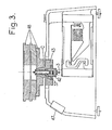
- FIG. 4 the assemblies A and C have been illustrated according to a second embodiment of the invention, using the same reference numbers as in FIGS. 1 to 3 to designate the corresponding elements.
- the annular part 51 weighs for example 1 kg and it is intended to create an offset or original bias in the display of the pressure on the rocker.
- the pressure to be measured always acts on the mouth 19 and therefore on the upper face of the piston 2 in the chamber 12 in communication with the mouth 19.
- the balance When it is the atmospheric pressure which acts on the mouth 19, the balance displays a numerical value greater than 10,000 points due to the part 51.
- This numerical value is brought to zero by acting on the means for adjusting the electromagnetic balance.
- a double lubrication system is provided with two reservoirs 52 and 14 for the lubricating oil.
- the pressure is transmitted from the piston 2 to the scale by a ball 59 (for example made of tungsten carbide) centered by a bearing 60, and a rod 61 acting on the upper part of the scale B ( Figures 1 and 3 ) by means of a damper constituted by an O-ring 62.
- a ball 59 for example made of tungsten carbide
- a bearing 60 centered by a bearing 60
- a rod 61 acting on the upper part of the scale B ( Figures 1 and 3 ) by means of a damper constituted by an O-ring 62.
- the device according to the invention ultimately has the advantage, over the devices of the prior art, of avoiding the use of a series of calibrated masses of stainless steel, which are expensive and whose handling is long and often painful. ; the device according to the invention also avoids the use of means for automatically placing and removing calibrated masses, means which are bulky and which are expensive; in addition, an automatic display, in particular digital (or digital), is obtained, which further increases the convenience of use and allows the transfer of information to data acquisition and processing systems.
Landscapes
- Chemical & Material Sciences (AREA)
- Analytical Chemistry (AREA)
- Physics & Mathematics (AREA)
- General Physics & Mathematics (AREA)
- Measuring Fluid Pressure (AREA)
Applications Claiming Priority (2)
| Application Number | Priority Date | Filing Date | Title |
|---|---|---|---|
| FR8009889A FR2481801A1 (fr) | 1980-04-30 | 1980-04-30 | Dispositif pour la mesure tres precise des pressions de fluide avec affichage de la pression mesuree |
| FR8009889 | 1980-04-30 |
Publications (2)
| Publication Number | Publication Date |
|---|---|
| EP0039293A1 EP0039293A1 (fr) | 1981-11-04 |
| EP0039293B1 true EP0039293B1 (fr) | 1985-04-03 |
Family
ID=9241575
Family Applications (1)
| Application Number | Title | Priority Date | Filing Date |
|---|---|---|---|
| EP81400669A Expired EP0039293B1 (fr) | 1980-04-30 | 1981-04-28 | Dispositif pour la mesure très précise des pressions de fluide avec affichage de la pression mesurée |
Country Status (4)
| Country | Link |
|---|---|
| US (1) | US4413526A (enExample) |
| EP (1) | EP0039293B1 (enExample) |
| DE (1) | DE3169644D1 (enExample) |
| FR (1) | FR2481801A1 (enExample) |
Families Citing this family (9)
| Publication number | Priority date | Publication date | Assignee | Title |
|---|---|---|---|---|
| US4491016A (en) * | 1981-11-05 | 1985-01-01 | Pfister Gmbh | Method and apparatus for measuring the pressure of a fluid |
| CA1201608A (en) * | 1982-11-22 | 1986-03-11 | Yoshiteru Sonoda | Precision pressure gauge |
| FR2580807B1 (fr) * | 1985-04-22 | 1987-12-24 | Pierre Delajoud | Perfectionnements aux dispositifs pour la mesure tres precise des pressions de fluide |
| GB8616157D0 (en) * | 1986-07-02 | 1986-08-06 | Furness Controls Ltd | Calibrated gas pressure |
| JPH0545941Y2 (enExample) * | 1986-09-30 | 1993-11-30 | ||
| US5142483A (en) * | 1990-04-24 | 1992-08-25 | Caltechnix Corporation | Pressure regulating system for positive shut-off pressure controller |
| US5452613A (en) * | 1993-10-04 | 1995-09-26 | Granville-Phillips Company | Wide range vacuum gauge |
| CN106017793B (zh) * | 2016-07-29 | 2019-08-02 | 昆山市创新科技检测仪器有限公司 | 一种用于力标准机的精度检测装置、力值比对机以及力标准机精度检测方法 |
| CN110118629B (zh) * | 2019-05-31 | 2024-10-29 | 辽宁红沿河核电有限公司 | 一种核电站大气压力测量装置 |
Family Cites Families (3)
| Publication number | Priority date | Publication date | Assignee | Title |
|---|---|---|---|---|
| GB1117198A (en) * | 1965-06-15 | 1968-06-19 | Kobe Steel Ltd | A system and apparatus for producing and maintaining a reference pressure in a vessel |
| US3744316A (en) * | 1971-08-26 | 1973-07-10 | Honeywell Inc | Ultra-low fluid pressure and ultra-low force measuring apparatus |
| CH635196A5 (en) * | 1978-11-14 | 1983-03-15 | Peter Huber | Device having a pressure-measuring instrument and calibration means for calibrating the same, and method for operating the device |
-
1980
- 1980-04-30 FR FR8009889A patent/FR2481801A1/fr active Granted
-
1981
- 1981-04-27 US US06/257,610 patent/US4413526A/en not_active Expired - Lifetime
- 1981-04-28 EP EP81400669A patent/EP0039293B1/fr not_active Expired
- 1981-04-28 DE DE8181400669T patent/DE3169644D1/de not_active Expired
Also Published As
| Publication number | Publication date |
|---|---|
| FR2481801B1 (enExample) | 1983-02-18 |
| DE3169644D1 (en) | 1985-05-09 |
| EP0039293A1 (fr) | 1981-11-04 |
| US4413526A (en) | 1983-11-08 |
| FR2481801A1 (fr) | 1981-11-06 |
Similar Documents
| Publication | Publication Date | Title |
|---|---|---|
| EP0039293B1 (fr) | Dispositif pour la mesure très précise des pressions de fluide avec affichage de la pression mesurée | |
| FR2580401A1 (fr) | Appareil et procede pour mesurer les proprietes visco-elastiques de materiaux | |
| EP0325521A1 (fr) | Dispositif d'équilibrage automatique d'une centrifugeuse en fonctionnement | |
| FR2644888A1 (fr) | Dispositif de mesure pour la saisie de la charge de palier appliquee sur un palier de cylindre | |
| EP2128723A1 (fr) | Procédé de fabrication ou d'assemblage d'un oscillateur et oscillateur obtenu selon ce procédé | |
| FR2799837A1 (fr) | Procede et dispositif de mesure d'efforts en presence d'une pression exterieure | |
| WO2005059492A2 (fr) | Dispositif de mesure de charge sur un palier, palier à roulement à dispositif de mesure de charge et machine à tambour rotatif. | |
| WO1991015763A1 (fr) | Dispositif et procede pour ameliorer l'evaluation des performances d'un lubrifiant | |
| FR2580402A1 (fr) | Permeametre | |
| EP0202970B1 (fr) | Dispositif à piston pour la mesure très précise des pressions de fluide | |
| FR2577042A1 (fr) | Dispositif de correction automatique pour un systeme de pesee de combinaison | |
| CA2734993A1 (fr) | Procede permettant d'analyser le debit d'injection coup par coup fourni par un systeme d'injection de carburant utilise dans un moteur thermique de forte puissance | |
| EP0244324B1 (fr) | Capteur de force à jauges résistives | |
| CH642745A5 (fr) | Dispositif differentiel de pesage. | |
| EP4016199A1 (fr) | Dispositif et procede de test d'une propriete mecanique d'un arbre horloger | |
| EP0028568B1 (fr) | Jauge d'étalonnage | |
| EP0389727B1 (fr) | Installation de mesure des déformations d'un objet soumis à des contraintes | |
| FR2773611A1 (fr) | Appareil pour mesurer la pression differentielle entre au moins deux fluides | |
| FR2677449A1 (fr) | Procede et dispositif d'etalonnage de couplemetres et couplemetre compact adapte au dispositif. | |
| EP0513882B1 (fr) | Système volumétrique mesureur de débit de fluide | |
| EP0151057A2 (fr) | Interféromètre de vitesse à sensibilité continûment variable | |
| FR2754342A1 (fr) | Cellule de conversion d'une pression differentielle en signal electrique | |
| EP0119117A1 (fr) | Dispositifs électro-optiques de détection et de mesure de déformations | |
| EP4316987B1 (fr) | Procede de determination de la position d'un dispositif d'actionnement, dispositif d'actionnement correspondant | |
| WO2010026319A1 (fr) | Procede et dispositif de mesure de balourd de vilebrequin |
Legal Events
| Date | Code | Title | Description |
|---|---|---|---|
| PUAI | Public reference made under article 153(3) epc to a published international application that has entered the european phase |
Free format text: ORIGINAL CODE: 0009012 |
|
| AK | Designated contracting states |
Designated state(s): DE FR GB |
|
| 17P | Request for examination filed |
Effective date: 19820424 |
|
| GRAA | (expected) grant |
Free format text: ORIGINAL CODE: 0009210 |
|
| AK | Designated contracting states |
Designated state(s): DE FR GB |
|
| REF | Corresponds to: |
Ref document number: 3169644 Country of ref document: DE Date of ref document: 19850509 |
|
| PLBE | No opposition filed within time limit |
Free format text: ORIGINAL CODE: 0009261 |
|
| STAA | Information on the status of an ep patent application or granted ep patent |
Free format text: STATUS: NO OPPOSITION FILED WITHIN TIME LIMIT |
|
| 26N | No opposition filed | ||
| PGFP | Annual fee paid to national office [announced via postgrant information from national office to epo] |
Ref country code: DE Payment date: 20000330 Year of fee payment: 20 |
|
| PGFP | Annual fee paid to national office [announced via postgrant information from national office to epo] |
Ref country code: GB Payment date: 20000331 Year of fee payment: 20 |
|
| PGFP | Annual fee paid to national office [announced via postgrant information from national office to epo] |
Ref country code: FR Payment date: 20000427 Year of fee payment: 20 |
|
| PG25 | Lapsed in a contracting state [announced via postgrant information from national office to epo] |
Ref country code: GB Free format text: LAPSE BECAUSE OF EXPIRATION OF PROTECTION Effective date: 20010427 |
|
| REG | Reference to a national code |
Ref country code: GB Ref legal event code: PE20 Effective date: 20010427 |