EP0039200A2 - Radialpressmaschine - Google Patents
Radialpressmaschine Download PDFInfo
- Publication number
- EP0039200A2 EP0039200A2 EP81301780A EP81301780A EP0039200A2 EP 0039200 A2 EP0039200 A2 EP 0039200A2 EP 81301780 A EP81301780 A EP 81301780A EP 81301780 A EP81301780 A EP 81301780A EP 0039200 A2 EP0039200 A2 EP 0039200A2
- Authority
- EP
- European Patent Office
- Prior art keywords
- die
- segments
- segment
- set forth
- block
- Prior art date
- Legal status (The legal status is an assumption and is not a legal conclusion. Google has not performed a legal analysis and makes no representation as to the accuracy of the status listed.)
- Granted
Links
- 238000002788 crimping Methods 0.000 title claims abstract description 48
- 230000000712 assembly Effects 0.000 description 8
- 238000000429 assembly Methods 0.000 description 8
- 230000005484 gravity Effects 0.000 description 6
- 230000009471 action Effects 0.000 description 5
- 239000012530 fluid Substances 0.000 description 3
- 230000000717 retained effect Effects 0.000 description 3
- 230000008901 benefit Effects 0.000 description 2
- 230000008602 contraction Effects 0.000 description 2
- 239000013536 elastomeric material Substances 0.000 description 2
- 238000007373 indentation Methods 0.000 description 2
- 239000002184 metal Substances 0.000 description 2
- 239000011435 rock Substances 0.000 description 2
- 125000006850 spacer group Chemical group 0.000 description 2
- 230000004075 alteration Effects 0.000 description 1
- 230000000295 complement effect Effects 0.000 description 1
- 230000006835 compression Effects 0.000 description 1
- 238000007906 compression Methods 0.000 description 1
- 238000010276 construction Methods 0.000 description 1
- 230000001419 dependent effect Effects 0.000 description 1
- 230000000694 effects Effects 0.000 description 1
- 230000007257 malfunction Effects 0.000 description 1
- 230000007246 mechanism Effects 0.000 description 1
- 238000002360 preparation method Methods 0.000 description 1
- 230000003252 repetitive effect Effects 0.000 description 1
- 230000000284 resting effect Effects 0.000 description 1
- 230000007480 spreading Effects 0.000 description 1
- 230000000007 visual effect Effects 0.000 description 1
Images

Classifications
-
- B—PERFORMING OPERATIONS; TRANSPORTING
- B25—HAND TOOLS; PORTABLE POWER-DRIVEN TOOLS; MANIPULATORS
- B25B—TOOLS OR BENCH DEVICES NOT OTHERWISE PROVIDED FOR, FOR FASTENING, CONNECTING, DISENGAGING OR HOLDING
- B25B27/00—Hand tools, specially adapted for fitting together or separating parts or objects whether or not involving some deformation, not otherwise provided for
- B25B27/02—Hand tools, specially adapted for fitting together or separating parts or objects whether or not involving some deformation, not otherwise provided for for connecting objects by press fit or detaching same
- B25B27/10—Hand tools, specially adapted for fitting together or separating parts or objects whether or not involving some deformation, not otherwise provided for for connecting objects by press fit or detaching same inserting fittings into hoses
-
- B—PERFORMING OPERATIONS; TRANSPORTING
- B21—MECHANICAL METAL-WORKING WITHOUT ESSENTIALLY REMOVING MATERIAL; PUNCHING METAL
- B21D—WORKING OR PROCESSING OF SHEET METAL OR METAL TUBES, RODS OR PROFILES WITHOUT ESSENTIALLY REMOVING MATERIAL; PUNCHING METAL
- B21D39/00—Application of procedures in order to connect objects or parts, e.g. coating with sheet metal otherwise than by plating; Tube expanders
- B21D39/04—Application of procedures in order to connect objects or parts, e.g. coating with sheet metal otherwise than by plating; Tube expanders of tubes with tubes; of tubes with rods
- B21D39/046—Connecting tubes to tube-like fittings
-
- Y—GENERAL TAGGING OF NEW TECHNOLOGICAL DEVELOPMENTS; GENERAL TAGGING OF CROSS-SECTIONAL TECHNOLOGIES SPANNING OVER SEVERAL SECTIONS OF THE IPC; TECHNICAL SUBJECTS COVERED BY FORMER USPC CROSS-REFERENCE ART COLLECTIONS [XRACs] AND DIGESTS
- Y10—TECHNICAL SUBJECTS COVERED BY FORMER USPC
- Y10T—TECHNICAL SUBJECTS COVERED BY FORMER US CLASSIFICATION
- Y10T29/00—Metal working
- Y10T29/53—Means to assemble or disassemble
- Y10T29/5367—Coupling to conduit
Definitions
- This invention relates to a machine for crimping the socket of a fitting onto a hose end by the radial contraction of a segmented die assembly and more particularly to improvements in the segmented dies and assembly whereby use of the machine is facilitated.
- This machine is particularly suited for makeup of flexible hose assemblies of various sizes at a field location.
- the machine be designed to reduce the possibility of errors or malfunctions in the hose assembly due to the selection of improper components for a particular size or due to errors in the operation of the machine.
- the machine be versatile so as to accommodate not only the straight end fitting which may not require more than a partial operating cycle of the machine but also that of the bent hose end fitting which may require the full operating cycle and partial disassembly of the machine in order to place the components in position to perform the crimping action.
- Field crimping devices are well established in the prior art for rapidly, economically and consistently making quality hose assemblies. They are capable of achieving high hose assembly standards comparable to factory constructed assemblies. Their ready availability, however, necessitates design and operating characteristics which provide minimal chance for error in makeup of hose assemblies.
- a hydraulic cylinder situated generally over the crimping stage produces a linearly directed force upon a radially contractible die assembly which is received in the tapered bore of a base plate or other reaction body member opposing the force of the cylinder.
- Linear movement of the die assembly into the tapered bore causes a camming or wedging action upon individual segments collectively forming the die assembly, to cause movement of the segments in a radially inward direction such that an inner cylindrical surface thereof receiving the socket of the hose fitting is reduced in diameter, thereby effecting the crimping action.
- the machinery exemplified in the above-identified patents is characterized in particular in that the preferred collet assembly consists of a pair of collet segment halves which may be placed in position in the tapered bore with the inner cylindrical surface thereof in engagement with the collar of the hose fitting.
- the hose and fitting may be raised or shifted somewhat by the operator to settle the die segment halves into a matching configuration in the machine with.the segment halves then being retained therein primarily by the force of gravity but also assisted to some extent by the weight of a spacer plate which is positioned thereover.
- the spacer plate is designed primarily to spread the force of the hydraulic ram and assure even movement of both halves of the die collet but serves as well as to limit the linear movement of the hydraulic ram and thus the radial contraction of the individual collet segments.
- the preferred form of die collet arrangement of these prior art devices is shown in detail in U. S. Patent No. 3,750.452 wherein it is seen that elastomeric material is disposed between adjacent die segments in a split collet arrangment. The elastomeric material retains each of the die segments in each half of the collet and provides a spacing of the collet halves once they are placed in the tapered bore, preparatory to the crimping operation.
- the half collet arrangement is particularly advantageous in providing ease of loading and preparation of the machine and a facility for clearance of obstructions, as for example, those encountered when crimping bent hose ends.
- Bent hose ends are accommodated as well in this form of structure, being limited primarily by the size of the throat. of the die segment support member to which diameter the die segments can be retracted. In fact, in this machine the die segments can be fully removed from the support member. Final crimp diameter is determined by a visual gage device which must be judged by the operator to manually terminate the application of hydraulic force to the actuating ram.
- a crimper assembly for crimping the socket of a hose fitting onto a hose end within a die block having a tapered bore therein, comprising a plurality of die segments for crimping the socket of a hose fitting, said die segments having an outer surface confirming to the bore of said die block and an inner surface for crimping said hose fitting, means connecting adjacent die segments for limited relative movement to facilitate placement and removal of said die segments from said die block, said die segments being positioned in said die block in a circular array to encircle the socket of a hose fitting positioned therein, a die separator supporting said die segments in said die block on a first position therein for receipt of said hose fitting, said die separator engaging each of said die segments to position them in a symmetrical and spaced circular array, and means for urging said die segments simultaneously into said die block with said outer surface in engagement with said tapered bore.
- a crimping machine for radially deforming the socket of a fitting onto the end of a hose, comprising a support member having a tapered cavity therein, a generally circular die segment assembly in said cavity for engaging the socket of a fitting positioned therein and for radially inwardly deforming said socket and means for moving said die segment assembly axially relative to said support member thereby to force said die segment assembly radially inwardly, said die segment assembly comprising a plurality of generally pie- shaped die segments, each die segment having a pair of radial walls, an outer wall having a generally conical curvature conforming to the shape of the tapered cavity in said support member, said outer wall meeting said radial walls, an inner wall having a generally axially-extending cylindrical curvature adapted to conform generally to the outer surface of the socket of a fitting, said inner surface joining said radial walls, and means for supporting said die segment assembly in said cavity in a circumferentially equally-spaced configuration
- said die segment assembly comprising a pluralit
- the preferred forms of the apparatus of the invention are advantageous in several respects over prior art devices in that the individual die segments are linked to one another except at one location to provide a flexible chain. Further, the die segments are supported in an advantageous manner in a tapered die cavity to facilitate operation of the machine.
- the crimping machine comprises a bottom-loading type machine consisting of a rockably mounted overhead hydraulic cylinder which provides a downwardly directed force to drive the die segment assembly into a tapered cavity in a base plate to achieve the radially inwardly directed crimping action.
- the hydraulic cylinder is rockable to provide clearance over the tapered cavity for loading and unloading purposes and is automatically guided through a rocking motion by the cooperation of cam rollers carried by the pusher with a fixed cam plate.
- the cam arrangement is designed to provide a linear motion of the pusher during one portion of its stroke and the rocking motion when the piston rod reaches the position of near full retraction. In this manner, only a short outer portion of the stroke need be utilized when repetitive crimps of straight end fittings are desired and the hose assemblies can be inserted and removed by merely retracting the die segments. When, however, bent end fittings are to be made or the die segment assembly is to be changed, then the pusher can be fully retracted and swung away from the work area to provide suitable clearance.
- the chain of die segments in a unitary assembly assures that the proper combination of die segments will be utilized. Further, the chain of segments may be wrapped around the socket of a fitting in a serial manner, avoiding the requirement that such assembly be placed over the end of a fitting positioned in the die cavity. This has particular advantage with bent end fittings and in most instances allows the operator to support the hose assembly with one hand, and then use the other hand to install the die segments and operate the hydraulic mechanism.
- the die segments may be similar to prior art segments in having an outer surface consisting of a portion of a cone received in and complementary with the surface of a conical throughbore and an inner surface consisting of a portion of a cylinder for reducing the size of the cylindrical surface of a hose fitting socket.
- the preferred die segments however, include a novel bottom configuration of sloping surfaces which in cooperation with a die separator device supported within the die cavity provides both an equally circumferentially spaced circular array of the die segments and a radially outwardly positioned initial disposition suitable for receipt and positioning of the hose assembly therein.
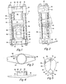
- FIG. 1 there is shown the crimping apparatus 10 of the invention and portions thereof, consisting in part of generally rectangular base plate 11 having a centrally located tapered throughbore 12 therein adapted for receipt of a die segment assembly 15 (not shown in Figures 1 and 2 for reasons of clarity).
- Base plate 11 is thus a die block with the throughbore 1 2 forming a die cavity therein of generally conical shape, having the larger opening at the upper surface 13 thereof for receipt of the die segment assembly 15.
- Base plate 11 is apertured at each corner for receipt of tie rods 16 which through apertures in turn in compression sleeves 18, trunnion caps 19 and cap plate 20, and are secured in tension by nuts 21.
- Generally rectangular cap plate 20, engaging each of the tie rods 16, serves to tie together the upper portion of the crimping machine 10.
- An upper cylinder support 22 is pivotally mounted between trunnion caps 19 in aligned bearing apertures 24 by means of laterally extending trunnion pins 25.
- a hydraulic actuator 26 consisting of hydraulic cylinder 28 and linearly movable piston rod 29 is supported for movement with upper cylinder support 22 by means of lower support plate 30, tie rods 31, and nuts 32.
- the hydraulic actuator 26 may be rocked between the normal forward crimping position shown in full lines in Figures 1 and 2 and the rearward clearance position shown in dahsed lines in Figure 2.
- a pusher device 34 consisting of a generally cylindrical hollow member having an opening 35 in the forward portion thereof is secured to the piston rod 29 for movement therewith and is the device for transmitting force to the die collet assembly 15.
- a pair of cam followers 38 consisting of rollers mounted on transversely extending shafts 39 are supported on opposite sides of pusher 34 to guide movement thereof and are positioned to ride upon the forward cam surface of a pair of cam plates 40, in turn extending generally vertically and supported at either side of pusher 34 on base plate 11, by means of bolts 41.
- Each cam plate 40 comprises a sturdy metal plate having a straight cam surface 42 extending upwardly from the base plate 11 to a location slightly below the uppermost retracted position of the end of ram 39. The cam surface 42 then curves into a rearwardly and slightly upwardly extending ramp portion 44 at an angle of approximately 80° to the line of the straight cam surface 42, terminating in a further rearward and straight upward cam stop surface 45.
- the cam followers 38 are positioned to ride along the cam surfaces of the plates 4 0 and in so doing guide the pusher 34, and the cylinder 28 therewith.
- the cam followers 38 When the cam followers 38 are in abutment with the straight cam surface 42, the pusher will be guided in a straight line between the line of the axis of the trunnion pins 25 and the center of base plate 11 at which tapered bore 12 is located, thus following the central axis of the bore 12.
- the cam followers 38 When in engagement with the ramp portion 44 the cam followers 38 will rock the pusher 24 and cylinder 28 between the full line and dashed line position shown in Figure 2. Rearward movement of the cam followers 38 is limited by the cam stop surface portion 45.
- bracket 46 secured to base plate II is provided for this purpose.
- the angled portion of bracket 46 may be mounted on a generally horizontal surface by means of bolts passing through aperture 47 to support the machine at an angle of about 15°.
- hydraulic actuator 26 will be urged by gravity toward the rearward position such that cam followers 38 will remain in contact with the cam surfaces of the cam plates 40 and be guided automatically between the full line and dashed line positions depicted in Figures land 2 as the ram 29 is extended and retracted.
- a die separator 50 comprises part of the crimping machine 10 and is shown in detail in Figures 3 and 4 as consisting 6f a tubular portion 51 integral with a generally flat, elongated mounting portion 52, extending from either side of the tubular portion 51 to span substantially the width of the base plate 11.
- the tubular portion 51 is of a diameter to freely fit within the smallest diameter of the tapered bore 12 and extends upwardly within the bore 12 approximately one-half the thickness of the base plate 11 when the mounting portion 52 is in engagement with the lower surface of the base plate 11.
- the die separator 50 is guided for movement into and out of the tapered bore 12 by means of the tubular portion 51 and is secured to the base plate 11 for such floating movement by means of a pair of extension springs 54.
- the springs 54 are disposed in bores in the base plate 11, between front and rear tie rods 16,
- Each die segment 62 further includes an inner cylindrical surface 71 parallel to the central axis and generally conforming to the shape of the socket 72 of a fitting 74 to be assembled to a hose 75.
- the inner surface 71 is adapted to contact the socket 72 to perform the crimping upon the latter and may be shaped in different configurations to provide any desired indentation of the socket 72.
- the upper surface 76 of the die segment is flat and perpendicular to the central axis of the assembly and intersects the inner and outer cylindrical surfaces 71 and 66 and the flat sides 64.
- a flat lower surface 78 is parallel to upper surface 76 and is joined to inner surface 71 by a fan-shaped, upwardly angled conical segment surface 79.
- each die segment 62 is further configured by a pair of inclined flat surfaces 80, angled generally circumferentially of the die segment assembly 15 to form a vee-shaped bottom projection 81 on each segment, and inclined radially upwardly to form the upwardly and inwardly sloping ridge 82 joining the outer wall 68 and a generally cylindrical lower wall 84.
- die segment 62 With this configuration of die segment 62 it is relatively easy to provide a die segment assembly 15 of any desired size range.
- the die segments 62 may be assembled into an array as shown in Figure 9, retained in place, and then drilled or bored along the central axis of the array to form the desired inner surfaces 71.
- An increased axial extent of inner surface 71 for larger diameter sizes is thus automatically provided by the point of intersection of surface 71 with angled conical surface 79.
- each die segment 62 is connected to an adjacent die segment 62 by means of an intermediate rigid link 85 consisting of an elongated metal loop disposed in adjacent slots 69 and pivotally secured in place by means of spring type link pins 86 pressed into drilled holes 70.
- Two adjacent die segments 62a, 62b are not linked together and thus form the first die segment 62a, and last die segment 62b, with intermediate die segments 62 in a unitary chain of die segments comprising the die segment assembly 15.
- An indentation 73 of a particular shape is included in the top surface 76 of each die segment 62 as a device for coding the die segment assembly 15.
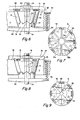
- a preassembled hose 75 having end fitting 74 thereon may be inserted from the bottom of the crimping machine 10 through the tubular portion 51 of die separator 50 to approximately the location shown in Figure 6.
- Die segment assembly 15 may then be dropped into the tapered bore 12 in base plate ll, being wrapped about the collar 72 of hose fitting 74 and resting upon die separator 50.
- Vee-shaped projections 81 of each die segment 62 will enter between the vee-shaped projections 59 of separator 50 such that the respective angled surfaces 80, 58 forming the projections, will interengage, spreading the individual die segments with equal spacing between them.
- each die segment 62 is at a greater distance from the centerline 65 of the tapered throughbore 12 than the inner end of the ridges 60, so that the die segments 62 are urged by gravity to fall outward against the intersection 67 of throughbore 12 and the upper surface 13 of base plate 11.
- the angle 83 between the bottom ridge 82 and the horizontal is greater than the angle of repose for the contacting plane surfaces 58 and 80, so that the die segments 62 are urged by gravity to slide outward against the throughbore 12. In their final position, the chain of die segments 62 are evenly spaced and fully retracted solely through the force of gravity.
- a pusher plate 36 having central aperture 90 therein may be placed over fitting 74 such that flat recessed surface 91 engages the top surfaces 76 of the die segments 62, further assuring vertical alignment and even spacing of the die segments 62, preparatory to crimping.
- the lower surface 92 of pusher plate 36 is separated in this preliminary position from the upper surface 13 of base plate 11.
- Figures 8 and 9 depict the condition of the elements upon completion of the crimp.
- pusher plate 36 had been engaged by pusher 34 and driven downwardly under urging of the hydraulic actuator 26, forcing the die segments 62 further downward into the tapered bore 12 and constricting same to a radial inward position.
- the inner surfaces 71 of the die segments 62 engaged the socket 72 of the hose fitting 74 and compressed same onto the end of inserted hose 75, until the final crimped diameter 93, depicted in Figure 9, was attained.
- die segments 62 may have adjacent faces 64 in engagement at this location, some spacing is normally provided, with the crimp diameter 93 being determined by the abutment of lower surface 92 of pusher plate 36 with the top surface 13 of base plate 11, this being the second or crimp position of the die assembly 15.
- die separator 50 has been forced downwardly against the bias of springs 54 to a position where surface portion 52 is spaced from the lower surface of base plate 11.
- die segments 62 Upon release of force by return of the pusher 34 to a retracted position, die segments 62 will be urged upwardly to the circumferentially and radially spaced position depicted in Figure 6 under the urging of springs 54.
Applications Claiming Priority (2)
| Application Number | Priority Date | Filing Date | Title |
|---|---|---|---|
| US06/145,158 US4309892A (en) | 1980-04-30 | 1980-04-30 | Crimping machine |
| US145158 | 1980-04-30 |
Publications (3)
| Publication Number | Publication Date |
|---|---|
| EP0039200A2 true EP0039200A2 (de) | 1981-11-04 |
| EP0039200A3 EP0039200A3 (en) | 1982-05-12 |
| EP0039200B1 EP0039200B1 (de) | 1985-07-17 |
Family
ID=22511854
Family Applications (1)
| Application Number | Title | Priority Date | Filing Date |
|---|---|---|---|
| EP81301780A Expired EP0039200B1 (de) | 1980-04-30 | 1981-04-22 | Radialpressmaschine |
Country Status (6)
| Country | Link |
|---|---|
| US (1) | US4309892A (de) |
| EP (1) | EP0039200B1 (de) |
| AU (1) | AU540759B2 (de) |
| CA (1) | CA1177229A (de) |
| DE (1) | DE3171377D1 (de) |
| ZA (1) | ZA812758B (de) |
Cited By (5)
| Publication number | Priority date | Publication date | Assignee | Title |
|---|---|---|---|---|
| EP0115467A1 (de) * | 1983-01-27 | 1984-08-08 | Hydraulic Engineering Inc. | Schlauchkupplungs-Klemmverbindungsvorrichtung und Verfahren zum Klemmverbinden |
| WO1985001897A1 (en) * | 1983-11-01 | 1985-05-09 | Parker-Hannifin Corporation | Crimping machine with split die ring |
| EP0147971A2 (de) * | 1983-12-23 | 1985-07-10 | Parker Hannifin Corporation | Stempelsegment mit geteilter Rückseite |
| GB2342305A (en) * | 1998-10-09 | 2000-04-12 | Dana Corp | Improved portable crimper |
| CN106077307A (zh) * | 2016-06-28 | 2016-11-09 | 芜湖通和汽车管路系统股份有限公司 | 一种用于汽车制动软管扣压的工装 |
Families Citing this family (13)
| Publication number | Priority date | Publication date | Assignee | Title |
|---|---|---|---|---|
| US4472959A (en) * | 1982-02-16 | 1984-09-25 | Grotnes Metalforming Systems, Inc. | Removable multi-die cartridge for shrink forming machine |
| US4781055A (en) * | 1985-11-18 | 1988-11-01 | Stratoflex, Inc. | Crimping machine |
| US4773249A (en) * | 1986-11-26 | 1988-09-27 | Dana Corporation | Hose fitting crimper |
| US4866973A (en) * | 1988-07-19 | 1989-09-19 | Dana Corporation | Pivotable mounting base for a collet crimping machine |
| US4887451A (en) * | 1988-08-10 | 1989-12-19 | Dana Corporation | Self-retracting modular collet assembly |
| US5044190A (en) * | 1990-09-04 | 1991-09-03 | Dana Corporation | Base for rotatably supporting a collet crimping machine |
| US5644945A (en) * | 1996-03-29 | 1997-07-08 | Caterpillar Inc. | Crimping die for use in a crimping machine |
| CA2447812C (en) | 2001-06-22 | 2010-02-09 | Parker-Hannifin Corporation | Portable crimping device for crimping fittings sockets |
| US7360304B2 (en) * | 2005-03-22 | 2008-04-22 | Parker-Hannifin Corporation | Folding stand for a portable crimping device |
| WO2008034132A1 (en) * | 2006-09-15 | 2008-03-20 | Parker-Hannifin Corporation | Compact crimping machine |
| CN101947606B (zh) * | 2010-08-26 | 2013-01-23 | 袁正敏 | 镶块模压式收口机 |
| US20130185909A1 (en) * | 2012-01-25 | 2013-07-25 | Apple Inc. | Apparatuses and methods for assembling components into assemblies using fixtures defining self-aligning surfaces |
| US20180193897A1 (en) * | 2017-01-12 | 2018-07-12 | UEMSI/HTV, Inc. | Portable hose fitting swaging device |
Citations (11)
| Publication number | Priority date | Publication date | Assignee | Title |
|---|---|---|---|---|
| US1552162A (en) * | 1921-07-26 | 1925-09-01 | Dodge Brothers Inc | Crimping tool |
| US3393549A (en) * | 1965-04-29 | 1968-07-23 | Walker Mfg Co | Tube machine |
| US3742754A (en) * | 1971-10-21 | 1973-07-03 | Weatherhead Co | Gaging device for crimping machine |
| US3750452A (en) * | 1971-10-07 | 1973-08-07 | Weatherhead Co | Collet crimper |
| US3762209A (en) * | 1972-05-08 | 1973-10-02 | Dayco Corp | Crimping apparatus |
| US3787950A (en) * | 1972-03-01 | 1974-01-29 | Caterpillar Tractor Co | Apparatus for reclaiming collet hose fittings |
| DE2214339B2 (de) * | 1972-03-24 | 1976-01-08 | Elga 6000 Frankfurt Schroeck Geb. Bechtel | Presse zum Befestigen von Armaturen an Schlauchleitungen |
| US4034593A (en) * | 1976-04-09 | 1977-07-12 | The Weatherhead Company | Crimping machine with automatic swing open pushers |
| US4034592A (en) * | 1976-03-31 | 1977-07-12 | The Weatherhead Company | Crimping machine with automatic hinge open pushers |
| US4050286A (en) * | 1976-10-15 | 1977-09-27 | Parker-Hannifin Corporation | Swaging apparatus |
| US4244093A (en) * | 1979-03-19 | 1981-01-13 | Fred Klingensmith | Tubing slip pulling tool |
Family Cites Families (4)
| Publication number | Priority date | Publication date | Assignee | Title |
|---|---|---|---|---|
| US3335594A (en) * | 1965-03-25 | 1967-08-15 | Imp Eastman Corp | Crimping apparatus |
| US3720088A (en) * | 1971-04-29 | 1973-03-13 | Weatherhead Co | Split collet crimper |
| US3851514A (en) * | 1973-07-18 | 1974-12-03 | Weatherhead Co | Swing-open crimper |
| GB1484515A (en) * | 1975-04-16 | 1977-09-01 | Imp Eastman Ltd | Crimping apparatus |
-
1980
- 1980-04-30 US US06/145,158 patent/US4309892A/en not_active Expired - Lifetime
-
1981
- 1981-04-22 EP EP81301780A patent/EP0039200B1/de not_active Expired
- 1981-04-22 CA CA000375938A patent/CA1177229A/en not_active Expired
- 1981-04-22 DE DE8181301780T patent/DE3171377D1/de not_active Expired
- 1981-04-23 AU AU69753/81A patent/AU540759B2/en not_active Expired
- 1981-04-27 ZA ZA00812758A patent/ZA812758B/xx unknown
Patent Citations (11)
| Publication number | Priority date | Publication date | Assignee | Title |
|---|---|---|---|---|
| US1552162A (en) * | 1921-07-26 | 1925-09-01 | Dodge Brothers Inc | Crimping tool |
| US3393549A (en) * | 1965-04-29 | 1968-07-23 | Walker Mfg Co | Tube machine |
| US3750452A (en) * | 1971-10-07 | 1973-08-07 | Weatherhead Co | Collet crimper |
| US3742754A (en) * | 1971-10-21 | 1973-07-03 | Weatherhead Co | Gaging device for crimping machine |
| US3787950A (en) * | 1972-03-01 | 1974-01-29 | Caterpillar Tractor Co | Apparatus for reclaiming collet hose fittings |
| DE2214339B2 (de) * | 1972-03-24 | 1976-01-08 | Elga 6000 Frankfurt Schroeck Geb. Bechtel | Presse zum Befestigen von Armaturen an Schlauchleitungen |
| US3762209A (en) * | 1972-05-08 | 1973-10-02 | Dayco Corp | Crimping apparatus |
| US4034592A (en) * | 1976-03-31 | 1977-07-12 | The Weatherhead Company | Crimping machine with automatic hinge open pushers |
| US4034593A (en) * | 1976-04-09 | 1977-07-12 | The Weatherhead Company | Crimping machine with automatic swing open pushers |
| US4050286A (en) * | 1976-10-15 | 1977-09-27 | Parker-Hannifin Corporation | Swaging apparatus |
| US4244093A (en) * | 1979-03-19 | 1981-01-13 | Fred Klingensmith | Tubing slip pulling tool |
Cited By (8)
| Publication number | Priority date | Publication date | Assignee | Title |
|---|---|---|---|---|
| EP0115467A1 (de) * | 1983-01-27 | 1984-08-08 | Hydraulic Engineering Inc. | Schlauchkupplungs-Klemmverbindungsvorrichtung und Verfahren zum Klemmverbinden |
| US4515006A (en) * | 1983-01-27 | 1985-05-07 | The Goodyear Tire & Rubber Company | Hose coupling crimper and method of crimping |
| WO1985001897A1 (en) * | 1983-11-01 | 1985-05-09 | Parker-Hannifin Corporation | Crimping machine with split die ring |
| EP0147971A2 (de) * | 1983-12-23 | 1985-07-10 | Parker Hannifin Corporation | Stempelsegment mit geteilter Rückseite |
| EP0147971A3 (en) * | 1983-12-23 | 1987-01-28 | Parker Hannifin Corporation | Split back die segment |
| GB2342305A (en) * | 1998-10-09 | 2000-04-12 | Dana Corp | Improved portable crimper |
| GB2342305B (en) * | 1998-10-09 | 2002-11-06 | Dana Corp | Improved portable crimper |
| CN106077307A (zh) * | 2016-06-28 | 2016-11-09 | 芜湖通和汽车管路系统股份有限公司 | 一种用于汽车制动软管扣压的工装 |
Also Published As
| Publication number | Publication date |
|---|---|
| AU540759B2 (en) | 1984-12-06 |
| AU6975381A (en) | 1981-11-05 |
| EP0039200B1 (de) | 1985-07-17 |
| ZA812758B (en) | 1982-04-28 |
| DE3171377D1 (en) | 1985-08-22 |
| US4309892A (en) | 1982-01-12 |
| EP0039200A3 (en) | 1982-05-12 |
| CA1177229A (en) | 1984-11-06 |
Similar Documents
| Publication | Publication Date | Title |
|---|---|---|
| US4309892A (en) | Crimping machine | |
| US3750452A (en) | Collet crimper | |
| US4516296A (en) | Tubing clamp and method of making the same | |
| US4854031A (en) | Hose crimper and method of using same | |
| US4183132A (en) | Elastic ring fitting device | |
| US6354606B1 (en) | Chuck adapter assembly and related method for converting a fixed chuck to a compensating chuck | |
| EP0451417A2 (de) | Einbördelmaschine | |
| US8230714B2 (en) | Die carrier assembly and crimping process | |
| EP0156575B1 (de) | Klemme | |
| EP1090244B1 (de) | Geschlitzte krimpmatrize für krimpvorrichtung | |
| EP0041302A1 (de) | Verfahren und Vorrichtung zum Herstellen eines Dosenkörpers mit mindestens, an einer offenen Seite, einem nach aussen gerichteten kreisförmigen Flansch und eine daran anschliessende Nut | |
| US4703548A (en) | Apparatus for fitting O-rings onto workpieces | |
| US4781566A (en) | Apparatus and related method for aligning irregular blanks relative to a die half | |
| EP0160090B1 (de) | Sickengerät | |
| EP0147971B1 (de) | Stempelsegment mit geteilter Rückseite | |
| US5515710A (en) | Device for flaring out pipes | |
| CA1245834A (en) | Heavy duty hose crimper | |
| US4532706A (en) | Retaining ring assembly machine | |
| US6116845A (en) | Apparatus for supporting a workpiece for transfer | |
| IE60104B1 (en) | Process and apparatus for manufacturing pipe fittings | |
| EP0084713B1 (de) | Crimp-Anschlag | |
| US7383714B2 (en) | Crimp machine with quick release pushers | |
| MXPA00012422A (en) | Slotted crimping die for use in a crimping machine |
Legal Events
| Date | Code | Title | Description |
|---|---|---|---|
| PUAI | Public reference made under article 153(3) epc to a published international application that has entered the european phase |
Free format text: ORIGINAL CODE: 0009012 |
|
| AK | Designated contracting states |
Designated state(s): DE FR GB IT |
|
| RBV | Designated contracting states (corrected) |
Designated state(s): DE FR GB IT |
|
| PUAL | Search report despatched |
Free format text: ORIGINAL CODE: 0009013 |
|
| AK | Designated contracting states |
Designated state(s): DE FR GB IT |
|
| 17P | Request for examination filed |
Effective date: 19820927 |
|
| ITF | It: translation for a ep patent filed |
Owner name: ST. ASSOC. MARIETTI & PIPPARELLI |
|
| GRAA | (expected) grant |
Free format text: ORIGINAL CODE: 0009210 |
|
| AK | Designated contracting states |
Designated state(s): DE FR GB IT |
|
| REF | Corresponds to: |
Ref document number: 3171377 Country of ref document: DE Date of ref document: 19850822 |
|
| ET | Fr: translation filed | ||
| RAP2 | Party data changed (patent owner data changed or rights of a patent transferred) |
Owner name: PARKER HANNIFIN CORPORATION |
|
| PLBE | No opposition filed within time limit |
Free format text: ORIGINAL CODE: 0009261 |
|
| STAA | Information on the status of an ep patent application or granted ep patent |
Free format text: STATUS: NO OPPOSITION FILED WITHIN TIME LIMIT |
|
| 26N | No opposition filed | ||
| ITTA | It: last paid annual fee | ||
| PGFP | Annual fee paid to national office [announced via postgrant information from national office to epo] |
Ref country code: FR Payment date: 20000313 Year of fee payment: 20 |
|
| PGFP | Annual fee paid to national office [announced via postgrant information from national office to epo] |
Ref country code: GB Payment date: 20000321 Year of fee payment: 20 |
|
| PGFP | Annual fee paid to national office [announced via postgrant information from national office to epo] |
Ref country code: DE Payment date: 20000324 Year of fee payment: 20 |
|
| PG25 | Lapsed in a contracting state [announced via postgrant information from national office to epo] |
Ref country code: GB Free format text: LAPSE BECAUSE OF EXPIRATION OF PROTECTION Effective date: 20010421 |
|
| REG | Reference to a national code |
Ref country code: GB Ref legal event code: PE20 Effective date: 20010421 |