EP0039176B1 - Passive safety belt system - Google Patents
Passive safety belt system Download PDFInfo
- Publication number
- EP0039176B1 EP0039176B1 EP81301669A EP81301669A EP0039176B1 EP 0039176 B1 EP0039176 B1 EP 0039176B1 EP 81301669 A EP81301669 A EP 81301669A EP 81301669 A EP81301669 A EP 81301669A EP 0039176 B1 EP0039176 B1 EP 0039176B1
- Authority
- EP
- European Patent Office
- Prior art keywords
- point
- safety belt
- vehicle
- door
- seat
- Prior art date
- Legal status (The legal status is an assumption and is not a legal conclusion. Google has not performed a legal analysis and makes no representation as to the accuracy of the status listed.)
- Expired
Links
Images



Classifications
-
- B—PERFORMING OPERATIONS; TRANSPORTING
- B60—VEHICLES IN GENERAL
- B60R—VEHICLES, VEHICLE FITTINGS, OR VEHICLE PARTS, NOT OTHERWISE PROVIDED FOR
- B60R22/00—Safety belts or body harnesses in vehicles
- B60R22/04—Passive restraint systems, i.e. systems both applied and removed automatically, e.g. by movement of the vehicle door
Definitions
- This invention relates to a motor vehicle having a fascia forward of its steering wheel, a seat located adjacent to a front hinged door and a passive safety belt system comprising a shoulder strap, a lap strap and a common strap interconnected to form a three-point safety belt, the free ends of the shoulder and lap straps being connected to the rear edge of the vehicle door in proximity to the top and bottom corners thereof respectively and the common strap being guided, at a location on the vehicle inboard of and adjacent to the bottom of the back of the seat, on to an inertia reel, and puller means interconnecting a point on the safety belt with a point on the vehicle.
- GB-A-1412013 discloses a passive safety belt system of this type.
- the puller means is connected to a traveller mounted on a track on the vehicle door.
- the present invention avoids the need for such a traveller and track.
- the puller means is fastened to a point on the safety belt which is inboard of the seat when the door is closed and connects the said point to a point on the vehicle in front of and above the normal position of the knees of an occupant of the seat and closely adjacent to the fascia when the door is opened, thereby to displace the junction between the lap, shoulder and common straps out of the plane containing the rear edge of the vehicle door and the location in a direction away from the seat.
- the point on the vehicle to which the puller means is connected may be a fixed location on the fascia immediately below the windscreen.
- the point may be movable, for example in the form of a slider mounted on a track, the end of which nearer to the door is higher than the other end, or the end of an arm mounted on a transverse pivot axis, the end of which nearer the door is lower than the other end.
- the lap and shoulder straps are formed as a single continuous length running freely through a guide member which is attached to the end of the common strap, and the puller means comprises a flexible element running freely through the guide member and attached to the shoulder strap at a point spaced from the guide member.
- the guide member may comprise a ring which need not be circular. Alternatively, it may be a more complex component having separate apertures for the lap and shoulder straps and the puller member respectively.
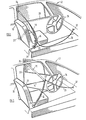
- FIGS 1 and 2 show the driver's seat 10 of a motor car 12 in accordance with the invention.
- a safety belt for the driver consists of a single length of webbing, forming the lap element 14 and the diagonal element 16 which runs freely through a flattened ring 18 connected to one end of another length of webbing forming the common element 20 of the safety belt.
- the free ends of the lap and diagonal elements 14 and 16 are connected to respective anchorages 22 and 24 near the bottom and top rear corners of the adjacent door 26 of the car.
- the free end of the common element 20 is connected to an inertia reel 28 mounted on the floor of the car on the inboard side of the seat 10 and adjacent to the back thereof.
- a piece of webbing 30 is connected between a point on the common element 20 adjacent to the ring 18 and a point 32 in the centre of the fascia just below the windscreen.
- the length of the webbing 30 is chosen so that it hangs in a position so as not to obstruct access to the handbrake and gear lever (not shown).
- the safety belt comprising the elements 14, 16 and 20 is in a configuration to be used by the driver of the car 12 and is not affected by the piece of webbing 30.
- the resulting pull on the lap and diagonal elements 14 and 16, particularly the latter causes webbing to be drawn off the reel 28.
- the piece of webbing 30 has no effect but, when it tightens, it pulls the ring 18 and the adjacent elements of the safety belt away from the body of the driver until, when the door 26 is fully open, the safety belt is in the configuration shown in Figure 2.
- a similar system may be provided for the front seat passenger.
- the choice of the length of the piece of webbing 30 is a compromise between not interfering with access to the handbrake and gear lever when the car door 26 is closed, which dictates that the length shall be as long as convenient, and maximising the extent to which the safety belt is pulled away from the body of the driver when the door 26 is open, which dictates that the length should preferably be no longer than the distance between the point 32 and the rim of the steering wheel 34.
- This compromise can be improved by replacing the fixed anchorage point 32 with a movable anchorage point.
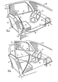
- FIGS 3 and 4 illustrate an alternative arrangement in which a movable anchorage point is provided, as applied to a car 40.
- Those parts of the system which are equivalent to corresponding parts of the system shown in Figures 1 and 2 are denoted by the same reference numerals and will not be described in detail.
- the movable anchorage takes the form of a slider 42 mounted on a track member 44 which, together with a corresponding track member 46 of an equivalent system for the front passenger's seat (not shown) forms a V-shape projecting rearwardly and downwardly from the fascia.
- the slider 42 is connected to a point on the common element 20 of the safety belt adjacent to the ring 18 by a cranked rigid member 48 having a long limb 50 which, when the car door 26 is closed, as shown in Figure 3, extends substantially forwardly from the common element 20 and a short limb 52 which is attached to the slider 42.
- the cranked member 48 When the car door 26 is opened, webbing is pulled off the reel 28 as before.
- the cranked member 48 is lifted up by the safety belt and the slider 42 travels along the track 44 until the cranked member 48 abuts against the steering wheel 34.
- the cranked member 48 then pivots on the edge of the steering wheel 34, to bring the short limb 52 thereof to a more horizontal orientation with the result that the end of the long limb 50 which is attached to the safety belt is drawn forwardly towards the steering wheel.
- the cranked configuration of the member 48 serves both to improve access to the handbrake and gear lever (not shown) and to increase the distance by which the safety belt is drawn away from the body of the driver.
- the rigid member 48 may be replaced by a piece of webbing or other flexible connecting material if desired. Similarly, a rigid member may be used with the system of Figures 1 and 2.
- FIGS 5 and 6 illustrate a car 60 fitted with another system in accordance with the invention.
- those parts which are equivalents to parts of the system shown in Figures 1 and 2 are denoted by the same reference numerals and will not be described in detail.
- the V-shaped track arrangement, 44, 46 of the system shown in Figures 3 and 4 is replaced by an S-shaped track arrangement consisting of track members 62 and 64.
- the track member 62 carries a slider 66 which is connected by a piece of webbing 68 to the common element 20 of the safety belt adjacent to the ring 18.
- the track member 64 carries a slider (not shown) for a corresponding system for the front passenger's seat.
- the operation of the system is similar to that of the system shown in Figures 3 and 4.
- the crossing track members 62 and 64 not interfering with the operation because the webbing 68 extends from the slider 66 approximately in the plane of the X-shape.
- the webbing 68 may be replaced by a rigid member suitably shaped to avoid interfering with the track member 64.
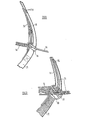
- FIGs 7, 8 and 9 illustrate a car 70 fitted with a further system in accordance with the invention.
- those parts which are equivalent to corresponding parts of the system shown in Figures 1 and 2 are denoted by the same reference numerals and will not be described in detail.
- the V-shaped track arrangement 44, 46 of the system shown in Figures 3 and 4 is replaced by a similar track arrangement, consisting of two track members of which only the track member 72 is illustrated.
- the track member 72 is curved so that although its upper end region follows substantially the same path as that of the track member 44, its lower end region is displaced forwardly so as not to project as far back in the car towards the seats.
- the track member 72 carries a slider 74 which is connected to a piece of webbing 76.
- the piece of webbing 76 is threaded through the ring 18 and stitched to the diagonal element 16 at a point 78 ( Figure 9) which is spaced apart from the ring 18.
- Figure 9 shows the parts of the safety belt immediately adjacent to the ring in more detail, with the door in a half open position. It will be seen that the flexible element 76 is stitched to the side of the diagonal element 16 which faces the user's body so as to be appropriately positioned to run through the ring 18 without interfering with the co-operation between the latter and the three elements 14, 16 and 20 of the safety belt when the door is closed.
- Figure 10 illustrates an alternative guide member 80 for connecting the three elements of the safety belt and the piece of webbing 76 for use in place of the ring 18.
- the guide member 80 consists of a ring having a cross-bar 82 thereby providing three separate transverse elements round which the lap and diagonal elements 14 and 16, the common element 20 and the piece of webbing 76 can be led. This allows the piece of webbing 76 to be stitched, at a point 84, on the opposite side to that of the user's body in use.
- FIGs 11 and 12 illustrate a car 90 fitted with another system in accordance with the invention.
- those parts which are equivalent to corresponding parts of the system shown in Figures 1 and 2 are denoted by the same reference numerals and will not be described in detail.
- the curved track members of the system shown in Figures 7 and 8 are replaced by a cranked lever 92 which is pivotally mounted beneath the fascia 94 of the car 90.
- the fascia 94 is shown broken away and, as can be seen, the axle 96 on which the lever 92 is mounted extends generally transversely of the car 90 but its end nearer the door 26 is lower than its other end. The effect of this is that, as the lever 92 pivots upwardly from the position shown in Figure 11 to the position shown in Figure 12, its outer end 98 moves closer to the door 26.
- the free end 98 of the lever 92 is connected to the ring 18 by a piece of webbing 100, similar to the piece of webbing 76 of Figures 7 and 8.
- the piece of webbing 100 extends through the ring 18 and is stitched to the diagonal element 16 at a point spaced apart from the ring 18, in a similar manner to that described with reference to Figures 9 or 10.
- the diagonal element 16 of the safety belt pulls on the piece of webbing 100 which in turn pulls on the free end 98 of the lever 92.
- the piece of webbing 100 exerts a force on the lever 92 with a sufficient component in a direction perpendicular to the axle 96 for the lever 92 to be lifted from the position shown in Figure 11 to the position shown in Figure 12.
- the cranked formation of the lever 92 enables it to perform this movement without being obstructed by the fascia 94.
- the free end 98 of the lever 92 thus follows a similar path to that of the slider 74 of Figures 7 and 8 but the system shown in Figures 11 and 12 has the advantage that it can be installed without requiring any modification of the fascia 94.
Landscapes
- Engineering & Computer Science (AREA)
- Mechanical Engineering (AREA)
- Automotive Seat Belt Assembly (AREA)
Description
- This invention relates to a motor vehicle having a fascia forward of its steering wheel, a seat located adjacent to a front hinged door and a passive safety belt system comprising a shoulder strap, a lap strap and a common strap interconnected to form a three-point safety belt, the free ends of the shoulder and lap straps being connected to the rear edge of the vehicle door in proximity to the top and bottom corners thereof respectively and the common strap being guided, at a location on the vehicle inboard of and adjacent to the bottom of the back of the seat, on to an inertia reel, and puller means interconnecting a point on the safety belt with a point on the vehicle.
- GB-A-1412013 discloses a passive safety belt system of this type. The puller means is connected to a traveller mounted on a track on the vehicle door. The present invention avoids the need for such a traveller and track.
- According to the invention, in a system of this type, the puller means is fastened to a point on the safety belt which is inboard of the seat when the door is closed and connects the said point to a point on the vehicle in front of and above the normal position of the knees of an occupant of the seat and closely adjacent to the fascia when the door is opened, thereby to displace the junction between the lap, shoulder and common straps out of the plane containing the rear edge of the vehicle door and the location in a direction away from the seat.
- The point on the vehicle to which the puller means is connected may be a fixed location on the fascia immediately below the windscreen. Alternatively, the point may be movable, for example in the form of a slider mounted on a track, the end of which nearer to the door is higher than the other end, or the end of an arm mounted on a transverse pivot axis, the end of which nearer the door is lower than the other end.
- In a preferred form of the invention the lap and shoulder straps are formed as a single continuous length running freely through a guide member which is attached to the end of the common strap, and the puller means comprises a flexible element running freely through the guide member and attached to the shoulder strap at a point spaced from the guide member. The guide member may comprise a ring which need not be circular. Alternatively, it may be a more complex component having separate apertures for the lap and shoulder straps and the puller member respectively.
- Embodiments of the invention will now be described, by way of example, with reference to the accompanying drawings, in which:
- Figures 1 and 2 are perspective views of the interior of a motor car in accordance with a first embodiment of the invention, with the door adjacent to the seat provided with the safety belt closed and open respectively;
- Figures 3 and 4 are perspective views, corresponding to Figures 1 and 2, of a second embodiment of the invention,
- Figures 5 and 6 are perspective views, corresponding to Figures 1 and 2, of a third embodiment of the invention;
- Figures 7 and 8 are perspective views, corresponding to Figures 1 and 2, of a fourth embodiment of the invention;
- Figures 9 and 10 are perspective views, illustrating two alternative forms of guide member for use with the embodiment shown in Figures 7 and 8; and
- Figures 11 and 12 are perspective views, corresponding to Figures 1 and 2, of a fifth embodiment of the invention.
- Figures 1 and 2 show the driver's
seat 10 of amotor car 12 in accordance with the invention. A safety belt for the driver consists of a single length of webbing, forming thelap element 14 and thediagonal element 16 which runs freely through aflattened ring 18 connected to one end of another length of webbing forming thecommon element 20 of the safety belt. The free ends of the lap anddiagonal elements respective anchorages adjacent door 26 of the car. The free end of thecommon element 20 is connected to aninertia reel 28 mounted on the floor of the car on the inboard side of theseat 10 and adjacent to the back thereof. - In accordance with the invention, a piece of
webbing 30 is connected between a point on thecommon element 20 adjacent to thering 18 and apoint 32 in the centre of the fascia just below the windscreen. The length of thewebbing 30 is chosen so that it hangs in a position so as not to obstruct access to the handbrake and gear lever (not shown). - When the
car door 26 is closed, the safety belt comprising theelements car 12 and is not affected by the piece ofwebbing 30. When thedoor 26 is opened the resulting pull on the lap anddiagonal elements reel 28. Initially the piece ofwebbing 30 has no effect but, when it tightens, it pulls thering 18 and the adjacent elements of the safety belt away from the body of the driver until, when thedoor 26 is fully open, the safety belt is in the configuration shown in Figure 2. - A similar system may be provided for the front seat passenger.
- It will be appreciated that the choice of the length of the piece of
webbing 30 is a compromise between not interfering with access to the handbrake and gear lever when thecar door 26 is closed, which dictates that the length shall be as long as convenient, and maximising the extent to which the safety belt is pulled away from the body of the driver when thedoor 26 is open, which dictates that the length should preferably be no longer than the distance between thepoint 32 and the rim of thesteering wheel 34. This compromise can be improved by replacing thefixed anchorage point 32 with a movable anchorage point. - Figures 3 and 4 illustrate an alternative arrangement in which a movable anchorage point is provided, as applied to a
car 40. Those parts of the system which are equivalent to corresponding parts of the system shown in Figures 1 and 2 are denoted by the same reference numerals and will not be described in detail. - The movable anchorage takes the form of a
slider 42 mounted on atrack member 44 which, together with acorresponding track member 46 of an equivalent system for the front passenger's seat (not shown) forms a V-shape projecting rearwardly and downwardly from the fascia. Theslider 42 is connected to a point on thecommon element 20 of the safety belt adjacent to thering 18 by a crankedrigid member 48 having along limb 50 which, when thecar door 26 is closed, as shown in Figure 3, extends substantially forwardly from thecommon element 20 and ashort limb 52 which is attached to theslider 42. - When the
car door 26 is opened, webbing is pulled off thereel 28 as before. The crankedmember 48 is lifted up by the safety belt and theslider 42 travels along thetrack 44 until thecranked member 48 abuts against thesteering wheel 34. The crankedmember 48 then pivots on the edge of thesteering wheel 34, to bring theshort limb 52 thereof to a more horizontal orientation with the result that the end of thelong limb 50 which is attached to the safety belt is drawn forwardly towards the steering wheel. Thus the cranked configuration of themember 48 serves both to improve access to the handbrake and gear lever (not shown) and to increase the distance by which the safety belt is drawn away from the body of the driver. - The
rigid member 48 may be replaced by a piece of webbing or other flexible connecting material if desired. Similarly, a rigid member may be used with the system of Figures 1 and 2. - Figures 5 and 6 illustrate a
car 60 fitted with another system in accordance with the invention. Once again, those parts which are equivalents to parts of the system shown in Figures 1 and 2 are denoted by the same reference numerals and will not be described in detail. - The V-shaped track arrangement, 44, 46 of the system shown in Figures 3 and 4 is replaced by an S-shaped track arrangement consisting of
track members track member 62 carries aslider 66 which is connected by a piece ofwebbing 68 to thecommon element 20 of the safety belt adjacent to thering 18. Thetrack member 64 carries a slider (not shown) for a corresponding system for the front passenger's seat. The operation of the system is similar to that of the system shown in Figures 3 and 4. Thecrossing track members webbing 68 extends from theslider 66 approximately in the plane of the X-shape. - The
webbing 68 may be replaced by a rigid member suitably shaped to avoid interfering with thetrack member 64. - Figures 7, 8 and 9 illustrate a
car 70 fitted with a further system in accordance with the invention. Once again, those parts which are equivalent to corresponding parts of the system shown in Figures 1 and 2 are denoted by the same reference numerals and will not be described in detail. - The V-
shaped track arrangement track member 72 is illustrated. Thetrack member 72 is curved so that although its upper end region follows substantially the same path as that of thetrack member 44, its lower end region is displaced forwardly so as not to project as far back in the car towards the seats. Thetrack member 72 carries aslider 74 which is connected to a piece ofwebbing 76. The piece ofwebbing 76 is threaded through thering 18 and stitched to thediagonal element 16 at a point 78 (Figure 9) which is spaced apart from thering 18. - When the
door 26 is fully open, as shown in Figure 8, the piece ofwebbing 76 pulls some of thediagonal element 16 through thering 18 so as to effectively increase the length of thelap element 14. This prevents thelap element 14 from pulling thering 18 downwards, with the result that it is located substantially on a straight line between theslider 74 and theanchorage 24 at the top rear corner of the door 26 (compare Figure 6). - Figure 9 shows the parts of the safety belt immediately adjacent to the ring in more detail, with the door in a half open position. It will be seen that the
flexible element 76 is stitched to the side of thediagonal element 16 which faces the user's body so as to be appropriately positioned to run through thering 18 without interfering with the co-operation between the latter and the threeelements - Figure 10 illustrates an
alternative guide member 80 for connecting the three elements of the safety belt and the piece ofwebbing 76 for use in place of thering 18. Theguide member 80 consists of a ring having across-bar 82 thereby providing three separate transverse elements round which the lap anddiagonal elements common element 20 and the piece ofwebbing 76 can be led. This allows the piece ofwebbing 76 to be stitched, at apoint 84, on the opposite side to that of the user's body in use. - Figures 11 and 12 illustrate a
car 90 fitted with another system in accordance with the invention. Once again, those parts which are equivalent to corresponding parts of the system shown in Figures 1 and 2 are denoted by the same reference numerals and will not be described in detail. - The curved track members of the system shown in Figures 7 and 8 are replaced by a
cranked lever 92 which is pivotally mounted beneath thefascia 94 of thecar 90. Thefascia 94 is shown broken away and, as can be seen, theaxle 96 on which thelever 92 is mounted extends generally transversely of thecar 90 but its end nearer thedoor 26 is lower than its other end. The effect of this is that, as thelever 92 pivots upwardly from the position shown in Figure 11 to the position shown in Figure 12, itsouter end 98 moves closer to thedoor 26. Thefree end 98 of thelever 92 is connected to thering 18 by a piece ofwebbing 100, similar to the piece of webbing 76 of Figures 7 and 8. Preferably, the piece ofwebbing 100 extends through thering 18 and is stitched to thediagonal element 16 at a point spaced apart from thering 18, in a similar manner to that described with reference to Figures 9 or 10. - When the
door 26 is opened, thediagonal element 16 of the safety belt pulls on the piece ofwebbing 100 which in turn pulls on thefree end 98 of thelever 92. Because of the downward slope of theaxle 96, the piece ofwebbing 100 exerts a force on thelever 92 with a sufficient component in a direction perpendicular to theaxle 96 for thelever 92 to be lifted from the position shown in Figure 11 to the position shown in Figure 12. The cranked formation of thelever 92 enables it to perform this movement without being obstructed by thefascia 94. Thefree end 98 of thelever 92 thus follows a similar path to that of theslider 74 of Figures 7 and 8 but the system shown in Figures 11 and 12 has the advantage that it can be installed without requiring any modification of thefascia 94.
Claims (5)
Applications Claiming Priority (8)
| Application Number | Priority Date | Filing Date | Title |
|---|---|---|---|
| GB8014198 | 1980-04-30 | ||
| GB8014198 | 1980-04-30 | ||
| GB8015857 | 1980-05-13 | ||
| GB8015857 | 1980-05-13 | ||
| GB8029601 | 1980-09-12 | ||
| GB8029601 | 1980-09-12 | ||
| GB8032288 | 1980-10-08 | ||
| GB8032288 | 1980-10-08 |
Publications (2)
| Publication Number | Publication Date |
|---|---|
| EP0039176A1 EP0039176A1 (en) | 1981-11-04 |
| EP0039176B1 true EP0039176B1 (en) | 1984-09-12 |
Family
ID=27449174
Family Applications (1)
| Application Number | Title | Priority Date | Filing Date |
|---|---|---|---|
| EP81301669A Expired EP0039176B1 (en) | 1980-04-30 | 1981-04-15 | Passive safety belt system |
Country Status (4)
| Country | Link |
|---|---|
| EP (1) | EP0039176B1 (en) |
| AU (1) | AU536492B2 (en) |
| DE (1) | DE3165938D1 (en) |
| ES (1) | ES271589Y (en) |
Family Cites Families (6)
| Publication number | Priority date | Publication date | Assignee | Title |
|---|---|---|---|---|
| US3727944A (en) * | 1971-07-28 | 1973-04-17 | Gen Motors Corp | Control belt system for a vehicle body occupant restraining belt arrangement |
| FR2159748A5 (en) * | 1971-11-10 | 1973-06-22 | Peugeot & Renault | |
| DE2214776C3 (en) * | 1972-03-25 | 1978-03-23 | Adam Opel Ag, 6090 Ruesselsheim | Three-point seat belt system for vehicles, in particular for motor vehicles |
| FR2407002A1 (en) * | 1977-10-28 | 1979-05-25 | Peugeot | PASSIVE SECURITY STRAP FOR AUTOMOTIVE VEHICLES |
| US4189170A (en) * | 1978-04-05 | 1980-02-19 | American Safety Equipment Corporation | Three-point passive safety belt system |
| US4201401A (en) * | 1979-03-26 | 1980-05-06 | General Motors Corporation | Passive lap and shoulder belt system |
-
1981
- 1981-04-15 DE DE8181301669T patent/DE3165938D1/en not_active Expired
- 1981-04-15 EP EP81301669A patent/EP0039176B1/en not_active Expired
- 1981-04-23 AU AU69775/81A patent/AU536492B2/en not_active Ceased
- 1981-04-24 ES ES1981271589U patent/ES271589Y/en not_active Expired
Also Published As
| Publication number | Publication date |
|---|---|
| AU536492B2 (en) | 1984-05-10 |
| AU6977581A (en) | 1981-11-05 |
| DE3165938D1 (en) | 1984-10-18 |
| ES271589Y (en) | 1984-06-16 |
| ES271589U (en) | 1983-12-01 |
| EP0039176A1 (en) | 1981-11-04 |
Similar Documents
| Publication | Publication Date | Title |
|---|---|---|
| US5022677A (en) | Motor vehicle seat featuring two seat belts | |
| US5431446A (en) | Seat belt presenter | |
| US5332290A (en) | Seat belt load transfer mechanism for bench seat | |
| US4635963A (en) | Seat belt device | |
| US6224105B1 (en) | Arrangement for safety-belt | |
| EP0175493B1 (en) | Seat belt device for a vehicle | |
| US4258933A (en) | Movable inboard belt guide for use in passive vehicle occupant restraint systems | |
| US4124224A (en) | Seat belt system | |
| US4405155A (en) | Seat belt device for an automotive vehicle | |
| US4416469A (en) | Passive safety belt system | |
| US4291899A (en) | Vehicle occupant restraining safety apparatus | |
| US4323267A (en) | Passive vehicle seat belt system | |
| US3371942A (en) | Combination seat belt and upper torso restraint | |
| US4417751A (en) | Passive safety belt system | |
| US4193614A (en) | Passive restraining belt for seated vehicle occupant | |
| US4423887A (en) | Passive safety belt system | |
| EP0039176A1 (en) | Passive safety belt system | |
| US4218075A (en) | Passive seat belt system having lap belt lifter | |
| US3958812A (en) | Partially self-fastening, highly effective three-point safety belt for the occupants of vehicles | |
| KR0124363Y1 (en) | A device for depositing a buckle of a rear seat belt in a car | |
| JPH0580924U (en) | Suspension seat belt anchor structure | |
| GB2247606A (en) | Motor vehicle seat harness including lap straps | |
| EP0374973A2 (en) | Motor vehicle seat fitted with a seat belt | |
| US4230342A (en) | Passive seat belt system | |
| GB2086209A (en) | Passive safety belt system |
Legal Events
| Date | Code | Title | Description |
|---|---|---|---|
| PUAI | Public reference made under article 153(3) epc to a published international application that has entered the european phase |
Free format text: ORIGINAL CODE: 0009012 |
|
| AK | Designated contracting states |
Designated state(s): DE FR GB IT SE |
|
| 17P | Request for examination filed |
Effective date: 19820420 |
|
| ITF | It: translation for a ep patent filed | ||
| GRAA | (expected) grant |
Free format text: ORIGINAL CODE: 0009210 |
|
| AK | Designated contracting states |
Designated state(s): DE FR GB IT SE |
|
| REF | Corresponds to: |
Ref document number: 3165938 Country of ref document: DE Date of ref document: 19841018 |
|
| ET | Fr: translation filed | ||
| PLBE | No opposition filed within time limit |
Free format text: ORIGINAL CODE: 0009261 |
|
| STAA | Information on the status of an ep patent application or granted ep patent |
Free format text: STATUS: NO OPPOSITION FILED WITHIN TIME LIMIT |
|
| 26N | No opposition filed | ||
| PG25 | Lapsed in a contracting state [announced via postgrant information from national office to epo] |
Ref country code: SE Effective date: 19860416 |
|
| PG25 | Lapsed in a contracting state [announced via postgrant information from national office to epo] |
Ref country code: FR Free format text: LAPSE BECAUSE OF NON-PAYMENT OF DUE FEES Effective date: 19861231 |
|
| PG25 | Lapsed in a contracting state [announced via postgrant information from national office to epo] |
Ref country code: DE Effective date: 19870101 |
|
| REG | Reference to a national code |
Ref country code: FR Ref legal event code: ST |
|
| REG | Reference to a national code |
Ref country code: GB Ref legal event code: 732 |
|
| PGFP | Annual fee paid to national office [announced via postgrant information from national office to epo] |
Ref country code: GB Payment date: 19910403 Year of fee payment: 11 |
|
| PG25 | Lapsed in a contracting state [announced via postgrant information from national office to epo] |
Ref country code: GB Effective date: 19920415 |
|
| GBPC | Gb: european patent ceased through non-payment of renewal fee | ||
| EUG | Se: european patent has lapsed |
Ref document number: 81301669.8 Effective date: 19870224 |