EP0038839B1 - Mass flowmeter - Google Patents
Mass flowmeter Download PDFInfo
- Publication number
- EP0038839B1 EP0038839B1 EP80902209A EP80902209A EP0038839B1 EP 0038839 B1 EP0038839 B1 EP 0038839B1 EP 80902209 A EP80902209 A EP 80902209A EP 80902209 A EP80902209 A EP 80902209A EP 0038839 B1 EP0038839 B1 EP 0038839B1
- Authority
- EP
- European Patent Office
- Prior art keywords
- rotor
- turbine
- housing
- magnetic flux
- magnetic
- Prior art date
- Legal status (The legal status is an assumption and is not a legal conclusion. Google has not performed a legal analysis and makes no representation as to the accuracy of the status listed.)
- Expired
Links
- 230000004907 flux Effects 0.000 claims abstract description 35
- 239000012530 fluid Substances 0.000 claims description 16
- 239000000463 material Substances 0.000 claims description 6
- 238000011144 upstream manufacturing Methods 0.000 claims description 3
- 230000008878 coupling Effects 0.000 abstract 1
- 238000010168 coupling process Methods 0.000 abstract 1
- 238000005859 coupling reaction Methods 0.000 abstract 1
- 235000015927 pasta Nutrition 0.000 abstract 1
- XEEYBQQBJWHFJM-UHFFFAOYSA-N Iron Chemical compound [Fe] XEEYBQQBJWHFJM-UHFFFAOYSA-N 0.000 description 2
- 230000000712 assembly Effects 0.000 description 2
- 238000000429 assembly Methods 0.000 description 2
- 239000004020 conductor Substances 0.000 description 1
- 239000000446 fuel Substances 0.000 description 1
- 229910052742 iron Inorganic materials 0.000 description 1
- 230000000452 restraining effect Effects 0.000 description 1
- 238000004804 winding Methods 0.000 description 1
Images

Classifications
-
- G—PHYSICS
- G01—MEASURING; TESTING
- G01F—MEASURING VOLUME, VOLUME FLOW, MASS FLOW OR LIQUID LEVEL; METERING BY VOLUME
- G01F1/00—Measuring the volume flow or mass flow of fluid or fluent solid material wherein the fluid passes through a meter in a continuous flow
- G01F1/76—Devices for measuring mass flow of a fluid or a fluent solid material
- G01F1/78—Direct mass flowmeters
- G01F1/80—Direct mass flowmeters operating by measuring pressure, force, momentum, or frequency of a fluid flow to which a rotational movement has been imparted
- G01F1/82—Direct mass flowmeters operating by measuring pressure, force, momentum, or frequency of a fluid flow to which a rotational movement has been imparted using a driven wheel as impeller and one or more other wheels or moving elements which are angularly restrained by a resilient member, e.g. spring member as the measuring device
Definitions
- This invention relates to mass rate of flow flowmeters of the angular momentum type having a swirl generator for imparting swirl to a fluid stream to be measured and a torque balance reaction means for removing the imparted swirl.
- Such a flowmeter is disclosed in United States Patent No. 4,056,976 (Hildebrand et al). That patent shows a flowmeter including a housing having an axial fluid passage therethrough.
- a swirl generator imparts a substantially constant angular velocity to an entering fluid stream. As the fluid leaves the swirl generator, it passes through an axially spaced, unrestrained rotor.
- the angular velocity of the rotor accurately represents the angular velocity of the fluid stream as it leaves the rotor to pass through an axially spaced, spring-restrained turbine.
- the angular momentum of the fluid stream angularly displaces the turbine about the axis and against the bias of its restraining spring. Under steady state conditions, this deflection of the turbine is proportional to the mass rate of flow.
- the rotor carries two circumferentially and longitudinally displaced bar magnets.
- the first magnet is disposed on the input end of the rotor and is circumferentially poled.
- a first sensing coil assembly is radially spaced from the magnet and isolated from the fluid flow. Each time the first magnet passes the first sensing coil, it induces a "start" voltage pulse in the coil that indicates the passage of a predetermined point on the rotor past a predetermined point on the housing.
- the second magnet is at the exit end of the rotor and is diametrically opposed to the first magnet.
- a longitudinally extending bar of a highly permeable material, such as soft iron, is mounted on the periphery of the turbine. The axial spacing between the rotor and the turbine interposes an axial air gap between the bar and the second magnet when they align.
- a second sensing coil assembly that is isolated from the fluid flow, is coaxial with and longitudinally coextensive with the second magnet and the bar. Each time the second magnet passes the bar, the flux that the bar couples to the second sensing coil assembly changes and induces a "stop" voltage pulse in the second sensing coil.
- timing circuits convert the start and stop pulses from the first and second sensing coil assemblies into an indication of the mass rate of flow through the meter.
- the longitudinally extending permeable bar on the periphery of the turbine forms part of a magnetic path for the flux from the second magnet that is to link the second coil.
- the other parts of the magnetic path include magnetic shields around the second sensing coil.
- There is a substantial air gap in this magnetic path so that the overall reluctance of the magnetic path is relatively high.
- only a small percentage of the total flux from the second magnet is coupled through this magnetic path.
- the remaining flux leaks from the permeable bar to an air path that does not link the coil.
- the amplitude of the stop pulses is only a small percentage of the potential maximum amplitude.
- the resulting low signal-to- noise ratio can become troublesome, especially at low rotor speeds when the rate of flux change is reduced thereby further reducing the potential maximum amplitude. Under some conditions, therefore, the stop pulses can reach undetectable levels.
- a mass rate of flow flowmeter comprising a housing (10) defining a flow path, a swirl generator (33) in the housing to impart angular momentum to a fluid stream to be measured, a rotor (37) mounted for unrestrained rotation in the housing downstream from the swirl generator to convey fluid from the swirl generator through the rotor, a restrained turbine (40) downstream from the rotor to remove angular momentum from fluid discharge from the rotor, first magnetic means (46) carried by said rotor at the upstream end thereof, a first sensing coil (14) disposed on the housing to sense passage of the first magnetic means past the first sensing coil thereby to produce a first signal, second magnetic means (47) carried by said rotor at the downstream end thereof, magnetic flux linkage means (53) carried by said turbine at a circumferential position thereon, and a second sensing coil (17) disposed on the housing to sense passage of said second magnetic means past said magnetic flux linkage means thereby to produce a second signal, characterised by magnetic flux collecting means (5
- the provision of the flux collecting means can serve to reduce the reluctance of the magnetic circuit that couples flux to the second sensing coil, whereby the amplitude of signal pulses induced in that coil is increased.
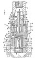
- FIG. 1 shows a flowmeter that incorporates this invention. It comprises a housing 10 having an inlet port 11 and an outlet port 12 at the ends of the housing 10 which, with other elements of the flowmeter, defines a generally annular passage for a fluid, such as aircraft fuel.
- the passage is generally disposed along a longitudinal axis 13.
- a first sensing coil assembly 14 generates first timing, or start, pulses and is affixed to the housing 10.
- the assembly 14 has a longitudinal axis that is perpendicular to the axis 13 and is secured in a shield 15.
- a second sensing coil assembly 16 generates second, or stop, timing pulses and is also affixed to the housing 10.
- the assembly 16 has a longitudinal axis that is coincident with the axis 13 and includes a sensing coil 17 that is located against a flange 20 at the outlet port 12. Conductors from both the first sensing coil assembly 14 and the second sensing coil assembly 16 terminate at a connector assembly (not shown). Both the coil assemblies 14 and 16 are isolated from the flow of fluid through the housing 10.
- a first inner, or turbine, assembly 22 is radially positioned in the housing 10 by the end flange 20 and is axially positioned by the end flange 20 and a retaining ring 21.
- the assembly 22 also supports a spring mechanism 23.
- a second, or rotor, inner assembly includes a flow straightener that comprises a plurality of longitudinally extending, circumferentially spaced vanes 25.
- the flow straightener is positioned in a tapered bore 26 and is mounted to one end of a stationary shaft 30A.
- An aligned rotatable shaft 30B is supported by the assembly 22 and lies on the longitudinal axis 13.
- a forward strut element in the rotor assembly comprises a stationary annulus 31. and a plurality of struts 32 that extend inwardly from the annulus 31 and that support a swirl generator 33.
- the annulus 31 radially positions the rotor assembly and coacts with a retaining ring to axially position the rotor assembly in the housing 10.
- the swirl generator 33 supports the shaft 30A.
- a flanged ring 34 is carried on the outer surface of the vanes 25 and supports one end of a variable diameter conduit 35 that includes a plurality of spring fingers that encircle the swirl generator 33.
- the conduit 35 acts as a flow responsive valve.
- a second ring 36 clamps the conduit 35 and the ring 34 to the vanes 25. This ring 36 also coacts with the housing 10 to radially position the shaft 30A.
- a rotor 37 is journalled on shaft 30A and is supported and positioned thereon by thrust bearings 41 and 42.
- a turbine 40 is axially spaced from rotor 37 and is secured to rotatable shaft 30B.
- Shaft 30B is journalled for rotation in assembly 22 by thrust bearings 43 and 44.
- a flat band, helical spring (not shown) in the spring mechanism 23 is clamped between the turbine shaft 30B and assembly 22 to restrain rotation of the turbine 40 about the axis 13.
- An outer annulus 45 on the rotor 37 supports a group of permanent bar magnets 46 in the periphery of the rotor 37.
- a start pulse is induced in the coil assembly 14 that indicates the passage of a predetermined point on the rotor 37 (i.e., the location of the magnets 46) past a predetermined point on the housing 10 (i.e., the location of the coil assembly 14).
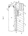
- another group of permanent bar magnets 47 also mounts to the outer annulus 45 of the rotor 37. More specifically, the annulus 45 has an annular extension 50 that extends toward and overlaps a portion of the turbine, specifically the ends of turbine blades 51 on the turbine. Grooves 52 are cut in the outer surface of the extension 50 to carry the bar magnets 47 which are closely spaced to each other.
- the turbine 40 in addition to the turbine blades 51, the turbine 40 carries an exciter blade 53 of a permeable material and a diametrically opposed, non-permeable, balancing blade 53A.
- An outer band, or shroud, 54 fits over the turbine blades 51, the exciter blade 53, and the balancing blade 53A.
- the band 54 engages a flux collecting ring 55 of a permeable material between the band 54 and a radial extension 56 on the turbine 40.
- the ring 55 bears against a tab 57 from the exciter blade 53 and a similar tab from the balancing blade.
- the extension 50 supports the magnets 47 so they rotate in a first circular path.
- An extension 61 from a main body 62 of the exciter blade axially overlaps the extension 50 and the magnets 47.
- the extension 61 moves in a second circular path that is concentric with the path of the extension 50, so the axially overlapped portions do not interfere during operation.
- the air gap 60 between the extension 50 below the magnets 47 and the extension 61 of the exciter blade 53 and another air gap 63 between the ring 54 and the housing 10 in the area of the coil 17 both comprise radial air gaps. There is no significant axial air gap. Because of the inherent stability in the length of radial air gaps, the length of the air gaps in the magnetic circuit is less sensitive to fluctuation as a result of mechanical vibrations and thermal expansion.
- the magnets 47 although within the coil 17, do not induce any significant voltage in the coil winding 17 as the rotation of the magnets 47 does not independently produce flux changes in the annular coil 17.
- the permeable flux collector ring 55 shown in FIGS. 1 and 4 improves the quality of the stop pulses from the coil 17.
- the magnetic circuit associated with the magnets 47 includes the exciter blade 53, the flux collector ring 55, and magnetic shields that are associated with the coil 17.
- the presence of the flux collector ring 55 in close association with the coil 17 about the entire periphery of the turbine 40 greatly reduces the reluctance of this flux path. As a result a greater percentage of the total flux from the magnets 47 couples the coil 17, so the quality of the stop pulses is improved.
- the voltage of the stop pulses even at low rotor speeds, is reliably detectable.
- the described magnetic flux collector ring 55 operates to reduce the reluctance of the magnetic circuit that couples flux to the sensing coil 17.
- Other flux collector ring arrangements could be mounted on the turbine and still provide the improved reluctance characteristics.
Landscapes
- Physics & Mathematics (AREA)
- Fluid Mechanics (AREA)
- General Physics & Mathematics (AREA)
- Measuring Volume Flow (AREA)
Applications Claiming Priority (2)
| Application Number | Priority Date | Filing Date | Title |
|---|---|---|---|
| US06/084,390 US4248100A (en) | 1979-10-12 | 1979-10-12 | Mass rate of flow meter with improved magnetic circuit |
| US84390 | 1987-08-11 |
Publications (3)
| Publication Number | Publication Date |
|---|---|
| EP0038839A1 EP0038839A1 (en) | 1981-11-04 |
| EP0038839A4 EP0038839A4 (en) | 1983-11-14 |
| EP0038839B1 true EP0038839B1 (en) | 1986-01-15 |
Family
ID=22184670
Family Applications (1)
| Application Number | Title | Priority Date | Filing Date |
|---|---|---|---|
| EP80902209A Expired EP0038839B1 (en) | 1979-10-12 | 1981-04-21 | Mass flowmeter |
Country Status (6)
| Country | Link |
|---|---|
| US (1) | US4248100A (cg-RX-API-DMAC7.html) |
| EP (1) | EP0038839B1 (cg-RX-API-DMAC7.html) |
| JP (1) | JPS6364730B2 (cg-RX-API-DMAC7.html) |
| DE (1) | DE3071354D1 (cg-RX-API-DMAC7.html) |
| IT (1) | IT1133843B (cg-RX-API-DMAC7.html) |
| WO (1) | WO1981001050A1 (cg-RX-API-DMAC7.html) |
Family Cites Families (3)
| Publication number | Priority date | Publication date | Assignee | Title |
|---|---|---|---|---|
| US3538767A (en) * | 1968-12-04 | 1970-11-10 | Gen Electric | Flowmeter fluid drive |
| FR2042520B1 (cg-RX-API-DMAC7.html) * | 1969-05-09 | 1974-05-24 | Elliott Bros | |
| US4056976A (en) * | 1976-10-12 | 1977-11-08 | General Electric Company | Mass rate of flow meter |
-
1979
- 1979-10-12 US US06/084,390 patent/US4248100A/en not_active Expired - Lifetime
-
1980
- 1980-10-09 IT IT25231/80A patent/IT1133843B/it active
- 1980-10-10 JP JP55502598A patent/JPS6364730B2/ja not_active Expired
- 1980-10-10 DE DE8080902209T patent/DE3071354D1/de not_active Expired
- 1980-10-10 WO PCT/US1980/001344 patent/WO1981001050A1/en not_active Ceased
-
1981
- 1981-04-21 EP EP80902209A patent/EP0038839B1/en not_active Expired
Also Published As
| Publication number | Publication date |
|---|---|
| JPS6364730B2 (cg-RX-API-DMAC7.html) | 1988-12-13 |
| WO1981001050A1 (en) | 1981-04-16 |
| EP0038839A4 (en) | 1983-11-14 |
| IT8025231A0 (it) | 1980-10-09 |
| DE3071354D1 (en) | 1986-02-27 |
| IT1133843B (it) | 1986-07-24 |
| JPS56501335A (cg-RX-API-DMAC7.html) | 1981-09-17 |
| EP0038839A1 (en) | 1981-11-04 |
| US4248100A (en) | 1981-02-03 |
Similar Documents
| Publication | Publication Date | Title |
|---|---|---|
| EP3396304B1 (en) | Feedback system for pitch-adjustable blades of aircraft bladed rotor | |
| US2683224A (en) | Flowmeter | |
| US4012957A (en) | Shrouded flowmeter turbine and improved fluid flowmeter using the same | |
| US2709366A (en) | Flow meter | |
| US4248099A (en) | Mass rate of flow meter with improved fluid drive | |
| US5370001A (en) | Angular momentum mass flowmeter | |
| US3538767A (en) | Flowmeter fluid drive | |
| EP0038839B1 (en) | Mass flowmeter | |
| EP0038352B1 (en) | Mass flowmeter | |
| EP0038351B1 (en) | Mass flowmeter | |
| EP0038840B1 (en) | Mass flowmeter | |
| US4314483A (en) | Mass rate of flow meter with improved temperature characteristics | |
| US3056292A (en) | Mass flowmeter | |
| GB958700A (en) | Improvements in or relating to flow meters | |
| JPS5815870Y2 (ja) | タ−ビンメ−タ | |
| GB893873A (en) | Improvements in and relating to flow meters | |
| JPH04256808A (ja) | タービン式流量計 |
Legal Events
| Date | Code | Title | Description |
|---|---|---|---|
| PUAI | Public reference made under article 153(3) epc to a published international application that has entered the european phase |
Free format text: ORIGINAL CODE: 0009012 |
|
| 17P | Request for examination filed |
Effective date: 19810807 |
|
| AK | Designated contracting states |
Designated state(s): DE FR GB |
|
| GRAA | (expected) grant |
Free format text: ORIGINAL CODE: 0009210 |
|
| AK | Designated contracting states |
Designated state(s): DE FR GB |
|
| REF | Corresponds to: |
Ref document number: 3071354 Country of ref document: DE Date of ref document: 19860227 |
|
| ET | Fr: translation filed | ||
| PLBE | No opposition filed within time limit |
Free format text: ORIGINAL CODE: 0009261 |
|
| STAA | Information on the status of an ep patent application or granted ep patent |
Free format text: STATUS: NO OPPOSITION FILED WITHIN TIME LIMIT |
|
| 26N | No opposition filed | ||
| REG | Reference to a national code |
Ref country code: GB Ref legal event code: 732 |
|
| REG | Reference to a national code |
Ref country code: FR Ref legal event code: TP Ref country code: FR Ref legal event code: CD |
|
| PGFP | Annual fee paid to national office [announced via postgrant information from national office to epo] |
Ref country code: GB Payment date: 19901005 Year of fee payment: 11 |
|
| PGFP | Annual fee paid to national office [announced via postgrant information from national office to epo] |
Ref country code: FR Payment date: 19901031 Year of fee payment: 11 |
|
| PGFP | Annual fee paid to national office [announced via postgrant information from national office to epo] |
Ref country code: DE Payment date: 19901128 Year of fee payment: 11 |
|
| PG25 | Lapsed in a contracting state [announced via postgrant information from national office to epo] |
Ref country code: GB Effective date: 19911010 |
|
| GBPC | Gb: european patent ceased through non-payment of renewal fee | ||
| PG25 | Lapsed in a contracting state [announced via postgrant information from national office to epo] |
Ref country code: FR Effective date: 19920630 |
|
| PG25 | Lapsed in a contracting state [announced via postgrant information from national office to epo] |
Ref country code: DE Effective date: 19920701 |
|
| REG | Reference to a national code |
Ref country code: FR Ref legal event code: ST |