EP0038035B1 - Light source comprising a high pressure discharge lamp - Google Patents
Light source comprising a high pressure discharge lamp Download PDFInfo
- Publication number
- EP0038035B1 EP0038035B1 EP81102713A EP81102713A EP0038035B1 EP 0038035 B1 EP0038035 B1 EP 0038035B1 EP 81102713 A EP81102713 A EP 81102713A EP 81102713 A EP81102713 A EP 81102713A EP 0038035 B1 EP0038035 B1 EP 0038035B1
- Authority
- EP
- European Patent Office
- Prior art keywords
- lamp
- discharge
- inductivity
- light source
- current
- Prior art date
- Legal status (The legal status is an assumption and is not a legal conclusion. Google has not performed a legal analysis and makes no representation as to the accuracy of the status listed.)
- Expired
Links
- 230000000737 periodic effect Effects 0.000 claims description 20
- 239000004020 conductor Substances 0.000 claims description 19
- 229910052756 noble gas Inorganic materials 0.000 claims description 12
- 230000001939 inductive effect Effects 0.000 claims description 7
- 239000000203 mixture Substances 0.000 claims description 4
- 230000001360 synchronised effect Effects 0.000 claims description 4
- 229910052724 xenon Inorganic materials 0.000 description 12
- FHNFHKCVQCLJFQ-UHFFFAOYSA-N xenon atom Chemical compound [Xe] FHNFHKCVQCLJFQ-UHFFFAOYSA-N 0.000 description 12
- DGAQECJNVWCQMB-PUAWFVPOSA-M Ilexoside XXIX Chemical compound C[C@@H]1CC[C@@]2(CC[C@@]3(C(=CC[C@H]4[C@]3(CC[C@@H]5[C@@]4(CC[C@@H](C5(C)C)OS(=O)(=O)[O-])C)C)[C@@H]2[C@]1(C)O)C)C(=O)O[C@H]6[C@@H]([C@H]([C@@H]([C@H](O6)CO)O)O)O.[Na+] DGAQECJNVWCQMB-PUAWFVPOSA-M 0.000 description 10
- 229910052708 sodium Inorganic materials 0.000 description 10
- 239000011734 sodium Substances 0.000 description 10
- 150000002835 noble gases Chemical class 0.000 description 7
- 238000000034 method Methods 0.000 description 4
- 230000000977 initiatory effect Effects 0.000 description 3
- 230000015572 biosynthetic process Effects 0.000 description 2
- 230000007423 decrease Effects 0.000 description 2
- 238000011161 development Methods 0.000 description 2
- 230000018109 developmental process Effects 0.000 description 2
- 238000010586 diagram Methods 0.000 description 2
- 230000005684 electric field Effects 0.000 description 2
- PNEYBMLMFCGWSK-UHFFFAOYSA-N aluminium oxide Inorganic materials [O-2].[O-2].[O-2].[Al+3].[Al+3] PNEYBMLMFCGWSK-UHFFFAOYSA-N 0.000 description 1
- 230000009286 beneficial effect Effects 0.000 description 1
- 229910010293 ceramic material Inorganic materials 0.000 description 1
- 238000010276 construction Methods 0.000 description 1
- 230000008878 coupling Effects 0.000 description 1
- 238000010168 coupling process Methods 0.000 description 1
- 238000005859 coupling reaction Methods 0.000 description 1
- 230000003247 decreasing effect Effects 0.000 description 1
- 230000000694 effects Effects 0.000 description 1
- 238000010891 electric arc Methods 0.000 description 1
- 239000007789 gas Substances 0.000 description 1
- 239000011521 glass Substances 0.000 description 1
- 238000010438 heat treatment Methods 0.000 description 1
- 239000000463 material Substances 0.000 description 1
- MJGFBOZCAJSGQW-UHFFFAOYSA-N mercury sodium Chemical compound [Na].[Hg] MJGFBOZCAJSGQW-UHFFFAOYSA-N 0.000 description 1
- 229910001023 sodium amalgam Inorganic materials 0.000 description 1
Images
Classifications
-
- H—ELECTRICITY
- H01—ELECTRIC ELEMENTS
- H01J—ELECTRIC DISCHARGE TUBES OR DISCHARGE LAMPS
- H01J61/00—Gas-discharge or vapour-discharge lamps
- H01J61/02—Details
- H01J61/54—Igniting arrangements, e.g. promoting ionisation for starting
- H01J61/541—Igniting arrangements, e.g. promoting ionisation for starting using a bimetal switch
- H01J61/544—Igniting arrangements, e.g. promoting ionisation for starting using a bimetal switch and an auxiliary electrode outside the vessel
-
- Y—GENERAL TAGGING OF NEW TECHNOLOGICAL DEVELOPMENTS; GENERAL TAGGING OF CROSS-SECTIONAL TECHNOLOGIES SPANNING OVER SEVERAL SECTIONS OF THE IPC; TECHNICAL SUBJECTS COVERED BY FORMER USPC CROSS-REFERENCE ART COLLECTIONS [XRACs] AND DIGESTS
- Y10—TECHNICAL SUBJECTS COVERED BY FORMER USPC
- Y10S—TECHNICAL SUBJECTS COVERED BY FORMER USPC CROSS-REFERENCE ART COLLECTIONS [XRACs] AND DIGESTS
- Y10S315/00—Electric lamp and discharge devices: systems
- Y10S315/01—Fluorescent lamp circuits with more than two principle electrodes
Definitions
- This invention relates to a light source, especially the starting of high intensity discharge lamps and, more particularly, to methods and apparatus for starting of discharge lamps containing noble gases at pressures in excess of 0,4 bar (300 Torr).
- High intensity discharge lamps such as high pressure sodium lamps commonly include noble gases at pressures below 0,133 bar (100 Torr). Lamps containing noble gases at pressures below 0,133 bar can be started and operated by utilizing an igniter in conjunction with a lamp ballast.
- the igniter provides high voltage, short duration pulses which assist in initiating discharge.
- the lamp ballast converts the ac line voltage to the proper amplitude and impedance level for lamp operation.
- a light source comprising, in combination:
- the light source can further include a light transmitting outer envelope surrounding the lamp, the conductor, and the pulsing means, and a lamp base for coupling power through the envelope to the lamp.
- said lamp inductivity includes an inductive output whereby the inductive output of the inductivity is operative, when the current drawn therefrom is rapidly reduced, to provide said high voltage pulse to said discharge lamp.
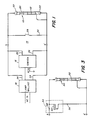
- a light source includes a high intensity discharge lamp 10, a conductor 12, a switching circuit 14, and can include an igniter 16 and a lamp inductivity 18.
- the discharge lamp 10 is a high pressure sodium lamp and includes a discharge tube 20, typically made of alumina or other transparent ceramic material, having electrodes 22 sealed therein at opposite ends.
- the conductor 12, typically a fine wire, is wrapped around the discharge tube 20 and is coupled to the electrode 22 which is connected to a reference potential such as ground.
- the lamp inductivity 18 receives ac power, typically 115 volts, 60 hertz, at its input and has its outputs 24 connected to the electrodes 22 of the discharge lamp 10.
- the igniter 16 receives an ac input from an auxiliary output of the lamp inductivity 18. Outputs 26 of the igniter 16 are coupled to the electrodes 22 of the discharge lamp 10.
- the switching circuit 14, as shown, includes a switch 28 and a resistor 30 coupled in series across the electrodes 22 of the discharge lamp 10. The resistor 30 provides current limiting and can be replaced by a short circuit without departing from the scope of the present invention.
- the discharge tube 20 encloses a fill material, typically including sodium or a sodium amalgam and a noble gas or mixture of noble gases. which emit light during discharge.
- a fill material typically including sodium or a sodium amalgam and a noble gas or mixture of noble gases.
- Lamp inductivities for high intensity discharge lamps are well known in the art and can be of the leading or lagging type.
- One example of a suitable lamp inductivity is General Electric Model No. 17G3202.
- the lamp inductivity 18 is operative to step the ac input voltage up or down depending on the magnitude of the ac input and to provide a relatively high impedance output.
- the igniter 16 also well known in the art, is operative to provide high amplitude, short duration pulses which assist in initiating discharge in the discharge lamp 10.
- Pulses appearing at outputs 26 are typically 2500 to 4000 volts in amplitude and at least one microsecond in duration. Furthermore, the pulses occur in timed relation to the ac power, typically being substantially synchronized with the peaks of the ac voltage.
- the specifications for the pulses produced by the igniter have been standardized by the American National Standards Institute in specification ANSI C78. 13501976.
- One example of a suitable igniter is General Electric Model No. 17G9932.
- the combination of the conductor 12, the switching circuit 14, and the igniter 16 form a starting circuit which is operative to initiate discharge in the discharge lamp 10 while the lamp inductivity 18 provides ac voltage and current on a continuous basis during starting and normal operation.
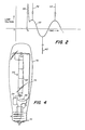
- the initiation of a discharge in the lamp 10 can be described as follows with reference to FIG. 2. Assume in the present example that the ac power is applied prior to the opening of the switch 28 and that the resistor 30 has a very small value. Thus, the lamp voltage remains approximately zero until time To when the switch 28 is opened. The opening of the switch 28 causes an inductively generated high voltage pulse 38 to be applied to the lamp.
- the lamp inductivity 18 provides at the outputs 24 and ac voltage 40, typically 180 volts ac for a 400 watt high pressure sodium lamp.
- the igniter 16 provides at its outputs 26 periodic pulses 42 having an amplitude of 2500 to 4000 volts and a duration of at least one microsecond.
- the periodic pulses 42 are substantially synchronized with the peaks of the ac voltage 40.
- Lead circuit inductivities require one pulse per half cycle of the ac voltage, as shown in FIG. 2, while lag circuit inductivities require one pulse per cycle of the ac voltage.
- the high voltage pulse 38 is generated when the switch 28 is opened.
- Typical lamp inductivities 18 include transformers and have highly inductive output impedances.
- a substantial current is drawn from the lamp inductivity 18 through the switch 28 and the resistor 30.
- the switch 28 is opened, the current drawn from the lamp inductivity 18 rapidly decreases and the inductive output of the lamp inductivity 18 generates the high voltage pulse 38.
- the energy provided by the high voltage pulse 38, in combination with the periodic pulses 42 and the conductor 12, is sufficient to form a discharge in the discharge lamp 10.
- the high voltage pulse 38 has an amplitude approximately equal to the amplitude of the periodic pulses 42 and a duration much greater than the duration of the periodic pulses 42.
- the high voltage pulse 38 is typically about 100 microseconds in duration.
- the effect of the conductor 12 around the discharge tube 20 is to provide electric field distortion such that the electric field near the electrode 22 is intensified within the discharge tube.
- the development of ionization in this region is thought to spread progressively along the inside surface of the discharge tube 20 until a continuous path of ionization is produced between the two electrodes 22.
- the path is relatively highly conductive.
- the ionization path absorbs additional power and increases in conductivity until an arc discharge is formed and the lamp has been started.
- the initial ionization path does not absorb additional power and arc formation does not occur in the absence of the switching circuit 14.
- the voltage levels in the inductivity system must not exceed the rated values, typically about 2500 volts for standard high pressure sodium lamp inductivities.
- the amplitude of the high pulse 38 is given by L di/dt where L is the output inductance of the lamp inductivity, di is the change in current when the switch 28 is opened, and dt is the time required for di to occur.
- the amplitude of the pulse can be controlled either by controlling the current through the switch 28 or by controlling the speed at which the switch 28 opens. It is possible to limit the current through the switch 28 by the series resistance 30. Effective starting can be achieved when series resistance values of 100 ohms or more are utilized.
- the circuit shown in FIG. 1 is but one way of generating the high voltage pulse 38. Any suitable high voltage pulse generating circuit can be utilized. Furthermore, the duration of the high voltage pulse 38 applied to the lamp 10 is not critical provided the pulse has a duration which is long in relation to the periodic pulses 42. It is to be understood that, while the configuration shown in FIG. 1 is most useful to start and operate high intensity lamps containing noble gases at pressures in excess of 0,4 bar, it can also be used to start and operate lamps containing noble gases at lower pressure.
- the light source includes a discharge lamp 50, a conductor 52, a thermal switch 54, and a current limiting resistor 56, which are to be used in conjunction with a lamp inductivity and an igniter.
- the lamp circuit shown in FIG. 3 can replace the lamp 10, the conductor 12, and the switching circuit 14 in FIG. 1 by connecting the points labelled A and A' in FIG. 3 to the points A and A', respectively, in FIG. 1.
- the discharge lamp 50 shown in FIG. 3 corresponds to the discharge lamp 10 shown in FIG. 1 and is a high pressure sodium lamp including xenon or other noble gases at pressures in excess of 0,4 N/cm 2.
- the conductor 52 is typically a fine wire and is wrapped around the discharge tube and is connected to one electrode of the discharge lamp 50.
- the thermal switch 54 includes a heater resistor 58 and a bimetal switch 60 connected in series. The inputs A and A' from the lamp inductivity and the igniter are coupled through the heater resistor 58 to the electrodes of the discharge lamp 50.
- the bimetal switch 60 and the current limiting resistor 56 are coupled in series across the electrodes of the discharge lamp 50.
- the lamp inductivity provides ac voltage and current to the points A and A' and the igniter provides periodic pulses of high amplitude and short duration to the points A and A' as described hereinabove.
- the conductor 52 promotes the formation of an ionization path within the discharge lamp 50 as described hereinabove.
- the bimetal switch 60 is closed. Therefore, when power is applied to the points A and A', current flows through the resistor 58, the bimetal switch 60, and the resistor 56.
- the heater resistor 58 is placed in close proximity to the bimetal switch so that heat generated by current passing therethrough will heat the bimetal switch 60.
- the heat generated by the resistor 58 causes the bimetal switch 60 to switch to the open position and the current drawn from the inductivity is rapidly decreased.
- the rapid decrease in current drawn from the inductivity causes the highly inductive output of the inductivity to generate a high voltage pulse which provides sufficient energy to initiate discharge in the lamp 50 as hereinabove described and shown in FIG. 2.
- the current drawn by the discharge lamp 50 through the resistor 58 causes the resistor 58 to remain heated and the bimetal switch 60 to remain in the open position. If for some reason, the discharge lamp 50 does not start when the bimetal switch 60 opens, no current is drawn through the resistor 58 and the bimetal switch 60 cools until it recloses. Heating of the resistor 58 again occurs, causing the bimetal switch 60 to open and another high voltage starting pulse is granted. Thus, the starting process is repeated until a discharge is initiated in the lamp 50.
- FIG. 4 depicts a configuration of the light source shown in FIG. 3 which facilitates replacement of standard high pressure sodium lamps with lamps containing xenon at pressures in excess of 0,4 bar.
- high pressure sodium lamps having the improved performance characteristics provided by high pressure xenon can be operated directly from existing lamp inductivities (ballasts) and igniters.
- the discharge lamp 50, the conductor 52, the thermal switch 54, and the current limiting resistor 56 are mounted within a light transmitting outer envelope 70 which can be glass.
- the elements are connected electrically as shown in FIG. 3 and described hereinabove.
- AC power and periodic pulses are received by a standard lamp socket 72 and are coupled through a lamp stem 74 to the lamp circuit shown in FIG. 3.
- the outer envelope 70 can have any convenient shape.
- the discharge lamp 50 is supported within the outer envelope 70 by a rigid frame 76.
- the construction of the outer envelope 70, the lamp base 72, and the frame 76 are well known in the art.
- the conductor 52 is wrapped around the discharge lamp 50 and is coupled to one of the electrodes of the discharge lamp 50. A fine wire is used to minimize light blockage.
- the thermal switch 54 and the current limiting resistor 56 are preferably located below the discharge lamp 50 in order to minimize light blockage by these elements.
Landscapes
- Discharge Lamps And Accessories Thereof (AREA)
- Circuit Arrangements For Discharge Lamps (AREA)
Description
- This invention relates to a light source, especially the starting of high intensity discharge lamps and, more particularly, to methods and apparatus for starting of discharge lamps containing noble gases at pressures in excess of 0,4 bar (300 Torr).
- High intensity discharge lamps such as high pressure sodium lamps commonly include noble gases at pressures below 0,133 bar (100 Torr). Lamps containing noble gases at pressures below 0,133 bar can be started and operated by utilizing an igniter in conjunction with a lamp ballast. The igniter provides high voltage, short duration pulses which assist in initiating discharge. The lamp ballast converts the ac line voltage to the proper amplitude and impedance level for lamp operation.
- It has been found, that the inclusion in high pressure sodium lamps of xenon as the noble gas at pressures well in excess of 0,133 bar is beneficial to lamp performance. However, the igniter described above does not produce reliable starting at xenon pressures about 0,133 bar. From US-A-4,179,640 it is known that a high voltage pulse in cooperation with a conductor in close proximity to the surface of the discharge tube will be suited to start lamps having xenon full pressure up to 0,4 bar, provided the conductor extends the entire distance between the two electrodes of the discharge tube. Accordingly, it cannot be expected that at lighter xenon pressures this starting means can be used.
- Another arrangement for starting high pressure discharge lamps is shown in U.S. Patent No. 4,137,483, issued January 30,1979, to Ochi et al. A switching circuit contained within the lamp induces a high voltage starting pulse. The high voltage pulse operates in conjunction with a conductor wrapped around the discharge tube to initiate discharge in the lamp. The igniter and the conventional ballast are not used.
- As follows from the GB-PS-1342026 it is known, to start a gas discharge lamp with a ballast. This GB-PS deals especially with the starting of low pressure (fluorescent) lamps. Those lamps are started according to this known prior art by synchronization of short duration periodic pulses with peaks of an AC power. For starting high pressure discharge lamps, this known device is not used.
- Recent developments have indicated the desirability of including xenon at pressures in excess of 0,4 bar in high pressure sodium lamps. However, none of the starting arrangements described above are effective to reliably start lamps having xenon pressures in excess of 0,4 bar.
- It is a general object of the present invention to provide new and improved methods and apparatus for starting of high intensity discharge lamps.
- It is another object of the present invention to provide methods and apparatus for starting of high intensity discharge lamps containing a noble gas or mixtures thereof at pressures in excess of 0,4 bar.
- According to the present invention, these and other objects and advantages are achieved in a light source comprising, in combination:
- A high pressure discharge lamp including a discharge tube having electrodes sealed therein at opposite ends and enclosing a noble gas or mixtures thereof having a pressure of greater than 0,4 bar (300 Torr), and a conductor coupled to one of said electrodes and located in close proximity to an outer surface of said discharge tube; a lamp inductance which provides ac voltage and current and an igniter which provides periodic pulses having an amplitude of 2500 to 4000 volts and a duration of at least one microsecond, said periodic pulses being substantially synchronized with the peaks of the ac voltage, and a switching circuit including switching means having an input for receiving current from the inductivity for drawing a current from the inductance in one switching state and for rapidly reducing the current drawn from the inductivity in an opposite switching state and having outputs coupled to said electrodes, for generating at said outputs a high voltage pulse having an amplitude about that of said periodic pulses, and a duration much greater than that of said periodic pulses whereby, upon application of ac power to said light source, said periodic pulses, said conductor and said high voltage pulse co-operate to initiate a discharge in said lamp.
- The light source can further include a light transmitting outer envelope surrounding the lamp, the conductor, and the pulsing means, and a lamp base for coupling power through the envelope to the lamp.
- It is advantageous when said lamp inductivity includes an inductive output whereby the inductive output of the inductivity is operative, when the current drawn therefrom is rapidly reduced, to provide said high voltage pulse to said discharge lamp.
- In the drawings:
- FIG. 1 is a schematic block diagram of a light source according to the present invention;
- FIG. 2 is a graphic illustration of the voltage wave form applied to the electrodes of the discharge lamp shown in FIG. 1;
- FIG. 3 is a schematic diagram of a preferred embodiment of a light source according to the present invention; and
- FIG. 4 is an illustration of the physical configuration of the light source shown in FIG. 3.
- For a better understanding of the present invention, together with other and further objects, advantages, and capabilities thereof, reference is made to the following disclosure and appended claims in connection with the above-described drawings.
- Referring now to FIG. 1, a light source according to the present invention includes a high
intensity discharge lamp 10, aconductor 12, aswitching circuit 14, and can include anigniter 16 and alamp inductivity 18. Thedischarge lamp 10 is a high pressure sodium lamp and includes adischarge tube 20, typically made of alumina or other transparent ceramic material, havingelectrodes 22 sealed therein at opposite ends. Theconductor 12, typically a fine wire, is wrapped around thedischarge tube 20 and is coupled to theelectrode 22 which is connected to a reference potential such as ground. Thelamp inductivity 18 receives ac power, typically 115 volts, 60 hertz, at its input and has itsoutputs 24 connected to theelectrodes 22 of thedischarge lamp 10. Theigniter 16 receives an ac input from an auxiliary output of thelamp inductivity 18.Outputs 26 of theigniter 16 are coupled to theelectrodes 22 of thedischarge lamp 10. Theswitching circuit 14, as shown, includes aswitch 28 and aresistor 30 coupled in series across theelectrodes 22 of thedischarge lamp 10. Theresistor 30 provides current limiting and can be replaced by a short circuit without departing from the scope of the present invention. - The
discharge tube 20 encloses a fill material, typically including sodium or a sodium amalgam and a noble gas or mixture of noble gases. which emit light during discharge. In particular, the inclusion in thedischarge tube 20 of xenon at pressures above 0,4 bar provides superior lamp performance. Lamp inductivities for high intensity discharge lamps are well known in the art and can be of the leading or lagging type. One example of a suitable lamp inductivity is General Electric Model No. 17G3202. Thelamp inductivity 18 is operative to step the ac input voltage up or down depending on the magnitude of the ac input and to provide a relatively high impedance output. Theigniter 16, also well known in the art, is operative to provide high amplitude, short duration pulses which assist in initiating discharge in thedischarge lamp 10. Pulses appearing atoutputs 26 are typically 2500 to 4000 volts in amplitude and at least one microsecond in duration. Furthermore, the pulses occur in timed relation to the ac power, typically being substantially synchronized with the peaks of the ac voltage. The specifications for the pulses produced by the igniter have been standardized by the American National Standards Institute in specification ANSI C78. 13501976. One example of a suitable igniter is General Electric Model No. 17G9932. - The combination of the
conductor 12, theswitching circuit 14, and theigniter 16 form a starting circuit which is operative to initiate discharge in thedischarge lamp 10 while thelamp inductivity 18 provides ac voltage and current on a continuous basis during starting and normal operation. The initiation of a discharge in thelamp 10 can be described as follows with reference to FIG. 2. Assume in the present example that the ac power is applied prior to the opening of theswitch 28 and that theresistor 30 has a very small value. Thus, the lamp voltage remains approximately zero until time To when theswitch 28 is opened. The opening of theswitch 28 causes an inductively generated high voltage pulse 38 to be applied to the lamp. After the opening of theswitch 28, thelamp inductivity 18 provides at theoutputs 24 andac voltage 40, typically 180 volts ac for a 400 watt high pressure sodium lamp. At the same time, theigniter 16 provides at itsoutputs 26periodic pulses 42 having an amplitude of 2500 to 4000 volts and a duration of at least one microsecond. Theperiodic pulses 42 are substantially synchronized with the peaks of theac voltage 40. Lead circuit inductivities require one pulse per half cycle of the ac voltage, as shown in FIG. 2, while lag circuit inductivities require one pulse per cycle of the ac voltage. After the discharge is established and thelamp 10 is fully warmed up, the current drawn by thelamp 10 reduces theac output voltage 40 of thelamp inductivity 18 andperiodic pulses 42 are no longer provided. - As noted above, the high voltage pulse 38 is generated when the
switch 28 is opened.Typical lamp inductivities 18 include transformers and have highly inductive output impedances. Prior to the time To, a substantial current is drawn from thelamp inductivity 18 through theswitch 28 and theresistor 30. When theswitch 28 is opened, the current drawn from thelamp inductivity 18 rapidly decreases and the inductive output of thelamp inductivity 18 generates the high voltage pulse 38. The energy provided by the high voltage pulse 38, in combination with theperiodic pulses 42 and theconductor 12, is sufficient to form a discharge in thedischarge lamp 10. For optimum lamp starting, the high voltage pulse 38 has an amplitude approximately equal to the amplitude of theperiodic pulses 42 and a duration much greater than the duration of theperiodic pulses 42. The high voltage pulse 38 is typically about 100 microseconds in duration. - The effect of the
conductor 12 around thedischarge tube 20 is to provide electric field distortion such that the electric field near theelectrode 22 is intensified within the discharge tube. The development of ionization in this region is thought to spread progressively along the inside surface of thedischarge tube 20 until a continuous path of ionization is produced between the twoelectrodes 22. When an ionization path is formed in which electron densities and temperatures are sufficiently elevated, the path is relatively highly conductive. At xenon pressures below 0,4 bar, the ionization path absorbs additional power and increases in conductivity until an arc discharge is formed and the lamp has been started. However, at xenon pressures in excess of 0,4 bar, the initial ionization path does not absorb additional power and arc formation does not occur in the absence of the switchingcircuit 14. - The voltage levels in the inductivity system must not exceed the rated values, typically about 2500 volts for standard high pressure sodium lamp inductivities. The amplitude of the high pulse 38 is given by L di/dt where L is the output inductance of the lamp inductivity, di is the change in current when the
switch 28 is opened, and dt is the time required for di to occur. Thus, the amplitude of the pulse can be controlled either by controlling the current through theswitch 28 or by controlling the speed at which theswitch 28 opens. It is possible to limit the current through theswitch 28 by theseries resistance 30. Effective starting can be achieved when series resistance values of 100 ohms or more are utilized. - It will be obvious to those skilled in the art that the circuit shown in FIG. 1 is but one way of generating the high voltage pulse 38. Any suitable high voltage pulse generating circuit can be utilized. Furthermore, the duration of the high voltage pulse 38 applied to the
lamp 10 is not critical provided the pulse has a duration which is long in relation to theperiodic pulses 42. It is to be understood that, while the configuration shown in FIG. 1 is most useful to start and operate high intensity lamps containing noble gases at pressures in excess of 0,4 bar, it can also be used to start and operate lamps containing noble gases at lower pressure. - Referring now to FIGS. 3 and 4, there is shown a light source according to the present invention which provides automatic starting. The light source includes a
discharge lamp 50, aconductor 52, athermal switch 54, and a current limitingresistor 56, which are to be used in conjunction with a lamp inductivity and an igniter. The lamp circuit shown in FIG. 3 can replace thelamp 10, theconductor 12, and the switchingcircuit 14 in FIG. 1 by connecting the points labelled A and A' in FIG. 3 to the points A and A', respectively, in FIG. 1. Thedischarge lamp 50 shown in FIG. 3 corresponds to thedischarge lamp 10 shown in FIG. 1 and is a high pressure sodium lamp including xenon or other noble gases at pressures in excess of 0,4 N/cm2. Theconductor 52 is typically a fine wire and is wrapped around the discharge tube and is connected to one electrode of thedischarge lamp 50. Thethermal switch 54 includes aheater resistor 58 and abimetal switch 60 connected in series. The inputs A and A' from the lamp inductivity and the igniter are coupled through theheater resistor 58 to the electrodes of thedischarge lamp 50. Thebimetal switch 60 and the current limitingresistor 56 are coupled in series across the electrodes of thedischarge lamp 50. - In operation, the lamp inductivity provides ac voltage and current to the points A and A' and the igniter provides periodic pulses of high amplitude and short duration to the points A and A' as described hereinabove. Also, the
conductor 52 promotes the formation of an ionization path within thedischarge lamp 50 as described hereinabove. In a cold condition, thebimetal switch 60 is closed. Therefore, when power is applied to the points A and A', current flows through theresistor 58, thebimetal switch 60, and theresistor 56. Theheater resistor 58 is placed in close proximity to the bimetal switch so that heat generated by current passing therethrough will heat thebimetal switch 60. After a predetermined time, the heat generated by theresistor 58 causes thebimetal switch 60 to switch to the open position and the current drawn from the inductivity is rapidly decreased. The rapid decrease in current drawn from the inductivity causes the highly inductive output of the inductivity to generate a high voltage pulse which provides sufficient energy to initiate discharge in thelamp 50 as hereinabove described and shown in FIG. 2. The current drawn by thedischarge lamp 50 through theresistor 58 causes theresistor 58 to remain heated and thebimetal switch 60 to remain in the open position. If for some reason, thedischarge lamp 50 does not start when thebimetal switch 60 opens, no current is drawn through theresistor 58 and thebimetal switch 60 cools until it recloses. Heating of theresistor 58 again occurs, causing thebimetal switch 60 to open and another high voltage starting pulse is granted. Thus, the starting process is repeated until a discharge is initiated in thelamp 50. - FIG. 4 depicts a configuration of the light source shown in FIG. 3 which facilitates replacement of standard high pressure sodium lamps with lamps containing xenon at pressures in excess of 0,4 bar. Thus, high pressure sodium lamps having the improved performance characteristics provided by high pressure xenon can be operated directly from existing lamp inductivities (ballasts) and igniters. The
discharge lamp 50, theconductor 52, thethermal switch 54, and the current limitingresistor 56 are mounted within a light transmittingouter envelope 70 which can be glass. The elements are connected electrically as shown in FIG. 3 and described hereinabove. AC power and periodic pulses are received by astandard lamp socket 72 and are coupled through alamp stem 74 to the lamp circuit shown in FIG. 3. Theouter envelope 70 can have any convenient shape. Thedischarge lamp 50 is supported within theouter envelope 70 by arigid frame 76. The construction of theouter envelope 70, thelamp base 72, and theframe 76 are well known in the art. Theconductor 52 is wrapped around thedischarge lamp 50 and is coupled to one of the electrodes of thedischarge lamp 50. A fine wire is used to minimize light blockage. Thethermal switch 54 and the current limitingresistor 56 are preferably located below thedischarge lamp 50 in order to minimize light blockage by these elements.
Claims (2)
Applications Claiming Priority (2)
| Application Number | Priority Date | Filing Date | Title |
|---|---|---|---|
| US06/139,310 US4328446A (en) | 1980-04-11 | 1980-04-11 | Method and apparatus for starting high intensity discharge lamps |
| US139310 | 1980-04-11 |
Publications (2)
| Publication Number | Publication Date |
|---|---|
| EP0038035A1 EP0038035A1 (en) | 1981-10-21 |
| EP0038035B1 true EP0038035B1 (en) | 1985-11-13 |
Family
ID=22486040
Family Applications (1)
| Application Number | Title | Priority Date | Filing Date |
|---|---|---|---|
| EP81102713A Expired EP0038035B1 (en) | 1980-04-11 | 1981-04-09 | Light source comprising a high pressure discharge lamp |
Country Status (5)
| Country | Link |
|---|---|
| US (1) | US4328446A (en) |
| EP (1) | EP0038035B1 (en) |
| JP (1) | JPS56165258A (en) |
| CA (1) | CA1162594A (en) |
| DE (1) | DE3172871D1 (en) |
Families Citing this family (19)
| Publication number | Priority date | Publication date | Assignee | Title |
|---|---|---|---|---|
| US4355265A (en) * | 1980-12-15 | 1982-10-19 | Gte Products Corporation | Discharge lamp starting and operating circuit |
| US4329621A (en) * | 1980-12-15 | 1982-05-11 | Gte Products Corporation | Starter and discharge lamp starting circuit |
| NL8006802A (en) * | 1980-12-16 | 1982-07-16 | Philips Nv | STARTER FOR IGNITION OF A GAS AND / OR VAPOR DISCHARGE TUBE, AND ELECTRICAL DEVICE AND LAMP EQUIPPED WITH SUCH A STARTER. |
| US4721888A (en) * | 1984-12-27 | 1988-01-26 | Gte Laboratories Incorporated | Arc discharge lamp with ultraviolet enhanced starting circuit |
| US4629945A (en) * | 1984-12-27 | 1986-12-16 | Gte Laboratories Incorporated | Method and apparatus for starting low wattage high intensity discharge lamps |
| US4608521A (en) * | 1984-12-27 | 1986-08-26 | Gte Laboratories Incorporated | Dual spiral line generator method and apparatus for starting low wattage high intensity discharge lamps |
| EP0222824A1 (en) * | 1985-04-26 | 1987-05-27 | HERRICk, Kennan Clark | Apparatus and method for forming segmented luminosity in gas discharge tubes |
| US4812714A (en) * | 1987-10-22 | 1989-03-14 | Gte Products Corporation | Arc discharge lamp with electrodeless ultraviolet radiation starting source |
| US4818915A (en) * | 1987-10-22 | 1989-04-04 | Gte Products Corporation | Arc discharge lamp with ultraviolet radiation starting source |
| GB2220076A (en) * | 1988-06-21 | 1989-12-28 | English Electric Valve Co Ltd | Thyratron test circuit |
| CA2206200C (en) * | 1997-04-18 | 2000-06-27 | Matsushita Electric Works, Ltd. | Discharge lamp lighting device |
| US6054816A (en) * | 1997-06-02 | 2000-04-25 | High End Systems, Inc. | Active snubbing in a discharge lamp ballast |
| US5945786A (en) * | 1997-06-02 | 1999-08-31 | High End Systems, Inc. | Discharge lamp igniter with reduced noise output |
| US6297583B1 (en) | 1998-10-08 | 2001-10-02 | Federal-Mogul World Wide, Inc. | Gas discharge lamp assembly with improved r.f. shielding |
| JP2002190281A (en) * | 2000-12-22 | 2002-07-05 | Matsushita Electric Ind Co Ltd | High pressure discharge lamp |
| JP3528836B2 (en) * | 2002-01-09 | 2004-05-24 | ウシオ電機株式会社 | Discharge lamp |
| CN1636424A (en) * | 2002-02-19 | 2005-07-06 | 通达商业集团国际公司 | Starter assemblies for gas discharge lamps |
| DE60320389T2 (en) * | 2002-03-13 | 2009-05-14 | Koninklijke Philips Electronics N.V. | ELECTRICAL CIRCUIT FOR IGNITION OF A DISCHARGE LAMP, COMPONENT MODULE AND LAMP WITH SUCH ELECTRICAL CIRCUIT |
| GB2477463B (en) * | 2011-05-17 | 2013-01-16 | Greentek Green Solutions 2009 Ltd | System and method for ignition and operation of a high-intensity discharge lamp |
Family Cites Families (12)
| Publication number | Priority date | Publication date | Assignee | Title |
|---|---|---|---|---|
| AT308905B (en) * | 1970-04-09 | 1973-07-25 | Ernst Voegeli | Ballast for heated gas discharge tubes |
| US3721846A (en) * | 1972-06-26 | 1973-03-20 | Gte Sylvania Inc | Sodium vapor lamp having improved starting means including a heater |
| US3806748A (en) * | 1973-03-08 | 1974-04-23 | Gte Sylvania Inc | Sodium vapor lamp having a grooved alumina arc tube with side rod heater retainer |
| DE2517818A1 (en) * | 1975-04-22 | 1976-11-04 | Patra Patent Treuhand | IGNITION AND OPERATING DEVICE FOR A HIGH PRESSURE DISCHARGE LAMP |
| GB1496918A (en) * | 1975-08-14 | 1978-01-05 | Cates J | Low pressure discharge lamp starting and operating circui |
| US4001634A (en) * | 1975-09-02 | 1977-01-04 | General Electric Company | Discharge lamp having thermal switch starter |
| JPS5267174A (en) * | 1975-12-02 | 1977-06-03 | Iwasaki Electric Co Ltd | High voltage discharge lamp containing starter circuit |
| NL183973B (en) * | 1976-05-05 | 1988-10-03 | Philips Nv | METAL VAPOR DISCHARGE LAMP. |
| JPS5316475A (en) * | 1976-07-30 | 1978-02-15 | Hitachi Ltd | Discharge lamp starter |
| US4179640A (en) * | 1977-12-05 | 1979-12-18 | Westinghouse Electric Corp. | Hid sodium lamp which incorporates a high pressure of xenon and a trigger starting electrode |
| NL7809055A (en) * | 1978-09-05 | 1980-03-07 | Philips Nv | GAS AND / OR VAPOR DISCHARGE LAMP. |
| US4258288A (en) * | 1979-05-09 | 1981-03-24 | Westinghouse Electric Corp. | Resistor-aided starting of metal halide lamps |
-
1980
- 1980-04-11 US US06/139,310 patent/US4328446A/en not_active Expired - Lifetime
-
1981
- 1981-04-06 CA CA000374784A patent/CA1162594A/en not_active Expired
- 1981-04-09 DE DE8181102713T patent/DE3172871D1/en not_active Expired
- 1981-04-09 EP EP81102713A patent/EP0038035B1/en not_active Expired
- 1981-04-10 JP JP5309681A patent/JPS56165258A/en active Pending
Also Published As
| Publication number | Publication date |
|---|---|
| CA1162594A (en) | 1984-02-21 |
| JPS56165258A (en) | 1981-12-18 |
| US4328446A (en) | 1982-05-04 |
| EP0038035A1 (en) | 1981-10-21 |
| DE3172871D1 (en) | 1985-12-19 |
Similar Documents
| Publication | Publication Date | Title |
|---|---|---|
| US4328446A (en) | Method and apparatus for starting high intensity discharge lamps | |
| US4281274A (en) | Discharge lamp having vitreous shield | |
| US4179640A (en) | Hid sodium lamp which incorporates a high pressure of xenon and a trigger starting electrode | |
| US4135114A (en) | Starting device for discharge lamp | |
| US3746914A (en) | Arc discharge tube with surrounding starting coil | |
| US6034477A (en) | High-pressure discharge lamp | |
| US4170744A (en) | Combination discharge-incandescent lamp with thermal switch control | |
| US3721846A (en) | Sodium vapor lamp having improved starting means including a heater | |
| US4355261A (en) | Discharge lamp with integral starter | |
| US4513227A (en) | High intensity discharge (HID) lamp starting apparatus | |
| US3900761A (en) | High intensity metal arc discharge lamp | |
| US3828214A (en) | Plasma enshrouded electric discharge device | |
| EP0168087B1 (en) | High-pressure sodium discharge lamp | |
| EP0054271B1 (en) | Discharge lamp starting and operating circuit | |
| US3757159A (en) | Sodium vapor lamp having improved starting means | |
| EP0054270B1 (en) | Starter and discharge lamp starting circuit | |
| US4808888A (en) | Starting circuit for gaseous discharge lamps | |
| US3721845A (en) | Sodium vapor lamp having improved starting means | |
| US4779026A (en) | Rapid-start high-pressure discharge lamp, and method of its operation | |
| US4465954A (en) | Discharge lamp starting and operating circuit | |
| US3755708A (en) | Sodium vapor lamps having improved starting means | |
| EP0517304A2 (en) | High-pressure gas discharge lamp | |
| US7132800B2 (en) | High-pressure discharge lamp | |
| US5051649A (en) | Arc discharge lamp with liquid metal and heating means | |
| RU2018185C1 (en) | Gaseous-discharge lamp |
Legal Events
| Date | Code | Title | Description |
|---|---|---|---|
| PUAI | Public reference made under article 153(3) epc to a published international application that has entered the european phase |
Free format text: ORIGINAL CODE: 0009012 |
|
| 17P | Request for examination filed |
Effective date: 19810409 |
|
| AK | Designated contracting states |
Designated state(s): BE DE FR GB IT NL |
|
| ITF | It: translation for a ep patent filed | ||
| GRAA | (expected) grant |
Free format text: ORIGINAL CODE: 0009210 |
|
| AK | Designated contracting states |
Designated state(s): BE DE FR GB IT NL |
|
| REF | Corresponds to: |
Ref document number: 3172871 Country of ref document: DE Date of ref document: 19851219 |
|
| ET | Fr: translation filed | ||
| PLBE | No opposition filed within time limit |
Free format text: ORIGINAL CODE: 0009261 |
|
| STAA | Information on the status of an ep patent application or granted ep patent |
Free format text: STATUS: NO OPPOSITION FILED WITHIN TIME LIMIT |
|
| 26N | No opposition filed | ||
| PGFP | Annual fee paid to national office [announced via postgrant information from national office to epo] |
Ref country code: NL Payment date: 19870430 Year of fee payment: 7 |
|
| PG25 | Lapsed in a contracting state [announced via postgrant information from national office to epo] |
Ref country code: GB Effective date: 19890409 |
|
| PG25 | Lapsed in a contracting state [announced via postgrant information from national office to epo] |
Ref country code: BE Effective date: 19890430 |
|
| BERE | Be: lapsed |
Owner name: GTE LABORATORIES INC. Effective date: 19890430 |
|
| PG25 | Lapsed in a contracting state [announced via postgrant information from national office to epo] |
Ref country code: NL Effective date: 19891101 |
|
| GBPC | Gb: european patent ceased through non-payment of renewal fee | ||
| NLV4 | Nl: lapsed or anulled due to non-payment of the annual fee | ||
| PG25 | Lapsed in a contracting state [announced via postgrant information from national office to epo] |
Ref country code: FR Free format text: LAPSE BECAUSE OF NON-PAYMENT OF DUE FEES Effective date: 19891228 |
|
| PG25 | Lapsed in a contracting state [announced via postgrant information from national office to epo] |
Ref country code: DE Effective date: 19900103 |
|
| REG | Reference to a national code |
Ref country code: FR Ref legal event code: ST |