EP0037772B1 - Séparateur thermique à distributeur mobile - Google Patents
Séparateur thermique à distributeur mobile Download PDFInfo
- Publication number
- EP0037772B1 EP0037772B1 EP81400502A EP81400502A EP0037772B1 EP 0037772 B1 EP0037772 B1 EP 0037772B1 EP 81400502 A EP81400502 A EP 81400502A EP 81400502 A EP81400502 A EP 81400502A EP 0037772 B1 EP0037772 B1 EP 0037772B1
- Authority
- EP
- European Patent Office
- Prior art keywords
- distributor
- gas
- thermal separator
- separator according
- pulsatory
- Prior art date
- Legal status (The legal status is an assumption and is not a legal conclusion. Google has not performed a legal analysis and makes no representation as to the accuracy of the status listed.)
- Expired
Links
- 239000007787 solid Substances 0.000 claims description 5
- 230000003042 antagnostic effect Effects 0.000 claims 1
- 230000000087 stabilizing effect Effects 0.000 claims 1
- 230000001131 transforming effect Effects 0.000 claims 1
- 239000007789 gas Substances 0.000 description 33
- 238000005192 partition Methods 0.000 description 6
- 210000002381 plasma Anatomy 0.000 description 6
- 208000031968 Cadaver Diseases 0.000 description 5
- 230000002093 peripheral effect Effects 0.000 description 5
- OAKJQQAXSVQMHS-UHFFFAOYSA-N Hydrazine Chemical compound NN OAKJQQAXSVQMHS-UHFFFAOYSA-N 0.000 description 4
- 238000002347 injection Methods 0.000 description 4
- 239000007924 injection Substances 0.000 description 4
- OKKJLVBELUTLKV-UHFFFAOYSA-N Methanol Chemical compound OC OKKJLVBELUTLKV-UHFFFAOYSA-N 0.000 description 3
- 238000004891 communication Methods 0.000 description 3
- 238000011049 filling Methods 0.000 description 3
- 239000012530 fluid Substances 0.000 description 3
- HSFWRNGVRCDJHI-UHFFFAOYSA-N Acetylene Chemical compound C#C HSFWRNGVRCDJHI-UHFFFAOYSA-N 0.000 description 2
- QGZKDVFQNNGYKY-UHFFFAOYSA-N Ammonia Chemical compound N QGZKDVFQNNGYKY-UHFFFAOYSA-N 0.000 description 2
- 238000005299 abrasion Methods 0.000 description 2
- 230000008901 benefit Effects 0.000 description 2
- 239000012159 carrier gas Substances 0.000 description 2
- 238000010586 diagram Methods 0.000 description 2
- 235000021183 entrée Nutrition 0.000 description 2
- 238000010438 heat treatment Methods 0.000 description 2
- 239000001257 hydrogen Substances 0.000 description 2
- 229910052739 hydrogen Inorganic materials 0.000 description 2
- JMANVNJQNLATNU-UHFFFAOYSA-N oxalonitrile Chemical compound N#CC#N JMANVNJQNLATNU-UHFFFAOYSA-N 0.000 description 2
- 238000007254 oxidation reaction Methods 0.000 description 2
- 230000004224 protection Effects 0.000 description 2
- 238000010926 purge Methods 0.000 description 2
- 238000000746 purification Methods 0.000 description 2
- 238000004230 steam cracking Methods 0.000 description 2
- UFHFLCQGNIYNRP-UHFFFAOYSA-N Hydrogen Chemical compound [H][H] UFHFLCQGNIYNRP-UHFFFAOYSA-N 0.000 description 1
- 229910000831 Steel Inorganic materials 0.000 description 1
- 241001639412 Verres Species 0.000 description 1
- 240000008042 Zea mays Species 0.000 description 1
- 230000009471 action Effects 0.000 description 1
- 229910021529 ammonia Inorganic materials 0.000 description 1
- 229940095054 ammoniac Drugs 0.000 description 1
- 238000000137 annealing Methods 0.000 description 1
- 238000013459 approach Methods 0.000 description 1
- 230000015572 biosynthetic process Effects 0.000 description 1
- 239000000919 ceramic Substances 0.000 description 1
- 238000006243 chemical reaction Methods 0.000 description 1
- 150000001875 compounds Chemical class 0.000 description 1
- 239000000470 constituent Substances 0.000 description 1
- 238000001816 cooling Methods 0.000 description 1
- 238000000354 decomposition reaction Methods 0.000 description 1
- 238000006073 displacement reaction Methods 0.000 description 1
- 125000002534 ethynyl group Chemical group [H]C#C* 0.000 description 1
- 230000004907 flux Effects 0.000 description 1
- 235000013305 food Nutrition 0.000 description 1
- 239000011521 glass Substances 0.000 description 1
- 238000005658 halogenation reaction Methods 0.000 description 1
- 239000001307 helium Substances 0.000 description 1
- 229910052734 helium Inorganic materials 0.000 description 1
- SWQJXJOGLNCZEY-UHFFFAOYSA-N helium atom Chemical compound [He] SWQJXJOGLNCZEY-UHFFFAOYSA-N 0.000 description 1
- 238000005304 joining Methods 0.000 description 1
- 238000010030 laminating Methods 0.000 description 1
- 239000000463 material Substances 0.000 description 1
- 150000001247 metal acetylides Chemical class 0.000 description 1
- 229910044991 metal oxide Inorganic materials 0.000 description 1
- 150000004706 metal oxides Chemical class 0.000 description 1
- 150000004767 nitrides Chemical class 0.000 description 1
- 150000002825 nitriles Chemical class 0.000 description 1
- 230000003647 oxidation Effects 0.000 description 1
- 238000000197 pyrolysis Methods 0.000 description 1
- 238000010791 quenching Methods 0.000 description 1
- 230000000171 quenching effect Effects 0.000 description 1
- 230000009467 reduction Effects 0.000 description 1
- 238000006722 reduction reaction Methods 0.000 description 1
- 230000035939 shock Effects 0.000 description 1
- 230000003068 static effect Effects 0.000 description 1
- 239000010959 steel Substances 0.000 description 1
- 239000000126 substance Substances 0.000 description 1
- 238000006467 substitution reaction Methods 0.000 description 1
- 238000003786 synthesis reaction Methods 0.000 description 1
- 230000009466 transformation Effects 0.000 description 1
- 230000007704 transition Effects 0.000 description 1
- 210000003462 vein Anatomy 0.000 description 1
- 238000003466 welding Methods 0.000 description 1
Images


Classifications
-
- F—MECHANICAL ENGINEERING; LIGHTING; HEATING; WEAPONS; BLASTING
- F25—REFRIGERATION OR COOLING; COMBINED HEATING AND REFRIGERATION SYSTEMS; HEAT PUMP SYSTEMS; MANUFACTURE OR STORAGE OF ICE; LIQUEFACTION SOLIDIFICATION OF GASES
- F25B—REFRIGERATION MACHINES, PLANTS OR SYSTEMS; COMBINED HEATING AND REFRIGERATION SYSTEMS; HEAT PUMP SYSTEMS
- F25B9/00—Compression machines, plants or systems, in which the refrigerant is air or other gas of low boiling point
- F25B9/06—Compression machines, plants or systems, in which the refrigerant is air or other gas of low boiling point using expanders
- F25B9/065—Compression machines, plants or systems, in which the refrigerant is air or other gas of low boiling point using expanders using pressurised gas jets
-
- Y—GENERAL TAGGING OF NEW TECHNOLOGICAL DEVELOPMENTS; GENERAL TAGGING OF CROSS-SECTIONAL TECHNOLOGIES SPANNING OVER SEVERAL SECTIONS OF THE IPC; TECHNICAL SUBJECTS COVERED BY FORMER USPC CROSS-REFERENCE ART COLLECTIONS [XRACs] AND DIGESTS
- Y10—TECHNICAL SUBJECTS COVERED BY FORMER USPC
- Y10T—TECHNICAL SUBJECTS COVERED BY FORMER US CLASSIFICATION
- Y10T137/00—Fluid handling
- Y10T137/8593—Systems
- Y10T137/86493—Multi-way valve unit
- Y10T137/86501—Sequential distributor or collector type
Definitions
- the present invention relates to a mobile separator thermal separator.
- Thermal separators are devices operating on pulsed gas flows and taking advantage of the physical phenomena which result therefrom to subdivide an initial stream of compressed gas having a certain temperature into a first lower temperature flow and a second higher temperature flow rate, this latter flow rate being able to be low or even zero, so that the appliance can ultimately behave like a gas cooler.
- the present invention relates more specifically to devices of the latter type, that is to say of the mobile injector-distributor type, which are particularly - although not exclusively - suitable for treating low gas flow rates.
- thermal separators known at present, operating with a rotary injector and generally operating with significant flow rates, the gas under high pressure is injected radially, from the center to the periphery, into a bundle of radiating receiving tubes distributed over a crown or star-shaped.
- the injector will be small and therefore the leakage to the correct injector, but the receiving tubes will necessarily have a very small diameter, which is difficult to achieve and affects performance (because of the fluid friction) unless you turn quickly.
- the permanent leak at the inlet of the rotating injector is appreciable.
- the subject of the present invention is a thermal separator with a mobile distributor as characterized in the claims, which makes it possible to achieve all of these objectives, even when operating on low gas flow rates, by virtue of a characteristic arrangement which consists in reversing the directions of propagation of the fluid: the high pressure gas always enters radially (or at a small angle), but in the direction going from the outside towards the inside of the device, which makes it possible to join several receiver channels very easily in one only. Between the rotating part (receiver channels coming together) and the rest of the fixed receiver tubes (after several channels have been combined), there is always a leak (as for the injector of current devices), but it is negligible during the periods when the receiver tube is draining (approximately 70% of the time). In addition, the entry of each elementary channel being able to be a rectangular slit (easy to carry out), one “will open quickly on rather wide receiving tubes (meeting of several elementary tubes), with moderate leaks.
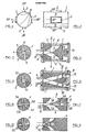
- the fixed housing 1 of the device is a hollow cylinder comprising two opposite rectangular openings 2, 2 for opening with high pressure HP gas and two opposite rectangular openings 3, 3 for opening with expanded gas LP, located to the right of the previous ones but offset 90 ° to them.
- Inside this fixed cylinder 1 rotates an essentially full cylindrical plug 4 in which two elementary channels 5, 5 are made, starting at the periphery by a thin rectangular longitudinal slot 6, 6 and meeting at the center to form a square 7. This meeting evolves along the axis by a transformation from square to round and the terminal circular section 8 comes to rotate just opposite a large coaxial receiving tube 9 and of the same section.
- the general direction of the high pressure gas goes from the outside (in 6) towards the inside (in 7-8 ).
- the feeding phases are limited to the time during which the slots 6, 6 remain, in their rotary scrolling movement, facing the HP lights 2, 2 - while the major part of a revolution, that is to say around 70%, corresponds to the running of the slots 6, 6 over the circumferential extent of the lights BP 3, 3 and of the solid sectors 11 - this reduces the duration and therefore the extent of the gas leak which can occur at the level of the functional clearance existing between the central outlet 8 of the elementary channels 5, 5 and the adjacent end of the receiving tube 9, the leakage being negligible during periods of non-supply of the receiving tube 9.
- peripheral slots 6, 6 being longitudinal and thin, the "laminating transitions are extremely brief and certainly insignificant between the complete closure (slots 6 facing the solid sectors 11 of the wall of the housing 1) and full opening at full section (slots 6 opposite the lights 2 or 3), when the plug 4 rotates, without it being necessary to turn at high speeds.
- FIGS. 5 and 6 differs essentially from the previous embodiment in that the plug 4 comprises elementary channels 5, 5 which begin with orifices 12, 12 oriented parallel to the axis and passing in front of HP lights 13, 13 and BP (not shown) also axial and distributed along a circle on the bottom 14 of the housing 1.
- FIG. 11 shows two conjugate elementary channels 5D, 5E originating in slits peripherals 6, 6 diametrically opposite and opening, through axial openings 8, 8 at opposite ends of the plug 4, in receiving tubes 9A, 9B such as those of FIG. 7. It is clearly seen in FIG. 11 that the elementary channels 5D , 5E have reverse bends.
- the slide 15 is formed from a thin-walled tube very largely indented in two intermediate zones separating three continuous tubular sections: a first end section 16 extending between ends A and B, a median section 17 extending between ends C and D and a second end section 18 extending between ends E and F.
- These successive tubular sections 16-17-18 are joined by longitudinal bars 19 which on the one hand they join together to make the drawer 15 a one-piece piece in the form of a perforated hollow cylinder and which on the other hand form between them large notches 20 and 21 extending respectively between the ends BC and the ends DE .
- a transverse partition 22 Inside the median tubular section 17 is fixed a transverse partition 22 whose role and details will appear in the following.
- the drawer 15 thus designed slides in a fixed sheath 23 to which one or more pulsating receiving tubes are connected (not shown on the demki, but which may be located in the extension of the sheath 23 on one or both sides).
- a fixed sheath 23 Through the wall of this fixed sheath 23 are practiced lights at three levels extending along the axis: a first set of lateral gas inlet lights HP 24 extending axially between edges G and H; a set of median gas outlet lights BP 25 extend axially between edges 1 and J; a second set of lateral gas inlet lights HP 26 extending axially between edges K and L.
- the sliding drawer has been fitted with an air spring which, in the embodiment illustrated in FIG. 13, consists of a piston 27 integral with the partition 22 and movable in a cylinder 28 , the opposite faces of the piston 27 delimiting with the bottoms facing the cylinder 28 two sealed compartments 29-30 with variable volumes in opposite directions: when the drawer 15 moves to the left of the drawing - and consequently the piston 27 also since it is an integral part of it - the gas filling the compartment 29 is compressed while the gas filling the compartment 30 expands.
- the opposite phenomena occur when moving to the right of the drawer 15 and its piston 27: the compartment 29 expands while the compartment 30 compresses, reversing the direction of the resulting force exerted on the piston 27.
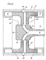
- the peripheral element 32 of the fixed body 31 comprises, in its transverse median part, HP gas inlet ports 39 and, in its center, on either side of the sliding body 37, a first gas outlet opening BP 40 and a second BP gas outlet opening 41.
- the central core 35 of this fixed body 31 is hollowed out and has channels 42 which begin with orifices 43 located at the right of the HP inlet lights 39 and which terminate jointly in a common channel 44, which can itself be a pulsating separator tube or else connect to it.
- the sliding body 37 has radial channels 45 which can, in one position (that which is illustrated), put the channels 42 in communication with the HP inlet lights 39 and, in another position away from the previous on one side or the other, put these channels 42 to drain either by the BP outlet 40 (sliding body 37 shifted to the right), or by the BP outlet 41 (sliding body 37 shifted to the left).
- the exciting force of the reciprocating movement of the drawer 37 comes from the fact that, when the latter approaches a end and puts the tube 44 to the drain by 40 or 41 as the case may be, the LP gas which leaves the orifices 43 must "take the bend to escape, which provides an impulse in the direction of the movement because the gas flow comes strike the corresponding face of the movable drawer 37 and is deflected by it towards the outlet 40 or 41.
Landscapes
- Engineering & Computer Science (AREA)
- Physics & Mathematics (AREA)
- Mechanical Engineering (AREA)
- Thermal Sciences (AREA)
- General Engineering & Computer Science (AREA)
- Multiple-Way Valves (AREA)
- Physical Or Chemical Processes And Apparatus (AREA)
Applications Claiming Priority (2)
| Application Number | Priority Date | Filing Date | Title |
|---|---|---|---|
| FR8007472 | 1980-04-02 | ||
| FR8007472A FR2479919A1 (fr) | 1980-04-02 | 1980-04-02 | Perfectionnements aux separateurs thermiques a distributeur mobile |
Publications (2)
| Publication Number | Publication Date |
|---|---|
| EP0037772A1 EP0037772A1 (fr) | 1981-10-14 |
| EP0037772B1 true EP0037772B1 (fr) | 1983-06-22 |
Family
ID=9240473
Family Applications (1)
| Application Number | Title | Priority Date | Filing Date |
|---|---|---|---|
| EP81400502A Expired EP0037772B1 (fr) | 1980-04-02 | 1981-03-27 | Séparateur thermique à distributeur mobile |
Country Status (5)
| Country | Link |
|---|---|
| US (1) | US4383423A (https=) |
| EP (1) | EP0037772B1 (https=) |
| JP (1) | JPS576268A (https=) |
| DE (1) | DE3160462D1 (https=) |
| FR (1) | FR2479919A1 (https=) |
Families Citing this family (9)
| Publication number | Priority date | Publication date | Assignee | Title |
|---|---|---|---|---|
| US4802508A (en) * | 1988-03-31 | 1989-02-07 | Pacific Biosystems, Inc. | Cyclically varying pulsating fluid supply system |
| US5412950A (en) * | 1993-07-27 | 1995-05-09 | Hu; Zhimin | Energy recovery system |
| JPH10506150A (ja) * | 1994-08-01 | 1998-06-16 | フランツ ヘーマン、 | 非平衡軽量合金及び製品のために選択される処理 |
| US6089026A (en) * | 1999-03-26 | 2000-07-18 | Hu; Zhimin | Gaseous wave refrigeration device with flow regulator |
| CN100434833C (zh) * | 2004-06-29 | 2008-11-19 | 西安交通大学 | 背压式轴流气波制冷机 |
| CN108150537B (zh) * | 2017-12-04 | 2024-04-09 | 陕西仙童科技有限公司 | 一种无阀气体轴承装置 |
| USD916318S1 (en) * | 2019-03-12 | 2021-04-13 | Building Products Development LLC | Thermal separator |
| USD917072S1 (en) * | 2019-03-12 | 2021-04-20 | Building Products Development LLC | Thermal separator |
| CN113606809B (zh) * | 2021-08-11 | 2022-05-20 | 大连理工大学 | 轴流型自循环式气波制冷装置与方法 |
Family Cites Families (11)
| Publication number | Priority date | Publication date | Assignee | Title |
|---|---|---|---|---|
| US2605619A (en) * | 1950-01-20 | 1952-08-05 | James T Serduke | Apparatus for cooling gases |
| US2825204A (en) * | 1951-05-30 | 1958-03-04 | Snecma | Jet propulsion units |
| US3146798A (en) * | 1961-10-30 | 1964-09-01 | United States Steel Corp | Flow controller |
| US3182686A (en) * | 1962-03-28 | 1965-05-11 | Sperry Rand Corp | Transducer |
| US3314244A (en) * | 1966-04-26 | 1967-04-18 | Garrett Corp | Pulse tube refrigeration with a fluid switching means |
| FR1555617A (https=) * | 1967-09-07 | 1969-01-31 | ||
| GB1239166A (https=) * | 1968-08-05 | 1971-07-14 | ||
| FR1588234A (https=) * | 1968-08-05 | 1970-04-10 | ||
| FR2155925B1 (https=) * | 1971-10-15 | 1974-05-31 | Bertin & Cie | |
| FR2311967A1 (fr) * | 1975-05-23 | 1976-12-17 | Allinquant Fernand | Perfectionnements aux ressorts pneumatiques |
| US3992898A (en) * | 1975-06-23 | 1976-11-23 | Carrier Corporation | Movable expansion valve |
-
1980
- 1980-04-02 FR FR8007472A patent/FR2479919A1/fr active Granted
-
1981
- 1981-03-26 US US06/247,735 patent/US4383423A/en not_active Expired - Fee Related
- 1981-03-27 DE DE8181400502T patent/DE3160462D1/de not_active Expired
- 1981-03-27 EP EP81400502A patent/EP0037772B1/fr not_active Expired
- 1981-04-01 JP JP4732981A patent/JPS576268A/ja active Pending
Also Published As
| Publication number | Publication date |
|---|---|
| JPS576268A (en) | 1982-01-13 |
| FR2479919A1 (fr) | 1981-10-09 |
| DE3160462D1 (en) | 1983-07-28 |
| FR2479919B1 (https=) | 1983-11-18 |
| US4383423A (en) | 1983-05-17 |
| EP0037772A1 (fr) | 1981-10-14 |
Similar Documents
| Publication | Publication Date | Title |
|---|---|---|
| EP0037772B1 (fr) | Séparateur thermique à distributeur mobile | |
| CA2475081C (fr) | Dispositif de controle de jeu dans une turbine a gaz | |
| WO2007068134A2 (fr) | Dispositif de generation de froid et de chaleur par effet magneto-calorique | |
| EP0942156A1 (fr) | Organe d'échappement à échangeur de chaleur | |
| CH654651A5 (fr) | Appareil generateur de chaleur utilisant des moyens rotatifs multietages. | |
| EP0816639A1 (fr) | Dispositif de souflage de gaz de réglage de jeux dans une turbomachine | |
| EP0524111B1 (fr) | Dispositif pour le traitement thermique de fils en mouvement | |
| EP0289435B1 (fr) | Four de traitement thermique sous vide à refroidissement par courant de gaz | |
| FR2837321A1 (fr) | Disjoncteur haute tension comprenant un clapet de decompression | |
| WO1985005218A1 (fr) | Dispositif interrupteur a ecran de coupure d'arc | |
| EP0081405B1 (fr) | Dispositif annulaire de joint d'usure et d'étanchéité refroidi par l'air pour aubage de roue de turbine à gaz ou de compresseur | |
| FR2574165A1 (fr) | Appareil de chauffage a arc-plasma pour chauffer de grandes quantites d'air, notamment a des fins de sechage de materiaux bruts | |
| EP3902436B1 (fr) | Appareil de coiffure avec embout de prehension pour le refroidissement du moteur | |
| FR2589194A1 (fr) | Filtre pour la separation de particules solides contenues dans les gaz d'echappement de moteurs diesel | |
| FR2989774A1 (fr) | Dispositif reducteur de bruit pour arme a feu | |
| FR2667932A1 (fr) | Dispositif de chauffage d'un liquide lave-glace, notamment pour vehicule automobile. | |
| EP0022021B1 (fr) | Moteur hydraulique à piston alternatif | |
| FR3069884A1 (fr) | Moteur a source chaude externe a boisseaux | |
| EP1717432B1 (fr) | Tuyère d'éjection orientable d'un moteur d'aéronef | |
| FR2776207A1 (fr) | Installation de traitement de gaz par filtre rotatif adsorbant | |
| BE1004612A6 (fr) | Dispositif de prechauffage d'une busette de coulee d'un metal en fusion. | |
| BE645799A (https=) | ||
| FR2717223A1 (fr) | Dispositif d'échappement pour moteur à combustion interne. | |
| WO2025257802A1 (fr) | Dispositif modérateur de son pour arme à feu et arme à feu comportant un tel dispositif | |
| WO2025061326A1 (fr) | Dispositif de commande fluidique et machine magnétocalorique comportant ledit dispositif de commande fluidique |
Legal Events
| Date | Code | Title | Description |
|---|---|---|---|
| PUAI | Public reference made under article 153(3) epc to a published international application that has entered the european phase |
Free format text: ORIGINAL CODE: 0009012 |
|
| AK | Designated contracting states |
Designated state(s): CH DE FR GB IT |
|
| 17P | Request for examination filed |
Effective date: 19820401 |
|
| GRAA | (expected) grant |
Free format text: ORIGINAL CODE: 0009210 |
|
| AK | Designated contracting states |
Designated state(s): CH DE FR GB LI |
|
| REF | Corresponds to: |
Ref document number: 3160462 Country of ref document: DE Date of ref document: 19830728 |
|
| PG25 | Lapsed in a contracting state [announced via postgrant information from national office to epo] |
Ref country code: LI Effective date: 19840331 Ref country code: CH Effective date: 19840331 |
|
| PGFP | Annual fee paid to national office [announced via postgrant information from national office to epo] |
Ref country code: FR Payment date: 19840424 Year of fee payment: 4 |
|
| PLBE | No opposition filed within time limit |
Free format text: ORIGINAL CODE: 0009261 |
|
| STAA | Information on the status of an ep patent application or granted ep patent |
Free format text: STATUS: NO OPPOSITION FILED WITHIN TIME LIMIT |
|
| 26N | No opposition filed | ||
| REG | Reference to a national code |
Ref country code: CH Ref legal event code: PL |
|
| PG25 | Lapsed in a contracting state [announced via postgrant information from national office to epo] |
Ref country code: DE Effective date: 19841201 |
|
| GBPC | Gb: european patent ceased through non-payment of renewal fee | ||
| ITF | It: translation for a ep patent filed | ||
| PG25 | Lapsed in a contracting state [announced via postgrant information from national office to epo] |
Ref country code: GB Effective date: 19881118 |
|
| PG25 | Lapsed in a contracting state [announced via postgrant information from national office to epo] |
Ref country code: FR Free format text: LAPSE BECAUSE OF NON-PAYMENT OF DUE FEES Effective date: 19891130 |
|
| REG | Reference to a national code |
Ref country code: FR Ref legal event code: ST |