EP0037219B1 - Apparatus for melting and dispensing thermoplastic material - Google Patents
Apparatus for melting and dispensing thermoplastic material Download PDFInfo
- Publication number
- EP0037219B1 EP0037219B1 EP81301190A EP81301190A EP0037219B1 EP 0037219 B1 EP0037219 B1 EP 0037219B1 EP 81301190 A EP81301190 A EP 81301190A EP 81301190 A EP81301190 A EP 81301190A EP 0037219 B1 EP0037219 B1 EP 0037219B1
- Authority
- EP
- European Patent Office
- Prior art keywords
- temperature
- thermoplastic material
- reservoir
- electrical resistance
- shut
- Prior art date
- Legal status (The legal status is an assumption and is not a legal conclusion. Google has not performed a legal analysis and makes no representation as to the accuracy of the status listed.)
- Expired
Links
Images


Classifications
-
- B—PERFORMING OPERATIONS; TRANSPORTING
- B29—WORKING OF PLASTICS; WORKING OF SUBSTANCES IN A PLASTIC STATE IN GENERAL
- B29B—PREPARATION OR PRETREATMENT OF THE MATERIAL TO BE SHAPED; MAKING GRANULES OR PREFORMS; RECOVERY OF PLASTICS OR OTHER CONSTITUENTS OF WASTE MATERIAL CONTAINING PLASTICS
- B29B13/00—Conditioning or physical treatment of the material to be shaped
- B29B13/02—Conditioning or physical treatment of the material to be shaped by heating
- B29B13/022—Melting the material to be shaped
Definitions
- This invention relates to an apparatus for melting and dispensing thermoplastic material according to the precharacterising part of claim 1.
- Such an apparatus is known from US-A-3981416.
- Thermoplastic material is commonly used today as an adhesive.
- thermoplastic material as an adhesive for constructing packages.
- An article is initially placed in a partially errected carton.
- molten thermoplastic material is applied to the carton flaps which are then folded for adhesively joining the flaps together so that the article is sealed in the carton once the molten thermoplastic material solidifies.
- Hot melt adhesives are also used during the assembly of many products, such as automobiles, electronic components, electrical equipment, appliances, furniture, aircraft subassemblies, and products wherein a metal-to-metal bond is needed.
- Thermoplastic material is usually supplied in the form of solid chunks which must be melted to the molten state before the thermoplastic material is used.
- Various types of apparatus are known for melting solid thermoplastic material to the molten state and for dispensing the molten thermoplastic material to an applicator 'or dispenser.
- One such apparatus suitable for melting and dispensing thermoplastic material is shown in US-A-3,981,416 which is owned by the assignee of the present invention, and the disclosure of that patent is incorporated as if fully set forth herein.
- thermoplastic material melting and dispensing apparatus shown in US-A-3,981,416 includes a hopper into which solid thermoplastic material is deposited.
- the hopper feeds the solid thermoplastic material to a grid melter.
- Electrical resistance heaters heat the grid melter for melting the thermoplastic material.
- the molten thermoplastic material flows through the grid melter to a reservoir.
- Electrical resistance heaters heat the reservoir for maintaining the thermoplastic material in the molten state.
- the molten thermoplastic material is pumped from the reservoir to an applicator or dispenser.
- thermoplastic material It is desirable to rapidly melt the solid thermoplastic material and to maintain only a small reservoir of molten thermoplastic material in order to reduce the length of time during which molten thermoplastic material is exposed to oxygen and heat so that degradation of the thermoplastic material is minimized.
- the maximum temperature of the electrical resistance heaters which pass through the grid melter and which are disposed in the walls of the reservoir are capable of heating the grid melter and the reservoir to a temperature which generally exceeds the flash point of the thermoplastic material.
- the maximum temperature of the grid melter and the reservoir may be on the order of 800°F (426.7°C), whereas the flash point of the thermoplastic material may be 650°F (343.3°C). Consequently, thermostatically controlled circuits are used for energizing the electrical resistance heaters which pass through the grid melter and which are disposed in the walls of the reservoir in order to rapidly bring the grid melter up to the temperature for melting the solid thermoplastic material and to rapidly bring the reservoir up to the temperature for maintaining the thermoplastic material in a molten state but to prevent the temperature of the grid melter or the reservoir from reaching the flash point of the thermoplastic material.
- thermoplastic material melts at one temperature, for example, 425°F .(218.4°C), and freezes at a lower temperature, such as 375°F (190.6°C).
- the thermostatically controlled circuits generally include thermostats of either the bimetal or the bulb type. One thermostat is located near the grid melter and another thermostat is located near the reservoir for sensing the temperature of the molten thermoplastic material. Each thermostat in turn energizes a contactor for connecting a power source to the electrical resistance heaters when the temperature of the molten thermoplastic material is below a preselected thermostat temperature setting.
- thermostats can fail, for example, the contacts of either bimetal thermostat can weld closed.
- the use of bulb thermostats is preferred since such thermostats per se are inherently fail-safe, that is, the gas within either bulb thermostat vents off if the bulb ruptures. Nevertheless, the bulbs generally actuate microswitches which in turn energize the contactors for connecting the power source to the electrical resistance heaters. There is a possibility that the microswitches can fail, for example, the contacts of a microswitch can weld closed.
- the contactors can fail, for example, the contacts of a contactor can weld closed or the spring which is used for opening the contacts when the contactor is de-energized can break. If a failure occurs, the electrical resistance heaters continue to be energized by the power source after the preselected thermostat temperature setting is reached. As a result, the temperature of the grid melter or the reservoir heated by the electrical resistance heaters rises above the preselected thermostat temperature setting toward the flash point of the thermoplastic material, thereby creating a risk of fire or explosion.
- the fail-safe circuits heretofore used in thermoplastic material melting and dispensing apparatus can be classified as being either manually resettable or disposable.
- Known manually resettable fail-safe circuits have a form similar to thermal overload circuits generally used in small electrical motors as shown in US-A-2,223,729, for example.
- Disposable fail-safe circuits include fuses having contacts joined by eutectic solder.
- a common characteristic of these fail-safe circuits is that current flows from the power source through the manually resettable or disposable element to the electrical resistance heaters.
- the manually resettable and disposable elements are capable of operating for prolonged periods of time without failure only at a nominal voltage and current, such as 120 volts and 10 amps.
- a safety circuit having a switching arrangement composed of a heatable switching element and an electrical resistance heating element coaxial with the switching element.
- the safety circuit is disclosed as for use with an electric heater, electric motor or the like. No indication is made in the document as to whether the safety circuit is for use with a nominal power source or for a high throughput apparatus which requires large electrical resistance heaters.
- thermoplastic material melting and dispensing apparatus a fail-safe thermostatically controlled circuit for use in high throughout thermoplastic material melting and dispensing apparatus has not been available so far as is known.
- apparatus for melting and dispensing thermoplastic material including means heated by at least one electrical resistance heater for melting solid thermoplastic material and maintaining said thermoplastic material in a molten state until the molten thermoplastic material is dispensed and a thermostatically controlled circuit for connecting a high voltage and current power source to the or each electrical resistance heater if the temperature of the molten thermoplastic material is below a preselected thermostat temperature setting, characterised in that the thermostatically controlled circuit comprises a fusible element through which the power source is connected to the or each electrical resistance heater, heat generating means and a shut-off temperature detector for sensing the temperature of the molten thermoplastic material, the shut-off temperature detector causing the heat generating means to be connected to the power source if the temperature of the molten thermoplastic material reaches a predetermined shut-off temperature so that the heat generating means generates heat for melting the fusible element, thereby disconnecting the power source from the electrical resistance heater.
- the thermoplastic material melting and dispensing apparatus preferably includes a hopper into which solid thermoplastic material is deposited.
- the hopper feeds the solid thermoplastic material to the means heated by at least one electrical resistance heater for melting the solid thermoplastic material and maintaining the thermoplastic material in a molten state until the molten thermoplastic material is pumped to an applicator or dispenser.
- the hopper feeds the solid thermoplastic material to a grid melter which is heated by one or more electrical resistance heaters for melting the solid thermoplastic material.
- the molten thermoplastic material preferably flows from the grid melter to a reservoir which is also heated by one or more electrical resistance heaters for maintaining the thermoplastic material. in a molten state until the molten thermoplastic material is pumped to the applicator or dispenser.
- the at least one electrical resistance heater included in the means for melting the solid thermoplastic material and maintaining the thermoplastic material in a molten state is energised by the thermostatically controlled circuit which includes fail-safe circuitry.
- the fail-safe thermostatically controlled circuit includes a manually adjustable thermostat for sensing the temperature of the molten thermoplastic material in order to connect a high voltage and current power source through the fusible element included in the fail-safe circuitry to the electrical resistance heaters for energising the electrical resistance heaters when the temperature of the molten thermoplastic material is below a preselected thermostat temperature setting.
- the shut-off temperature detector is in the form of a thermostat which has normally open contacts which are closed when the temperature of the molten thermoplastic material reaches the predetermined shut-off temperature which is above the preselected thermostat temperature setting.
- the shut-off temperature detector preferably energises the heat generating means element, such as a resistor, which is connected through the contacts of the shut-off temperature detector to the power source, for melting the fusible element when the predetermined shut-off temperature is reached.
- one fail-safe thermostatically controlled circuit is provided for energising the electrical resistance heaters which pass through the grid melter, and another fail-safe thermostatically controlled circuit is provided for energising the electrical resistance heaters which are disposed in the walls of the reservoir.
- the heat generating element included in the fail-safe circuitry comprises a wire resistor wrapped around a ceramic tube.
- the wire resistor and the ceramic tube are encapsulated in epoxy or other insulative material.
- the fusible element is then placed within the ceramic tube.
- the resistor is electrically insulated and is electrically isolated from the fusible element.
- air can circulate through the ceramic tube for dissipating heat which is generated internally by current flowing through the fusible element during operation of the fail-safe thermostatically controlled circuit, thereby avoiding melting of the fusible element due to internally generated heat and preventing nuisance tripping.
- the invention provides a fail-safe thermostatically controlled circuit for a high-throughput apparatus for melting and dispensing thermoplastic material.
- the fusible element included in the fail-safe circuitry allows use of a high voltage and current, for example, 240 volts and 15 amps, for energising the at least one electrical resistance heater included in the means for melting the solid thermoplastic material and maintaining the thermoplastic material in a molten state so as to overcome the limitation of heretofore used fail-safe circuits which cannot be used a higher than 120 volts and 10 amps.
- the fail-safe circuitry of the invention including the fusible element, shut-off temperature sensor, and heat generating element, comprises very effective fail-safe circuitry which can be constructed at relatively low cost and easily incorporated into thermostatically controlled circuits of high-throughput thermoplastic material melting and dispensing apparatus.
- thermoplastic material melting and dispensing apparatus is generally indicated by the numeral 10 in Figure 1.
- the apparatus for melting and dispensing thermoplastic material includes a housing 11 in which there is located a hopper 12, a grid melter 13, a reservoir 14, a pump 15, and a manifold block 16.
- thermoplastic material 17 in the form of chunks is deposited in the top of hopper 12 through a removable cover 18.
- Hopper 12 comprises a vertical tube 19, the bottom 20 of which is open. Solid thermoplastic material 17 deposited in vertical tube 19 of hopper 12 is fed through bottom 20 of the hopper into contact with the top surface of grid melter 13.
- Grid melter 13 is heated as will be described later so that contact of solid thermoplastic material 17 with the top surface of the grid melter causes the solid thermoplastic material to melt, thereby converting the solid thermoplastic material into a molten state. Molten thermoplastic material 21 then flows downwardly through passageways 22 in grid melter 13 to reservoir 14 located immediately beneath the grid melter.
- reservoir 14 has sloping walls 23, 24, and 25 which direct molten thermoplastic material 21 toward the inlet 26 of pump 15.
- Molten thermoplastic material 21 is pumped through the outlet 27 of pump 15 into manifold block 16 from whence the molten thermoplastic material is directed to one or more conventional applicators or dispensers 28 via hoses or conduits 29 as shown in Fig. 1.
- Further details of the thermoplastic material melting and dispensing apparatus shown in Figs. 1-3 appear in aforementioned U.S. Patent 3,981,416.
- One or more bores 30 extend through a wall 31 as well as through the base portion of each row of grid melter protrusions 32 included in grid melter 13.
- An electrical resistance heater 33 is mounted within each bore 30 so that an electrical resistance heater extends into and through wall 31 and the base portion of each row of grid melter protrusions 32.
- Grid melter thermostat 35 is located in such a position as to faithfully sense the temperature of grid melter 13.
- Grid melter thermostat 35 is used for maintaining the temperature of grid melter 13 at a preselected thermostat temperature setting which can be manually adjusted by means of a grid melter temperature dial 36 on a control panel 37 of housing 11 as shown in Fig. 1.
- a grid melter temperature dial 36 on a control panel 37 of housing 11 as shown in Fig. 1.
- Transverse bore 38 accommodates a grid melter temperature measuring gauge 39 of con- ven.tional structure, the front face 40 of which is located upon control panel 37 of housing 11.
- each electrical resistance heater 41 which is disposed in walls 23-25 of reservoir 14 there is an electrical contact (not shown) by means of which the individual electrical resistance heaters may be electrically connected to the fail-safe thermostatically controlled circuit of the invention which will be described later.
- a reservoir thermostat 43 preferably a bulb thermostat, is mounted for controlling the temperature of the reservoir as described later.
- Reservoir thermostat 43 is located in such a position as to faithfully sense the temperature of reservoir 14. Reservoir thermostat 43 is used for maintaining the temperature of reservoir 14 at a preselected thermostat temperature setting which can be manually adjusted by means of a reservoir temperature dial 44 on control panel 37 of housing 11 as shown in Fig. 1. There is preferably also a transverse bore 45 in wall 25 of reservoir 14. Transverse bore 45 accommodates a reservoir temperature measuring gauge 46 of conventional structure, the front face 47 of which is located upon control panel 37 of housing 11.
- a grid melter shut-off temperature detector 48 preferably a thermostat having normally open contacts, is located on grid melter 13 at a position such as shown in Figure 2 chosen for faithfully sensing the temperature of molten thermoplastic material 21 in the region of the grid melter.
- a reservoir shut-off temperature detector 49 preferably a thermostat having normally open contacts, is located on a base portion 50 of reservoir 14 as shown in Figure 2 chosen for faithfully sensing the temperature of molten thermoplastic material 21 in the reservoir.
- An embodiment of a fail-safe thermostatically controlled circuit for energising electrical resistance heaters 33 which heat grid melter 13 and the electrical resistance heaters 41 which heat reservoir 14 comprising the means for melting the thermoplastic material and maintaining the thermoplastic material in a molten state as shown in Figure 4.
- one fail-safe thermostatically controlled circuit is preferably provided for electrical resistance heaters 33 which pass through grid melter 13
- another fail-safe thermostatically controlled circuit is preferably provided for energising electrical resistance heaters 41 which are disposed in walls 23-25 of reservoir 14.
- grid melter thermostat 35 is generally set at the melting temperature or slightly above the melting temperature of thermoplastic material 17.
- Reservoir thermostat 43 is set at a temperature which will maintain molten thermoplastic material 21 in the molten state with a minimum of thermal degradation.
- there may be a single fail-safe thermostatically controlled circuit for energizing the electrical resistance heaters in both the grid melter and the reservoir for example, in a case where the melting temperature of the solid thermoplastic material and the freezing temperature of molten thermoplastic material are substantially the same. It is also contemplated that the reservoir may not need electrical resistance heaters.
- the fail-safe thermostatically controlled circuit shown in Fig. 4 can be easily modified for use in any of the above-enumerated situations.
- the fail-safe thermostatically controlled circuit of the invention which is contained in housing 11 behind control panel 37, connects a high voltage and current power source, such as a 240 volt, 15 amp alternating current power source, to electrical resistance heaters 33 which pass through grid melter 13 and electrical resistance heaters 41 which are disposed in walls 23-25 or reservoir 14.
- a high voltage and current power source such as a 240 volt, 15 amp alternating current power source
- Grid melter thermostat 35 mounted in bore 34 of grid melter 13, which is manually adjusted by means of grid melter temperature dial 36 for setting the desired operating temperature of grid melter 13, and reservoir thermostat 43 mounted in bore 42 of reservoir 14, which is manually adjusted by means of reservoir temperature dial 44 for setting the desired operating temperature of reservoir 14, normally cycle on and off for maintaining the grid melter and the reservoir at the desired temperatures, such as 400°F (204.4°C) and 375°F (190.6°C), respectively.
- grid melter thermostat 35 When the temperature of grid melter 13 is below the preselected grid melter thermostat temperature setting, grid melter thermostat 35 preferably closes a microswitch 61.
- reservoir thermostat 43 preferably closes a microswitch 61'. When microswitch 61 or 61' is closed, the coil of a contactor 62 or 62' is connected to the power source.
- the coil of contactor 62 or 62' When the coil of contactor 62 or 62' is connected to the power source, the coil of contactor 62 or 62' is energized for closing normally open contacts 63 or 63'. When contacts 63 or 63' are closed, the power source is connected through a fusible element 64 or 64' included in fail-safe circuitry 65 or 65' to elec- tricat resistance heaters 33 which pass through grid melter 13 or electrical resistance heaters 41 which are disposed in walls 23-25 of reservoir 14 for heating the grid melter or the reservoir.
- grid melter thermostat 35 opens microswitch 61, thereby de-energizing the coil of contactor 62 so that contacts 63 are opened.
- reservoir thermostat 43 opens microswitch 61', thereby de-energizing the coil of contactor 62' so that contacts 63' are opened.
- microswitch 61 or 61' becomes welded closed or contacts 63 or 63' of contactor 62 or 62' become welded closed or spring 66 or 66' of contactor 62 or 62' breaks or some other failure occurs, the power source could remain connected through fusible element 64 or 64' to electrical resistance heaters 33 or 41.
- electrical resistance heaters 33 which pass through grid melter 13 will continue to heat the grid melter beyond the preselected grid melter thermostat temperature setting toward the predetermined grid melter shut-off temperature, for example, 500°F (260°C), whereupon grid melter shut-off temperature detector 48 is actuated; or electrical resistance heaters 41 which are disposed in walls 23-25 of reservoir 14 will continue to heat the reservoir beyond the preselected reservoir thermostat temperature setting toward the predetermined reservoir shut-off temperature, for example, 500° (260°C), whereupon reservoir shut-off temperature detector 49 is actuated.
- grid melter shut-off temperature detector 48 is preferably a thermostat having normally open contacts which are closed when grid melter 13 reaches the predetermined grid melter shut-off temperature
- reservoir shut-off temperature detector 49 is preferably a thermostat having normally open contacts which are closed when the reservoir reaches the predetermined reservoir shut-off temperature. If the predetermined grid melter shut-off temperature is reached, the contacts of grid melter shut-off temperature detector 48 are closed, and, if the predetermined reservoir shut-off temperature is reached, the contacts of reservoir shut-off temperature detector 49 are closed.
- a heat generating element 67 such as an eight watt, 3000 ohm resistor
- a heat generating element 67' such as an eight watt, 3000 ohm resistor
- Fail-safe circuitry 65 or 65' which includes fusible element 64 or 64', shut-off temperature detector 48 or 49, and heat generating element 67 or 67', permanently disconnects the power source from the electrical resistance heaters 33 which pass through grid melter 13 or electrical resistance heaters 41 which are disposed in walls 23-25 of reservoir 14, that is, fail-safe circuitry 65 or 65' is not manually resettable. In order to be able to re-energize electrical resistance heaters 33 or 41, fusible element 64 or 64' must be replaced.
- Fusible element 64 or 64' and heat generating element 67 or 67' is shown in Fig. 5.
- Fusible element 64 or 64' includes a casing 68.
- a lead 69 is mounted in an insulator bushing 70 held in casing 68 by sealing compound 71.
- Insulator bushing 70 has a nose portion 72 for retaining a trip spring 73.
- Trip spring 73 bears against a star contact 74 which is in contact with a first conductive disc 75.
- Casing 68 holds thermal pellets 76 which are contained between a lead 77 and a second conductive disc 78.
- a compression spring 79 is sandwiched between discs 75 and 78 and establishes continuity between lead 69 and lead 77 through star contact 74, disc 75, compression spring 79, disc 78, and thermal pellets 76.
- fusible element 64 or 64' is preferably disposed in a ceramic tube 82 in such a way that there is an annular air passage 80 between fusible element 64 or 64' and ceramic tube 82.
- the purpose of annular air passage 80 is for allowing air to circulate over the surface of fusible element 64 or 64' for dissipating heat generated internally by current flowing through the fusible element, that is, from lead 69 through star contact 74, disc 75, compression spring 79, disc 78, and thermal pellets 76 to lead 77.
- Heat generating element 67 or 67' preferably comprises a resistive wire 81 wound around the outside of ceramic tube 82. Resistive wire 81 is first wound around ceramic tube 82 and then encapsulated in epoxy or other electrically insulative material before fusible element 64 or 64' is placed in the ceramic tube. As a result, resistive wire 81 is electrically insulated as well as being electrically isolated from fusible element 64 or 64' by the encapsulation and ceramic tube 82. With reference to Figs.
- heat generating element 67 or 67' is connected to the power source and generates heat which causes thermal pellets 76 in fusible element 64 or 64' to melt so that trip spring 73 pushes star contact 74 and disc 75 away from lead 69, thereby disconnecting the power source from electrical resistance heaters 33 which pass through grid melter 13 or electrical resistance heaters 41 which are disposed in walls 23-25 of reservoir 14.
- the invention provides a fail-safe thermostatically controlled circuit for a high-throughput apparatus for melting and dispensing thermoplastic material.
- the fusible element included in the fail-safe circuitry allows use of a high voltage and current, for example, 240 volts and 15 amps, for energizing the electrical resistance heaters included in the means for melting the solid thermoplastic material and maintaining the thermoplastic material in a molten state.
- the fail-safe circuitry of the invention including the fusible element, shut-off temperature sensor, and heat generating element, comprises very effective fail-safe circuitry which can be constructed at relatively low cost and easily incorporated into thermostatically controlled circuits of high-throughput apparatus for melting and dispensing thermoplastic material.
Landscapes
- Physics & Mathematics (AREA)
- Thermal Sciences (AREA)
- Engineering & Computer Science (AREA)
- Mechanical Engineering (AREA)
- Control Of Resistance Heating (AREA)
- Control Of Temperature (AREA)
- Processing And Handling Of Plastics And Other Materials For Molding In General (AREA)
Description
- This invention relates to an apparatus for melting and dispensing thermoplastic material according to the precharacterising part of claim 1. Such an apparatus is known from US-A-3981416.
- Thermoplastic material is commonly used today as an adhesive. Consider, for example, the use of thermoplastic material as an adhesive for constructing packages. An article is initially placed in a partially errected carton. Next, molten thermoplastic material is applied to the carton flaps which are then folded for adhesively joining the flaps together so that the article is sealed in the carton once the molten thermoplastic material solidifies. Hot melt adhesives are also used during the assembly of many products, such as automobiles, electronic components, electrical equipment, appliances, furniture, aircraft subassemblies, and products wherein a metal-to-metal bond is needed.
- Thermoplastic material is usually supplied in the form of solid chunks which must be melted to the molten state before the thermoplastic material is used. Various types of apparatus are known for melting solid thermoplastic material to the molten state and for dispensing the molten thermoplastic material to an applicator 'or dispenser. One such apparatus suitable for melting and dispensing thermoplastic material is shown in US-A-3,981,416 which is owned by the assignee of the present invention, and the disclosure of that patent is incorporated as if fully set forth herein.
- The thermoplastic material melting and dispensing apparatus shown in US-A-3,981,416 includes a hopper into which solid thermoplastic material is deposited. The hopper feeds the solid thermoplastic material to a grid melter. Electrical resistance heaters heat the grid melter for melting the thermoplastic material. The molten thermoplastic material flows through the grid melter to a reservoir. Electrical resistance heaters heat the reservoir for maintaining the thermoplastic material in the molten state. The molten thermoplastic material is pumped from the reservoir to an applicator or dispenser.
- It is desirable to rapidly melt the solid thermoplastic material and to maintain only a small reservoir of molten thermoplastic material in order to reduce the length of time during which molten thermoplastic material is exposed to oxygen and heat so that degradation of the thermoplastic material is minimized. In order to rapidly bring the grid melter up to a temperature for melting the solid thermoplastic material and to rapidly bring the reservoir up to a temperature for maintaining the thermoplastic material in a molten state, the maximum temperature of the electrical resistance heaters which pass through the grid melter and which are disposed in the walls of the reservoir are capable of heating the grid melter and the reservoir to a temperature which generally exceeds the flash point of the thermoplastic material. The maximum temperature of the grid melter and the reservoir, for example, may be on the order of 800°F (426.7°C), whereas the flash point of the thermoplastic material may be 650°F (343.3°C). Consequently, thermostatically controlled circuits are used for energizing the electrical resistance heaters which pass through the grid melter and which are disposed in the walls of the reservoir in order to rapidly bring the grid melter up to the temperature for melting the solid thermoplastic material and to rapidly bring the reservoir up to the temperature for maintaining the thermoplastic material in a molten state but to prevent the temperature of the grid melter or the reservoir from reaching the flash point of the thermoplastic material.
- It is generally desirable to operate the grid melter and the reservoir at different temperatures. In the case of many thermoplastic materials, solid thermoplastic material melts at one temperature, for example, 425°F .(218.4°C), and freezes at a lower temperature, such as 375°F (190.6°C). In the case of such thermoplastic materials, it is preferable to operate the grid melter at a temperature slightly above the melting temperature and the temperature of the reservoir slightly above the freezing temperature. As a result, degradation of molten thermoplastic material in the reservoir is minimized. Therefore, separate thermostatically controlled circuits are provided for energizing the electrical resistance heaters which pass through the grid melter and the electrical resistance heaters which are disposed in the walls of the reservoir.
- The thermostatically controlled circuits generally include thermostats of either the bimetal or the bulb type. One thermostat is located near the grid melter and another thermostat is located near the reservoir for sensing the temperature of the molten thermoplastic material. Each thermostat in turn energizes a contactor for connecting a power source to the electrical resistance heaters when the temperature of the molten thermoplastic material is below a preselected thermostat temperature setting.
- In the case where bimetal thermostats are used, there is a possibility that the thermostats can fail, for example, the contacts of either bimetal thermostat can weld closed. The use of bulb thermostats is preferred since such thermostats per se are inherently fail-safe, that is, the gas within either bulb thermostat vents off if the bulb ruptures. Nevertheless, the bulbs generally actuate microswitches which in turn energize the contactors for connecting the power source to the electrical resistance heaters. There is a possibility that the microswitches can fail, for example, the contacts of a microswitch can weld closed. Furthermore, in either the case where bimetal thermostats are used or the case where bulb thermostate are used, there is a possibility that the contactors can fail, for example, the contacts of a contactor can weld closed or the spring which is used for opening the contacts when the contactor is de-energized can break. If a failure occurs, the electrical resistance heaters continue to be energized by the power source after the preselected thermostat temperature setting is reached. As a result, the temperature of the grid melter or the reservoir heated by the electrical resistance heaters rises above the preselected thermostat temperature setting toward the flash point of the thermoplastic material, thereby creating a risk of fire or explosion.
- In view of the recognized failure problems, various fail-safe circuits have been proposed for avoiding the risk of fire or explosion if the thermostatically controlled circuit fails. However, fail-safe circuits heretofore used have the unfortunate limitation that they cannot be used in conjunction with thermostatically controlled circuits for the grid melter and the reservoir of high-throughput apparatus for melting and dispensing thermoplastic material which are energized at a high voltage and current.
- Generally, the fail-safe circuits heretofore used in thermoplastic material melting and dispensing apparatus can be classified as being either manually resettable or disposable. Known manually resettable fail-safe circuits have a form similar to thermal overload circuits generally used in small electrical motors as shown in US-A-2,223,729, for example. Disposable fail-safe circuits, on the other hand, include fuses having contacts joined by eutectic solder. A common characteristic of these fail-safe circuits is that current flows from the power source through the manually resettable or disposable element to the electrical resistance heaters. However, the manually resettable and disposable elements are capable of operating for prolonged periods of time without failure only at a nominal voltage and current, such as 120 volts and 10 amps. Consequently fail-safe circuits heretofore used have been restricted to apparatus for melting and dispensing thermoplastic material having electrical resistance heaters energized by a 120 volt, 10 amp or other nominal power source. High throughout is not achievable under such conditions, that is, high throughput requires larger electrical resistance heaters energized by a high voltage and current, such as 240 volts and 15 amps.
- In US-A-3794811 a safety circuit is disclosed having a switching arrangement composed of a heatable switching element and an electrical resistance heating element coaxial with the switching element. The safety circuit is disclosed as for use with an electric heater, electric motor or the like. No indication is made in the document as to whether the safety circuit is for use with a nominal power source or for a high throughput apparatus which requires large electrical resistance heaters.
- Heretofore, a fail-safe thermostatically controlled circuit for use in high throughout thermoplastic material melting and dispensing apparatus has not been available so far as is known.
- It is the primary objective of the invention to provide a fail-safe thermostatically controlled circuit for use in a high throughput apparatus for melting and dispensing thermoplastic material. It is also an objective to provide fail-safe circuitry which can be easily incorporated into the thermostatically controlled circuit or circuits which energise the electrical resistance heaters in thermoplastic melting and dispensing apparatus.
- In accordance with the invention, apparatus for melting and dispensing thermoplastic material including means heated by at least one electrical resistance heater for melting solid thermoplastic material and maintaining said thermoplastic material in a molten state until the molten thermoplastic material is dispensed and a thermostatically controlled circuit for connecting a high voltage and current power source to the or each electrical resistance heater if the temperature of the molten thermoplastic material is below a preselected thermostat temperature setting, characterised in that the thermostatically controlled circuit comprises a fusible element through which the power source is connected to the or each electrical resistance heater, heat generating means and a shut-off temperature detector for sensing the temperature of the molten thermoplastic material, the shut-off temperature detector causing the heat generating means to be connected to the power source if the temperature of the molten thermoplastic material reaches a predetermined shut-off temperature so that the heat generating means generates heat for melting the fusible element, thereby disconnecting the power source from the electrical resistance heater.
- The thermoplastic material melting and dispensing apparatus preferably includes a hopper into which solid thermoplastic material is deposited. The hopper feeds the solid thermoplastic material to the means heated by at least one electrical resistance heater for melting the solid thermoplastic material and maintaining the thermoplastic material in a molten state until the molten thermoplastic material is pumped to an applicator or dispenser. Preferably, the hopper feeds the solid thermoplastic material to a grid melter which is heated by one or more electrical resistance heaters for melting the solid thermoplastic material. The molten thermoplastic material preferably flows from the grid melter to a reservoir which is also heated by one or more electrical resistance heaters for maintaining the thermoplastic material. in a molten state until the molten thermoplastic material is pumped to the applicator or dispenser.
- Preferably, the at least one electrical resistance heater included in the means for melting the solid thermoplastic material and maintaining the thermoplastic material in a molten state is energised by the thermostatically controlled circuit which includes fail-safe circuitry. The fail-safe thermostatically controlled circuit includes a manually adjustable thermostat for sensing the temperature of the molten thermoplastic material in order to connect a high voltage and current power source through the fusible element included in the fail-safe circuitry to the electrical resistance heaters for energising the electrical resistance heaters when the temperature of the molten thermoplastic material is below a preselected thermostat temperature setting.
- Preferably the shut-off temperature detector is in the form of a thermostat which has normally open contacts which are closed when the temperature of the molten thermoplastic material reaches the predetermined shut-off temperature which is above the preselected thermostat temperature setting. The shut-off temperature detector preferably energises the heat generating means element, such as a resistor, which is connected through the contacts of the shut-off temperature detector to the power source, for melting the fusible element when the predetermined shut-off temperature is reached. Preferably, one fail-safe thermostatically controlled circuit is provided for energising the electrical resistance heaters which pass through the grid melter, and another fail-safe thermostatically controlled circuit is provided for energising the electrical resistance heaters which are disposed in the walls of the reservoir.
- Preferably the heat generating element included in the fail-safe circuitry comprises a wire resistor wrapped around a ceramic tube. The wire resistor and the ceramic tube are encapsulated in epoxy or other insulative material. The fusible element is then placed within the ceramic tube. By this arrangement, the resistor is electrically insulated and is electrically isolated from the fusible element. Also, air can circulate through the ceramic tube for dissipating heat which is generated internally by current flowing through the fusible element during operation of the fail-safe thermostatically controlled circuit, thereby avoiding melting of the fusible element due to internally generated heat and preventing nuisance tripping.
- The invention provides a fail-safe thermostatically controlled circuit for a high-throughput apparatus for melting and dispensing thermoplastic material. The fusible element included in the fail-safe circuitry allows use of a high voltage and current, for example, 240 volts and 15 amps, for energising the at least one electrical resistance heater included in the means for melting the solid thermoplastic material and maintaining the thermoplastic material in a molten state so as to overcome the limitation of heretofore used fail-safe circuits which cannot be used a higher than 120 volts and 10 amps. The fail-safe circuitry of the invention, including the fusible element, shut-off temperature sensor, and heat generating element, comprises very effective fail-safe circuitry which can be constructed at relatively low cost and easily incorporated into thermostatically controlled circuits of high-throughput thermoplastic material melting and dispensing apparatus.
- An embodiment of a fail-safe thermostatically controlled circuit in accordance with the invention for energising the electrical resistance heaters included in an apparatus for melting and dispensing thermoplastic material will now be described by way of example with reference to the accompanying drawings in which:- :
- Figure 1 is a perspective view of a thermoplastic material melting and dispensing apparatus incorporating the fail-safe thermostatically controlled circuit of the invention;
- Figure 2 is an exploded perspective view of a portion of the apparatus for melting and dispensing thermoplastic material shown in Figure 1;
- Figure 3 is a cross-sectional view taken along line 3-3 in Figure 1;
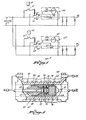
- Figure 4 is a schematic circuit diagram of the fail-safe thermostatically controlled circuit of the apparatus, and
- Figure 5 is a detailed view of several elements of the fail-safe circuitry.
- The thermoplastic material melting and dispensing apparatus is generally indicated by the numeral 10 in Figure 1. As shown in Figures 1 to 3, the apparatus for melting and dispensing thermoplastic material includes a housing 11 in which there is located a
hopper 12, agrid melter 13, areservoir 14, apump 15, and amanifold block 16. - As shown in Figure 3, solid thermoplastic material 17 in the form of chunks is deposited in the top of
hopper 12 through a removable cover 18.Hopper 12 comprises a vertical tube 19, the bottom 20 of which is open. Solid thermoplastic material 17 deposited in vertical tube 19 ofhopper 12 is fed throughbottom 20 of the hopper into contact with the top surface ofgrid melter 13. -
Grid melter 13 is heated as will be described later so that contact of solid thermoplastic material 17 with the top surface of the grid melter causes the solid thermoplastic material to melt, thereby converting the solid thermoplastic material into a molten state. Molten thermoplastic material 21 then flows downwardly through passageways 22 ingrid melter 13 toreservoir 14 located immediately beneath the grid melter. - As shown in Fig. 2,
reservoir 14 has slopingwalls inlet 26 ofpump 15. Molten thermoplastic material 21 is pumped through theoutlet 27 ofpump 15 intomanifold block 16 from whence the molten thermoplastic material is directed to one or more conventional applicators ordispensers 28 via hoses or conduits 29 as shown in Fig. 1. Further details of the thermoplastic material melting and dispensing apparatus shown in Figs. 1-3 appear in aforementioned U.S. Patent 3,981,416. - One or more bores 30 extend through a
wall 31 as well as through the base portion of each row ofgrid melter protrusions 32 included ingrid melter 13. Anelectrical resistance heater 33 is mounted within each bore 30 so that an electrical resistance heater extends into and throughwall 31 and the base portion of each row ofgrid melter protrusions 32. On the end of eachelectrical resistance heater 33 which passes throughgrid melter 13, there is an electrical contact (not shown) by means of which the individual electrical resistance heaters may be electrically connected to the fail-safe thermostatically controlled circuit of the invention which will be described later. There is also abore 34 which extends throughwall 31 ofgrid melter 13 within which a grid melter thermostat 35, preferably a bulb thermostat, is mounted for controlling the temperature of the grid melter as described later. - Grid melter thermostat 35 is located in such a position as to faithfully sense the temperature of
grid melter 13. Grid melter thermostat 35 is used for maintaining the temperature ofgrid melter 13 at a preselected thermostat temperature setting which can be manually adjusted by means of a gridmelter temperature dial 36 on acontrol panel 37 of housing 11 as shown in Fig. 1. There is preferably also a transverse bore 38 inwall 31 ofgrid melter 13. Transverse bore 38 accommodates a grid meltertemperature measuring gauge 39 of con- ven.tional structure, thefront face 40 of which is located uponcontrol panel 37 of housing 11. - Preferably, as shown in Fig. 2, there are also two identical U-shaped
electrical resistance heaters 41 moulded within walls 23-25 ofreservoir 14.Electrical resistance heaters 41 are positioned on opposite sides ofpump 15 for assuring uniform heating of the pump andmanifold block 16. On the end of eachelectrical resistance heater 41 which is disposed in walls 23-25 ofreservoir 14 there is an electrical contact (not shown) by means of which the individual electrical resistance heaters may be electrically connected to the fail-safe thermostatically controlled circuit of the invention which will be described later. There is also abore 42 molded inwall 24 ofreservoir 14 within which areservoir thermostat 43, preferably a bulb thermostat, is mounted for controlling the temperature of the reservoir as described later. -
Reservoir thermostat 43 is located in such a position as to faithfully sense the temperature ofreservoir 14.Reservoir thermostat 43 is used for maintaining the temperature ofreservoir 14 at a preselected thermostat temperature setting which can be manually adjusted by means of a reservoir temperature dial 44 oncontrol panel 37 of housing 11 as shown in Fig. 1. There is preferably also atransverse bore 45 in wall 25 ofreservoir 14. Transverse bore 45 accommodates a reservoirtemperature measuring gauge 46 of conventional structure, thefront face 47 of which is located uponcontrol panel 37 of housing 11. - A grid melter shut-off
temperature detector 48, preferably a thermostat having normally open contacts, is located ongrid melter 13 at a position such as shown in Figure 2 chosen for faithfully sensing the temperature of molten thermoplastic material 21 in the region of the grid melter. Also, a reservoir shut-offtemperature detector 49, preferably a thermostat having normally open contacts, is located on a base portion 50 ofreservoir 14 as shown in Figure 2 chosen for faithfully sensing the temperature of molten thermoplastic material 21 in the reservoir. - An embodiment of a fail-safe thermostatically controlled circuit for energising
electrical resistance heaters 33 which heatgrid melter 13 and theelectrical resistance heaters 41 whichheat reservoir 14 comprising the means for melting the thermoplastic material and maintaining the thermoplastic material in a molten state as shown in Figure 4. As mentioned earlier, one fail-safe thermostatically controlled circuit is preferably provided forelectrical resistance heaters 33 which pass throughgrid melter 13, and another fail-safe thermostatically controlled circuit is preferably provided for energisingelectrical resistance heaters 41 which are disposed in walls 23-25 ofreservoir 14. In operation, grid melter thermostat 35 is generally set at the melting temperature or slightly above the melting temperature of thermoplastic material 17.Reservoir thermostat 43 is set at a temperature which will maintain molten thermoplastic material 21 in the molten state with a minimum of thermal degradation. However, it is contemplated that there may be a single fail-safe thermostatically controlled circuit for energizing the electrical resistance heaters in both the grid melter and the reservoir, for example, in a case where the melting temperature of the solid thermoplastic material and the freezing temperature of molten thermoplastic material are substantially the same. It is also contemplated that the reservoir may not need electrical resistance heaters. The fail-safe thermostatically controlled circuit shown in Fig. 4 can be easily modified for use in any of the above-enumerated situations. - The fail-safe thermostatically controlled circuit of the invention, indicated generally by the numeral 60 in Fig. 4, which is contained in housing 11 behind
control panel 37, connects a high voltage and current power source, such as a 240 volt, 15 amp alternating current power source, toelectrical resistance heaters 33 which pass throughgrid melter 13 andelectrical resistance heaters 41 which are disposed in walls 23-25 orreservoir 14. Grid melter thermostat 35 mounted inbore 34 ofgrid melter 13, which is manually adjusted by means of gridmelter temperature dial 36 for setting the desired operating temperature ofgrid melter 13, andreservoir thermostat 43 mounted inbore 42 ofreservoir 14, which is manually adjusted by means of reservoir temperature dial 44 for setting the desired operating temperature ofreservoir 14, normally cycle on and off for maintaining the grid melter and the reservoir at the desired temperatures, such as 400°F (204.4°C) and 375°F (190.6°C), respectively. When the temperature ofgrid melter 13 is below the preselected grid melter thermostat temperature setting, grid melter thermostat 35 preferably closes amicroswitch 61. Similarly, when the temperature ofreservoir 14 is below the preselected reservoir thermostat temperature setting,reservoir thermostat 43 preferably closes a microswitch 61'. When microswitch 61 or 61' is closed, the coil of acontactor 62 or 62' is connected to the power source. - When the coil of
contactor 62 or 62' is connected to the power source, the coil ofcontactor 62 or 62' is energized for closing normallyopen contacts 63 or 63'. Whencontacts 63 or 63' are closed, the power source is connected through afusible element 64 or 64' included in fail-safe circuitry 65 or 65' to elec-tricat resistance heaters 33 which pass throughgrid melter 13 orelectrical resistance heaters 41 which are disposed in walls 23-25 ofreservoir 14 for heating the grid melter or the reservoir. - When the temperature of
grid melter 13 reaches the preselected grid melter thermostat temperature setting, grid melter thermostat 35 opensmicroswitch 61, thereby de-energizing the coil ofcontactor 62 so thatcontacts 63 are opened. Similarly, when the temperature ofreservoir 14 reaches the preselected reservoir thermostat temperature setting,reservoir thermostat 43 opens microswitch 61', thereby de-energizing the coil of contactor 62' so that contacts 63' are opened. Whencontacts 63 or 63' are opened, the power source is disconnected fromelectrical resistance heaters 33 which pass throughgrid melter 13 orelectrical resistance heaters 41 which are disposed in walls 23-25 ofreservoir 14. If, however, for somereason microswitch 61 or 61' becomes welded closed orcontacts 63 or 63' ofcontactor 62 or 62' become welded closed or spring 66 or 66' ofcontactor 62 or 62' breaks or some other failure occurs, the power source could remain connected throughfusible element 64 or 64' toelectrical resistance heaters - If failure occurs,
electrical resistance heaters 33 which pass throughgrid melter 13 will continue to heat the grid melter beyond the preselected grid melter thermostat temperature setting toward the predetermined grid melter shut-off temperature, for example, 500°F (260°C), whereupon grid melter shut-offtemperature detector 48 is actuated; orelectrical resistance heaters 41 which are disposed in walls 23-25 ofreservoir 14 will continue to heat the reservoir beyond the preselected reservoir thermostat temperature setting toward the predetermined reservoir shut-off temperature, for example, 500° (260°C), whereupon reservoir shut-offtemperature detector 49 is actuated. - As shown in Fig. 4, grid melter shut-off
temperature detector 48 is preferably a thermostat having normally open contacts which are closed whengrid melter 13 reaches the predetermined grid melter shut-off temperature, and reservoir shut-offtemperature detector 49 is preferably a thermostat having normally open contacts which are closed when the reservoir reaches the predetermined reservoir shut-off temperature. If the predetermined grid melter shut-off temperature is reached, the contacts of grid melter shut-offtemperature detector 48 are closed, and, if the predetermined reservoir shut-off temperature is reached, the contacts of reservoir shut-offtemperature detector 49 are closed. When the contacts of grid melter shut-offtemperature detector 48 are closed, aheat generating element 67, such as an eight watt, 3000 ohm resistor, is connected to the power source, and, when the contacts of reservoir shut-offtemperature detector 49 are closed, a heat generating element 67', such as an eight watt, 3000 ohm resistor, is connected to the power source. The heat generated byheat generating element 67 meltsfusible element 64, thereby disconnectingelectrical resistance heaters 33 which pass throughgrid melter 13 from the power source, and the heat generated by heat generating element 67' melts fusible element 64', thereby disconnectingelectrical resistance heaters 41 from the power source. - Fail-
safe circuitry 65 or 65', which includesfusible element 64 or 64', shut-offtemperature detector element 67 or 67', permanently disconnects the power source from theelectrical resistance heaters 33 which pass throughgrid melter 13 orelectrical resistance heaters 41 which are disposed in walls 23-25 ofreservoir 14, that is, fail-safe circuitry 65 or 65' is not manually resettable. In order to be able to re-energizeelectrical resistance heaters fusible element 64 or 64' must be replaced. - The preferred embodiment of the
fusible element 64 or 64' and heat generatingelement 67 or 67' is shown in Fig. 5.Fusible element 64 or 64' includes acasing 68. A lead 69 is mounted in aninsulator bushing 70 held incasing 68 by sealingcompound 71.Insulator bushing 70 has anose portion 72 for retaining atrip spring 73.Trip spring 73 bears against astar contact 74 which is in contact with a firstconductive disc 75.Casing 68 holdsthermal pellets 76 which are contained between a lead 77 and a secondconductive disc 78. Acompression spring 79 is sandwiched betweendiscs lead 69 and lead 77 throughstar contact 74,disc 75,compression spring 79,disc 78, andthermal pellets 76. - As shown in Fig. 5,
fusible element 64 or 64' is preferably disposed in aceramic tube 82 in such a way that there is anannular air passage 80 betweenfusible element 64 or 64' andceramic tube 82. The purpose ofannular air passage 80 is for allowing air to circulate over the surface offusible element 64 or 64' for dissipating heat generated internally by current flowing through the fusible element, that is, fromlead 69 throughstar contact 74,disc 75,compression spring 79,disc 78, andthermal pellets 76 to lead 77. By providingannular air passage 80, nuisance tripping due to melting ofthermal pellets 76 infusible element 64 or 64' due to internally generated heat is avoided. Heat generatingelement 67 or 67' preferably comprises aresistive wire 81 wound around the outside ofceramic tube 82.Resistive wire 81 is first wound aroundceramic tube 82 and then encapsulated in epoxy or other electrically insulative material beforefusible element 64 or 64' is placed in the ceramic tube. As a result,resistive wire 81 is electrically insulated as well as being electrically isolated fromfusible element 64 or 64' by the encapsulation andceramic tube 82. With reference to Figs. 4 and 5, if the contacts of grid melter shut-offtemperature detector 48 or the contacts of reservoir shut-offtemperature detector 49 are closed because the temperature ofgrid melter 13 reaches the predetermined grid melter shut-off temperature of the temperature ofreservoir 14 reaches the predetermined reservoir shut-off temperature,heat generating element 67 or 67' is connected to the power source and generates heat which causesthermal pellets 76 infusible element 64 or 64' to melt so thattrip spring 73 pushes starcontact 74 anddisc 75 away fromlead 69, thereby disconnecting the power source fromelectrical resistance heaters 33 which pass throughgrid melter 13 orelectrical resistance heaters 41 which are disposed in walls 23-25 ofreservoir 14. - The invention provides a fail-safe thermostatically controlled circuit for a high-throughput apparatus for melting and dispensing thermoplastic material. The fusible element included in the fail-safe circuitry allows use of a high voltage and current, for example, 240 volts and 15 amps, for energizing the electrical resistance heaters included in the means for melting the solid thermoplastic material and maintaining the thermoplastic material in a molten state. The fail-safe circuitry of the invention, including the fusible element, shut-off temperature sensor, and heat generating element, comprises very effective fail-safe circuitry which can be constructed at relatively low cost and easily incorporated into thermostatically controlled circuits of high-throughput apparatus for melting and dispensing thermoplastic material.
Claims (8)
Applications Claiming Priority (2)
| Application Number | Priority Date | Filing Date | Title |
|---|---|---|---|
| US131692 | 1980-03-19 | ||
| US06/131,692 US4328387A (en) | 1980-03-19 | 1980-03-19 | Fail-safe thermostatically controlled circuit for use in apparatus for melting and dispensing thermoplastic material |
Publications (2)
| Publication Number | Publication Date |
|---|---|
| EP0037219A1 EP0037219A1 (en) | 1981-10-07 |
| EP0037219B1 true EP0037219B1 (en) | 1984-01-18 |
Family
ID=22450599
Family Applications (1)
| Application Number | Title | Priority Date | Filing Date |
|---|---|---|---|
| EP81301190A Expired EP0037219B1 (en) | 1980-03-19 | 1981-03-19 | Apparatus for melting and dispensing thermoplastic material |
Country Status (5)
| Country | Link |
|---|---|
| US (1) | US4328387A (en) |
| EP (1) | EP0037219B1 (en) |
| JP (1) | JPS56146710A (en) |
| CA (1) | CA1147002A (en) |
| DE (1) | DE3161920D1 (en) |
Cited By (1)
| Publication number | Priority date | Publication date | Assignee | Title |
|---|---|---|---|---|
| WO2016183346A1 (en) * | 2015-05-12 | 2016-11-17 | Moldman Systems Llc | Hot melt material processor utilizing insulating non-stick upper section |
Families Citing this family (15)
| Publication number | Priority date | Publication date | Assignee | Title |
|---|---|---|---|---|
| US4485941A (en) * | 1981-09-14 | 1984-12-04 | Nordson Corporation | Apparatus for melting and dispensing thermoplastic material |
| US4485942A (en) * | 1981-09-14 | 1984-12-04 | Nordson Corporation | Apparatus for melting and dispensing thermoplastic material |
| EP0088390B1 (en) * | 1982-03-06 | 1986-07-16 | Gaus, Harry | Protection device for electrical appliances |
| EP0093821B1 (en) * | 1982-05-12 | 1987-05-06 | Geberit AG | Welding socket |
| JPS59205178A (en) * | 1983-05-06 | 1984-11-20 | 松下電器産業株式会社 | Warming equipment |
| GB2145885B (en) * | 1983-08-30 | 1986-11-12 | Ric Capacitors Limited | Electrical circuit protective arrangements |
| DE3815089A1 (en) * | 1988-05-04 | 1989-11-09 | Hesselmann Planatolwerk H | Process and an apparatus for liquefying hot melt compounds |
| US5341266A (en) * | 1990-12-03 | 1994-08-23 | Intermacom A.G. | Protective device in electrically-powered apparatus and equipment |
| EP0513405A1 (en) * | 1991-05-11 | 1992-11-19 | Intermacom A.G. | Method and apparatus for current interruption in electrically-powered apparatus and equipment |
| US5304974A (en) * | 1992-09-30 | 1994-04-19 | Siemens Stromberg-Carlson | Low profile thermal cut-off resistor |
| DE19717634C2 (en) * | 1997-04-25 | 2000-06-08 | Epcos Ag | Electrical component with safety disconnect device |
| ES2284953T3 (en) * | 2001-10-29 | 2007-11-16 | Nordson Corporation | DISPENSING SYSTEMS FOR DISPENSING LIQUID MATERIAL, AND MORE SPECIFICALLY TO THERMOFUNDABLE ADHESIVE DISPENSING SYSTEMS. |
| US7510895B2 (en) * | 2004-10-29 | 2009-03-31 | Nordson Corporation | Inferential temperature control system |
| EP1937974B1 (en) * | 2005-10-17 | 2012-03-07 | Illinois Tool Works Inc. | Remote hot melt adhesive metering station |
| DE202011004910U1 (en) * | 2011-04-06 | 2012-07-09 | Brandt Kantentechnik Gmbh | Adhesive supply device |
Family Cites Families (19)
| Publication number | Priority date | Publication date | Assignee | Title |
|---|---|---|---|---|
| GB154166A (en) * | 1919-11-07 | 1920-12-09 | Karl Wilhelm Johansson | Improvements in or relating to electrical connectors |
| US1528053A (en) * | 1922-07-11 | 1925-03-03 | Westinghouse Electric & Mfg Co | Temperature-control system |
| US1966466A (en) * | 1930-12-23 | 1934-07-17 | Hevi Duty Electric Co | Electrically heated electric fuse circuit |
| US2223729A (en) * | 1937-07-20 | 1940-12-03 | Westinghouse Electric & Mfg Co | Circuit interrupter |
| US3277276A (en) * | 1964-02-17 | 1966-10-04 | Morningstar Paisley Inc | Electrically heated glue melting device |
| US3377466A (en) * | 1965-04-05 | 1968-04-09 | United Shoe Machinery Corp | Apparatus for handling thermoplastic material |
| US3531023A (en) * | 1968-04-30 | 1970-09-29 | Mercer Corp | Process and apparatus for melting and dispensing thermoplastic material |
| US3548156A (en) * | 1968-09-17 | 1970-12-15 | Aro Corp | Electrical heater circuit |
| US3708652A (en) * | 1969-11-08 | 1973-01-02 | Usm Corp | Temperature controls |
| DE2137285C3 (en) * | 1970-04-11 | 1980-04-24 | Arburg Maschinenfabrik Hehl & Soehne, 7291 Lossburg | Automatic safety circuit for monitoring the power switching element of an electrical power consumer |
| JPS4710988U (en) * | 1971-02-27 | 1972-10-09 | ||
| US3792801A (en) * | 1971-10-29 | 1974-02-19 | Nordson Corp | Thermoplastic applicator with self-cleaning supply reservoir |
| USRE28822E (en) | 1972-04-03 | 1976-05-18 | Amana Refrigeration, Inc. | Safety interlock system for microwave ovens |
| US3981416A (en) * | 1975-02-12 | 1976-09-21 | Nordson Corporation | Apparatus for melting and dispensing thermoplastic material |
| CA1064695A (en) * | 1975-06-04 | 1979-10-23 | Nordson Corporation | Apparatus for melting and dispensing thermoplastic material |
| US4075678A (en) * | 1976-02-13 | 1978-02-21 | American Thermostat Corporation | Fail safe circuit for heat generating device |
| AU499286B2 (en) * | 1976-04-15 | 1979-04-12 | Matsushita Electric Industrial Co., Ltd. | Temperature responsive current interrupter |
| US4189697A (en) * | 1977-09-09 | 1980-02-19 | Nifco Inc. | Thermal cut-off fuse |
| DE2836545C2 (en) * | 1978-08-21 | 1984-11-08 | Fa. Henning J. Claassen, 2120 Lüneburg | Device for liquefying hot melt masses, especially hot melt adhesives |
-
1980
- 1980-03-19 US US06/131,692 patent/US4328387A/en not_active Expired - Lifetime
-
1981
- 1981-03-09 CA CA000372555A patent/CA1147002A/en not_active Expired
- 1981-03-19 JP JP4022181A patent/JPS56146710A/en active Pending
- 1981-03-19 EP EP81301190A patent/EP0037219B1/en not_active Expired
- 1981-03-19 DE DE8181301190T patent/DE3161920D1/en not_active Expired
Cited By (1)
| Publication number | Priority date | Publication date | Assignee | Title |
|---|---|---|---|---|
| WO2016183346A1 (en) * | 2015-05-12 | 2016-11-17 | Moldman Systems Llc | Hot melt material processor utilizing insulating non-stick upper section |
Also Published As
| Publication number | Publication date |
|---|---|
| EP0037219A1 (en) | 1981-10-07 |
| US4328387A (en) | 1982-05-04 |
| JPS56146710A (en) | 1981-11-14 |
| DE3161920D1 (en) | 1984-02-23 |
| CA1147002A (en) | 1983-05-24 |
Similar Documents
| Publication | Publication Date | Title |
|---|---|---|
| US4328387A (en) | Fail-safe thermostatically controlled circuit for use in apparatus for melting and dispensing thermoplastic material | |
| US3338476A (en) | Heating device for use with aerosol containers | |
| US3739148A (en) | Food warming dish | |
| EP0297185A1 (en) | Method and apparatus for making fused connections | |
| CA1077111A (en) | Electric blanket control circuit | |
| US4017713A (en) | Heater for severing plastic film | |
| US3749880A (en) | Apparatus for heating flowable material | |
| EP0684623B1 (en) | Appliances having resistive elements and thermal protective apparatus used therewith | |
| CA2573032A1 (en) | Thermosensitive sprinkler | |
| US3740688A (en) | Fusible link assembly | |
| US2722595A (en) | Safety control circuit for heating device | |
| US1966466A (en) | Electrically heated electric fuse circuit | |
| US4249154A (en) | Temperature responsive electrical switching device and method of calibrating | |
| US4081234A (en) | Limit and control for heavy oil preheating | |
| US4645907A (en) | Electric hot water heater | |
| US4791523A (en) | Protecting an icemaker against overcurrent damage | |
| JPH11162312A (en) | Thermal relay and control circuit using the same | |
| RU2041573C1 (en) | Process of protection of electric heating device against overheating and equipment for its implementation | |
| US2223359A (en) | Thermostatic switch and safety device | |
| US2465310A (en) | Sealer | |
| US3323510A (en) | Method of and apparatus for dispensing hot-melt materials | |
| AU653665B2 (en) | Solar hot water systems | |
| US2749409A (en) | Overheat control device | |
| US3445632A (en) | Thermostat | |
| US3258565A (en) | Time delay relay |
Legal Events
| Date | Code | Title | Description |
|---|---|---|---|
| PUAI | Public reference made under article 153(3) epc to a published international application that has entered the european phase |
Free format text: ORIGINAL CODE: 0009012 |
|
| AK | Designated contracting states |
Designated state(s): DE FR GB |
|
| 17P | Request for examination filed |
Effective date: 19820129 |
|
| GRAA | (expected) grant |
Free format text: ORIGINAL CODE: 0009210 |
|
| AK | Designated contracting states |
Designated state(s): DE FR GB |
|
| PGFP | Annual fee paid to national office [announced via postgrant information from national office to epo] |
Ref country code: FR Payment date: 19840213 Year of fee payment: 4 |
|
| REF | Corresponds to: |
Ref document number: 3161920 Country of ref document: DE Date of ref document: 19840223 |
|
| PGFP | Annual fee paid to national office [announced via postgrant information from national office to epo] |
Ref country code: DE Payment date: 19840308 Year of fee payment: 4 |
|
| ET | Fr: translation filed | ||
| PLBE | No opposition filed within time limit |
Free format text: ORIGINAL CODE: 0009261 |
|
| STAA | Information on the status of an ep patent application or granted ep patent |
Free format text: STATUS: NO OPPOSITION FILED WITHIN TIME LIMIT |
|
| 26N | No opposition filed | ||
| PG25 | Lapsed in a contracting state [announced via postgrant information from national office to epo] |
Ref country code: GB Effective date: 19890319 |
|
| GBPC | Gb: european patent ceased through non-payment of renewal fee | ||
| PG25 | Lapsed in a contracting state [announced via postgrant information from national office to epo] |
Ref country code: FR Free format text: LAPSE BECAUSE OF NON-PAYMENT OF DUE FEES Effective date: 19891130 |
|
| PG25 | Lapsed in a contracting state [announced via postgrant information from national office to epo] |
Ref country code: DE Effective date: 19891201 |
|
| REG | Reference to a national code |
Ref country code: FR Ref legal event code: ST |