EP0036878B1 - An electric storage battery - Google Patents
An electric storage battery Download PDFInfo
- Publication number
- EP0036878B1 EP0036878B1 EP80901924A EP80901924A EP0036878B1 EP 0036878 B1 EP0036878 B1 EP 0036878B1 EP 80901924 A EP80901924 A EP 80901924A EP 80901924 A EP80901924 A EP 80901924A EP 0036878 B1 EP0036878 B1 EP 0036878B1
- Authority
- EP
- European Patent Office
- Prior art keywords
- rope
- electric storage
- storage battery
- battery
- handle
- Prior art date
- Legal status (The legal status is an assumption and is not a legal conclusion. Google has not performed a legal analysis and makes no representation as to the accuracy of the status listed.)
- Expired
Links
Images
Classifications
-
- H—ELECTRICITY
- H01—ELECTRIC ELEMENTS
- H01M—PROCESSES OR MEANS, e.g. BATTERIES, FOR THE DIRECT CONVERSION OF CHEMICAL ENERGY INTO ELECTRICAL ENERGY
- H01M50/00—Constructional details or processes of manufacture of the non-active parts of electrochemical cells other than fuel cells, e.g. hybrid cells
- H01M50/20—Mountings; Secondary casings or frames; Racks, modules or packs; Suspension devices; Shock absorbers; Transport or carrying devices; Holders
- H01M50/256—Carrying devices, e.g. belts
-
- Y—GENERAL TAGGING OF NEW TECHNOLOGICAL DEVELOPMENTS; GENERAL TAGGING OF CROSS-SECTIONAL TECHNOLOGIES SPANNING OVER SEVERAL SECTIONS OF THE IPC; TECHNICAL SUBJECTS COVERED BY FORMER USPC CROSS-REFERENCE ART COLLECTIONS [XRACs] AND DIGESTS
- Y02—TECHNOLOGIES OR APPLICATIONS FOR MITIGATION OR ADAPTATION AGAINST CLIMATE CHANGE
- Y02E—REDUCTION OF GREENHOUSE GAS [GHG] EMISSIONS, RELATED TO ENERGY GENERATION, TRANSMISSION OR DISTRIBUTION
- Y02E60/00—Enabling technologies; Technologies with a potential or indirect contribution to GHG emissions mitigation
- Y02E60/10—Energy storage using batteries
-
- Y—GENERAL TAGGING OF NEW TECHNOLOGICAL DEVELOPMENTS; GENERAL TAGGING OF CROSS-SECTIONAL TECHNOLOGIES SPANNING OVER SEVERAL SECTIONS OF THE IPC; TECHNICAL SUBJECTS COVERED BY FORMER USPC CROSS-REFERENCE ART COLLECTIONS [XRACs] AND DIGESTS
- Y10—TECHNICAL SUBJECTS COVERED BY FORMER USPC
- Y10S—TECHNICAL SUBJECTS COVERED BY FORMER USPC CROSS-REFERENCE ART COLLECTIONS [XRACs] AND DIGESTS
- Y10S16/00—Miscellaneous hardware, e.g. bushing, carpet fastener, caster, door closer, panel hanger, attachable or adjunct handle, hinge, window sash balance
- Y10S16/15—Battery handles
Definitions
- This invention relates to an electric storage battery.
- An object of the present invention is therefore to provide an electric storage battery having carrying handles in which the above-mentioned disadvantages are alleviated or minimised.
- An electric storage battery comprises a battery box housing the electrochemically active element of the battery and including a pair of carrying handles extending between respective pairs of spaced holes formed in projecting lugs on the end walls of said battery box, each handle including at least one strip of rope or similar flexible material passing through the associated pair of holes and joined at the ends to define a continuous loop, characterized in that the portions of each loop extending between the associated pair of holes are held in juxtaposition so as to ensure that each handle is gripped by way of a double thickness of said rope or similar material.
- each loop extending between the associated pair of holes are held in juxtaposition so as to ensure that each handle is gripped by way of a double thickness of.said rope or similar material.
- said portions of each loop are held in juxtaposition by a relatively rigid sleeve through which the portions pass and which, in use, is gripped when it is required to lift the battery.
- said portions of each loop are held in juxtaposition by moulding a handle grip around the portions and preferably said moulding operation also joins the ends of the rope.
- each handle extends between a pair of spaced holes provided in a single projecting lug.
- each handle extends between spaced holes provided in a pair of projecting lugs respectively.
- each handle is defined by a single strip of rope, more preferably a single strip of synthetic resin rope.
- the ends of the rope are joined together by moulding a synthetic resin material around the ends of the rope.
- the lead-acid battery shown is for use in earth-moving equipment and includes a moulded rectangular battery box 11 housing the electrochemically active elements of the battery and a rectangular moulded lid 12 secured to and closing the box 11.
- the box and lid are each moulded in a hard rubber material.
- Formed integrally along each of the end walls of the box 11 is an elongated projecting lug 13 which is provided adjacent its opposite ends with respective through-holes 14 which extend between the upper and lower surfaces of the lug generally parallel with the respective end wall of the box 11.
- Supported between the pair of apertures 14 in each lug 13 is a respective carrying handle 15.
- Each handle 15 includes a single strip of braided polypropylene rope 16 which has been passed through its respective apertures 14 and joined at its ends to define a continuous loop. Moreover, each strip of rope 16 is passed twice through a synthetic resin sleeve 17, which is arranged to be relatively rigid compared with the rope 16. In use, when it is required to lift the battery, the handles 15 are gripped by way of the sleeves 17, whereby the force required to lift the battery is applied to the lugs 13 by way of the double thicknesses of rope defining the handles. In this way, using standard thickness lugs 13 without reinforcement, it is found that the battery can readily be lifted without any adverse affect on the lugs. The reason for this result is believed to be that the double thicknesses of rope spread the lifing force more evenly over the lugs 13.
- each hole 14 had a diameter of about 7 mm and was spaced by about 7 mm from the outer edge of the lug, the lugs showed no adverse affect when tested with a 90 Kg load applied in any direction.
- conventional knotted rope handles it was found that the lugs cracked when subjected to a load of only 51 Kg.
- each rope 15 is joined at its ends to define the required looped handles 16 by moulding a short connector member 18 in an acid-resistant synthetic resin material, such as polypropylene, around the ends of the rope.
- moulding the acid-resistant synthetic resin material around the ends of each rope could serve not only to join the ends of the rope but also to produce a handle grip surrounding part of the portions of the rope extending between the associated holes 14. In this case the handle grip would replace the sleeve 17.
- the lugs could be provided on the battery lid 12, although this arrangement is not preferred since of course lifting the battery then applies a force tending to rupture the join between the lid-12 and the box 11.
- polyproylene rope has been used as the material of the handles 15, it is to be appreciated that other acid-resistant rope materials, such as polyethylene terephthalate could have been used.
- acid-resistant elongated flexible materials other than rope could have been used for the handles 15, such as a single filament of polypropylene, but rope is preferred because of its strength and low stretchability.
Landscapes
- Chemical & Material Sciences (AREA)
- Chemical Kinetics & Catalysis (AREA)
- Electrochemistry (AREA)
- General Chemical & Material Sciences (AREA)
- Battery Mounting, Suspending (AREA)
- Details Of Rigid Or Semi-Rigid Containers (AREA)
Abstract
Description
- This invention relates to an electric storage battery.
- It is well known to provide handles on the external surface of an electric storage battery so as to facilitate carriage of the battery. However, although various alternative types of battery carrying handle have been proposed, to date none of these have proved satisfactory, particularly for use on heavy duty lead-acid batteries for large earth moving equipment. For example, one of the earliest proposals was to use a synthetic resin rope for each carrying handle and glue the ends of the rope in respective recesses in the battery lid by means of an epoxy resin adhesive. However, this technique suffers from the disadvantage that the use of an epoxy resin adhesive to secure the ropes in place, adds significantly to the time required to assemble the battery. Also, the strength of the epoxy resin bond is insufficient to allow this technique to be used in the heaviest batteries, where the handles must be able to withstand a load of about 90 Kg applied in any direction without adverse effect.
- An alternative proposal, also employing synthetic resin ropes, is to thread the ends of each rope through respective, perforated lugs provided on a side or end wall of a battery box and then knot the ends of the rope so that they will no longer pass through the holes in the lugs. In view of the thickness of the rope which is required, knotting the ends of the rope is difficult. More importantly however, with the heaviest batteries it is found that the lugs tend to shear in the region of the holes and the outermost edges of the lugs. Although this problem is theoretically soluble by sufficiently increasing the dimensions of these regions of the lugs, in practice this solution is precluded by the restrictions imposed on the maximum external dimensions of the battery container and the minimum internal volume required for the battery plates. Various proposals have been put forward in an attempt to overcome the problem of lug shearing such as, for example, increasing the depth of the- lugs and hence the length of the holes, inclining the holes in the lugs at an angle to the walls of the battery box, and securing reinforcing metal plates to the outermost edges of the lugs. However, none of these proposals has proved entirely satisfactory.
- An object of the present invention is therefore to provide an electric storage battery having carrying handles in which the above-mentioned disadvantages are alleviated or minimised.
- An electric storage battery according to the invention comprises a battery box housing the electrochemically active element of the battery and including a pair of carrying handles extending between respective pairs of spaced holes formed in projecting lugs on the end walls of said battery box, each handle including at least one strip of rope or similar flexible material passing through the associated pair of holes and joined at the ends to define a continuous loop, characterized in that the portions of each loop extending between the associated pair of holes are held in juxtaposition so as to ensure that each handle is gripped by way of a double thickness of said rope or similar material.
- The provision of the looped handles on the battery box described in the preceding paragraph means that, when the battery is lifted, a double thickness of said rope or other similar flexible material is available for gripping the handle. Using this arrangement with normal sized projecting lugs without any reinforcement, it is found that even the heaviest batteries can be lifted without the lugs being damaged, possibly because the looped handles spread the lifting force more evenly than conventional rope handles.
- Preferably, the portions of each loop extending between the associated pair of holes are held in juxtaposition so as to ensure that each handle is gripped by way of a double thickness of.said rope or similar material.
- Preferably, said portions of each loop are held in juxtaposition by a relatively rigid sleeve through which the portions pass and which, in use, is gripped when it is required to lift the battery.
- Alternatively, said portions of each loop are held in juxtaposition by moulding a handle grip around the portions and preferably said moulding operation also joins the ends of the rope.
- Conveniently, each handle extends between a pair of spaced holes provided in a single projecting lug.
- Alternatively, each handle extends between spaced holes provided in a pair of projecting lugs respectively.
- Preferably, each handle is defined by a single strip of rope, more preferably a single strip of synthetic resin rope.
- Conveniently, the ends of the rope are joined together by moulding a synthetic resin material around the ends of the rope.
- In the accompanying drawings, which illustrate one example of the invention:
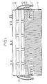
- Figure 1 is a side view of a lead-acid battery;
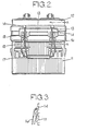
- Figure 2 is an end view of the battery; and
- Figure 3 is a sectional view taken along the line A-A in Figure 2.
- Referring to the drawings, the lead-acid battery shown is for use in earth-moving equipment and includes a moulded rectangular battery box 11 housing the electrochemically active elements of the battery and a rectangular
moulded lid 12 secured to and closing the box 11. Conveniently the box and lid are each moulded in a hard rubber material. Formed integrally along each of the end walls of the box 11 is an elongated projectinglug 13 which is provided adjacent its opposite ends with respective through-holes 14 which extend between the upper and lower surfaces of the lug generally parallel with the respective end wall of the box 11. Supported between the pair ofapertures 14 in eachlug 13 is arespective carrying handle 15. - Each
handle 15 includes a single strip of braidedpolypropylene rope 16 which has been passed through itsrespective apertures 14 and joined at its ends to define a continuous loop. Moreover, each strip ofrope 16 is passed twice through asynthetic resin sleeve 17, which is arranged to be relatively rigid compared with therope 16. In use, when it is required to lift the battery, thehandles 15 are gripped by way of thesleeves 17, whereby the force required to lift the battery is applied to thelugs 13 by way of the double thicknesses of rope defining the handles. In this way, usingstandard thickness lugs 13 without reinforcement, it is found that the battery can readily be lifted without any adverse affect on the lugs. The reason for this result is believed to be that the double thicknesses of rope spread the lifing force more evenly over thelugs 13. - In one practical example, using a moulded hard rubber battery box 11 in which the lugs had a depth of about 19 mm, each
hole 14 had a diameter of about 7 mm and was spaced by about 7 mm from the outer edge of the lug, the lugs showed no adverse affect when tested with a 90 Kg load applied in any direction. By way of contrast, using conventional knotted rope handles, it was found that the lugs cracked when subjected to a load of only 51 Kg. - Conveniently, each
rope 15 is joined at its ends to define the required loopedhandles 16 by moulding ashort connector member 18 in an acid-resistant synthetic resin material, such as polypropylene, around the ends of the rope. However, as an alternative to the example described above, moulding the acid-resistant synthetic resin material around the ends of each rope could serve not only to join the ends of the rope but also to produce a handle grip surrounding part of the portions of the rope extending between the associatedholes 14. In this case the handle grip would replace thesleeve 17. As a further alternative to the example described above, the lugs could be provided on thebattery lid 12, although this arrangement is not preferred since of course lifting the battery then applies a force tending to rupture the join between the lid-12 and the box 11. - Although in the above example, polyproylene rope has been used as the material of the
handles 15, it is to be appreciated that other acid-resistant rope materials, such as polyethylene terephthalate could have been used. In addition, acid-resistant elongated flexible materials other than rope could have been used for thehandles 15, such as a single filament of polypropylene, but rope is preferred because of its strength and low stretchability.
Claims (9)
Applications Claiming Priority (2)
| Application Number | Priority Date | Filing Date | Title |
|---|---|---|---|
| GB7935626 | 1979-10-13 | ||
| GB7935626 | 1979-10-13 |
Publications (2)
| Publication Number | Publication Date |
|---|---|
| EP0036878A1 EP0036878A1 (en) | 1981-10-07 |
| EP0036878B1 true EP0036878B1 (en) | 1985-08-28 |
Family
ID=10508500
Family Applications (1)
| Application Number | Title | Priority Date | Filing Date |
|---|---|---|---|
| EP80901924A Expired EP0036878B1 (en) | 1979-10-13 | 1981-04-21 | An electric storage battery |
Country Status (9)
| Country | Link |
|---|---|
| US (1) | US4374188A (en) |
| EP (1) | EP0036878B1 (en) |
| JP (1) | JPS56501343A (en) |
| BR (1) | BR8008854A (en) |
| DE (1) | DE3071037D1 (en) |
| GB (1) | GB2071400B (en) |
| IE (1) | IE50255B1 (en) |
| WO (1) | WO1981001074A1 (en) |
| ZA (1) | ZA806276B (en) |
Families Citing this family (13)
| Publication number | Priority date | Publication date | Assignee | Title |
|---|---|---|---|---|
| US4791702A (en) * | 1988-02-29 | 1988-12-20 | General Motors Corporation | Carrying handle |
| EP0355854A1 (en) * | 1988-08-26 | 1990-02-28 | KUNSTSTOFFWERK THERMOPLAST N. & R. BAWART | Carrying cord with a carrying handle |
| US4862554A (en) * | 1988-11-04 | 1989-09-05 | Chojnacki Daniel M | Safstrap |
| GB2265250A (en) * | 1992-03-12 | 1993-09-22 | Tungstone Batteries Ltd | Carrying handle for automotive battery |
| US5372899A (en) * | 1994-03-16 | 1994-12-13 | At&T Corp. | Battery handle |
| US5565283A (en) * | 1995-05-19 | 1996-10-15 | Lucent Technologies Inc. | Battery Handle |
| US6177211B1 (en) | 1998-11-20 | 2001-01-23 | Gnb Technologies, Inc. | Detachable rope battery handle assembly |
| US6187474B1 (en) * | 1999-02-03 | 2001-02-13 | Lucent Technologies Inc. | Battery container |
| US6428927B2 (en) | 1999-12-02 | 2002-08-06 | Gnb Technologies, Inc. | Detachable rope handle assembly for a battery |
| US6484364B2 (en) * | 2000-04-19 | 2002-11-26 | Raytheon Company | Lifting assembly |
| US20040188484A1 (en) * | 2003-03-28 | 2004-09-30 | Glenn Seale | Strap and method for utilizing the strap |
| US8263257B2 (en) * | 2008-06-03 | 2012-09-11 | C&D Technologies, Inc. | Removable handle for industrial battery |
| KR20190049750A (en) * | 2016-09-12 | 2019-05-09 | 리튬 웍스 테크놀로지 비브이 | How to handle rechargeable battery modules and rechargeable battery modules |
Family Cites Families (11)
| Publication number | Priority date | Publication date | Assignee | Title |
|---|---|---|---|---|
| US971876A (en) * | 1908-12-21 | 1910-10-04 | Vincent G Apple | Battery-carrier. |
| GB191012839A (en) * | 1910-05-26 | 1911-04-27 | Max Landsberg | Improved Construction of Device for Suspending Bags, Pendants, Lockets, and other Articles. |
| GB869329A (en) * | 1958-12-24 | 1961-05-31 | Bosch Gmbh Robert | Improvements in or relating to batteries |
| DE1190530B (en) * | 1960-11-25 | 1965-04-08 | Varta Ag | Handle and carrying device for the container of electrical accumulators |
| US3269495A (en) * | 1965-04-26 | 1966-08-30 | Philadelphia Handle Company In | Plastic heat-sealed luggage handle with handgrip and end loops |
| DE7027937U (en) * | 1970-07-24 | 1971-12-30 | Bosch Gmbh Robert | LEAD ACCUMULATOR WITH CASE AND LID MADE OF THERMOPLASTIC PLASTIC. |
| US3845542A (en) * | 1972-10-05 | 1974-11-05 | Gould Inc | Method of attaching a rope handle to a thin-walled battery |
| GB1453977A (en) * | 1973-03-14 | 1976-10-27 | Chloride Lorival Ltd | Electric storage battery handels |
| DE7538942U (en) * | 1975-12-06 | 1977-05-18 | Varta Batterie Ag, 3000 Hannover | ACCUMULATOR HOUSING WITH FORMED HANDLE BAR |
| DE2716293C3 (en) * | 1977-04-13 | 1980-10-23 | Varta Batterie Ag, 3000 Hannover | Carrying cord for electric accumulators and device for their manufacture |
| ES229473Y (en) * | 1977-06-22 | 1977-12-16 | HANDLE FOR ELECTRIC ACCUMULATORS. |
-
1980
- 1980-10-13 JP JP50230580A patent/JPS56501343A/ja active Pending
- 1980-10-13 WO PCT/GB1980/000163 patent/WO1981001074A1/en active IP Right Grant
- 1980-10-13 GB GB8113389A patent/GB2071400B/en not_active Expired
- 1980-10-13 BR BR8008854A patent/BR8008854A/en unknown
- 1980-10-13 DE DE8080901924T patent/DE3071037D1/en not_active Expired
- 1980-10-13 ZA ZA00806276A patent/ZA806276B/en unknown
- 1980-10-13 US US06/276,383 patent/US4374188A/en not_active Expired - Lifetime
- 1980-10-13 IE IE2120/80A patent/IE50255B1/en unknown
-
1981
- 1981-04-21 EP EP80901924A patent/EP0036878B1/en not_active Expired
Also Published As
| Publication number | Publication date |
|---|---|
| DE3071037D1 (en) | 1985-10-03 |
| US4374188A (en) | 1983-02-15 |
| IE50255B1 (en) | 1986-03-05 |
| WO1981001074A1 (en) | 1981-04-16 |
| EP0036878A1 (en) | 1981-10-07 |
| GB2071400A (en) | 1981-09-16 |
| ZA806276B (en) | 1981-10-28 |
| BR8008854A (en) | 1981-09-01 |
| JPS56501343A (en) | 1981-09-17 |
| IE802120L (en) | 1981-04-13 |
| GB2071400B (en) | 1984-07-11 |
Similar Documents
| Publication | Publication Date | Title |
|---|---|---|
| EP0036878B1 (en) | An electric storage battery | |
| US20120085774A1 (en) | One-piece container handle | |
| US10446808B2 (en) | Systems and methods for a flexible battery handle assembly for lead-acid batteries | |
| US4231605A (en) | Carrier assembly for multi-pack containers | |
| US971876A (en) | Battery-carrier. | |
| US2461030A (en) | Method of making torpedo nets | |
| US3557998A (en) | Wide mouth container and closure having integral opening means | |
| US8857641B1 (en) | Manipulating and restraining a two piece septic tank | |
| US1982801A (en) | Interchangeable battery cell | |
| EP0042257A1 (en) | Ratchet buckle | |
| US5111952A (en) | Lid with a handle for containers of accumulators | |
| US3797876A (en) | Battery carrying arrangement | |
| US1908926A (en) | Lifting device | |
| EP0518486A1 (en) | Hauling sheave with cleats | |
| US2436554A (en) | Pallet | |
| DE102014102996A1 (en) | Traction battery with lifting lugs | |
| JP2504535Y2 (en) | Waste container | |
| US2775476A (en) | Self-tightening and gripping battery lifter | |
| CN220465351U (en) | Manual locking device | |
| CN217358254U (en) | Slingshot with pulley | |
| CN213706364U (en) | Packing carton with dustproof hand is detained | |
| US1455020A (en) | Grapple | |
| CN211513232U (en) | Hosepipe case and fire engine | |
| US3226148A (en) | Battery carrier | |
| CN210203658U (en) | Portable belt type travelling basket |
Legal Events
| Date | Code | Title | Description |
|---|---|---|---|
| PUAI | Public reference made under article 153(3) epc to a published international application that has entered the european phase |
Free format text: ORIGINAL CODE: 0009012 |
|
| 17P | Request for examination filed |
Effective date: 19810501 |
|
| AK | Designated contracting states |
Designated state(s): DE FR |
|
| RAP1 | Party data changed (applicant data changed or rights of an application transferred) |
Owner name: LUCAS INDUSTRIES PLC |
|
| GRAA | (expected) grant |
Free format text: ORIGINAL CODE: 0009210 |
|
| AK | Designated contracting states |
Designated state(s): DE FR |
|
| REF | Corresponds to: |
Ref document number: 3071037 Country of ref document: DE Date of ref document: 19851003 |
|
| ET | Fr: translation filed | ||
| PLBE | No opposition filed within time limit |
Free format text: ORIGINAL CODE: 0009261 |
|
| STAA | Information on the status of an ep patent application or granted ep patent |
Free format text: STATUS: NO OPPOSITION FILED WITHIN TIME LIMIT |
|
| 26N | No opposition filed | ||
| PGFP | Annual fee paid to national office [announced via postgrant information from national office to epo] |
Ref country code: FR Payment date: 19891010 Year of fee payment: 10 |
|
| PGFP | Annual fee paid to national office [announced via postgrant information from national office to epo] |
Ref country code: DE Payment date: 19891130 Year of fee payment: 10 |
|
| PG25 | Lapsed in a contracting state [announced via postgrant information from national office to epo] |
Ref country code: FR Effective date: 19910628 |
|
| PG25 | Lapsed in a contracting state [announced via postgrant information from national office to epo] |
Ref country code: DE Effective date: 19910702 |
|
| REG | Reference to a national code |
Ref country code: FR Ref legal event code: ST |