EP0036803B1 - Appareil de contrôle de positionnement - Google Patents
Appareil de contrôle de positionnement Download PDFInfo
- Publication number
- EP0036803B1 EP0036803B1 EP81400385A EP81400385A EP0036803B1 EP 0036803 B1 EP0036803 B1 EP 0036803B1 EP 81400385 A EP81400385 A EP 81400385A EP 81400385 A EP81400385 A EP 81400385A EP 0036803 B1 EP0036803 B1 EP 0036803B1
- Authority
- EP
- European Patent Office
- Prior art keywords
- mirror
- plane
- pilot
- point
- semi
- Prior art date
- Legal status (The legal status is an assumption and is not a legal conclusion. Google has not performed a legal analysis and makes no representation as to the accuracy of the status listed.)
- Expired
Links
Images

Classifications
-
- G—PHYSICS
- G08—SIGNALLING
- G08G—TRAFFIC CONTROL SYSTEMS
- G08G5/00—Traffic control systems for aircraft
- G08G5/20—Arrangements for acquiring, generating, sharing or displaying traffic information
- G08G5/22—Arrangements for acquiring, generating, sharing or displaying traffic information located on the ground
-
- G—PHYSICS
- G01—MEASURING; TESTING
- G01C—MEASURING DISTANCES, LEVELS OR BEARINGS; SURVEYING; NAVIGATION; GYROSCOPIC INSTRUMENTS; PHOTOGRAMMETRY OR VIDEOGRAMMETRY
- G01C3/00—Measuring distances in line of sight; Optical rangefinders
-
- G—PHYSICS
- G08—SIGNALLING
- G08G—TRAFFIC CONTROL SYSTEMS
- G08G5/00—Traffic control systems for aircraft
- G08G5/50—Navigation or guidance aids
- G08G5/51—Navigation or guidance aids for control when on the ground, e.g. taxiing or rolling
Definitions
- the subject of the invention is an apparatus for controlling the positioning of an aircraft in a plane at a parking point P situated at a distance (d) from a fixed reference point 0 along an approach line passing through P and O.
- the invention applies especially to the positioning of an aircraft on a parking area.
- the line of approach is a straight line passing through the parking point (P) and through a location point (O), and which can be materialized either on the ground, or by the alignment of two spaced apart one another, for example lights.
- the pilot remains on this line while observing the alignment and stops when a second alignment indicates that he has arrived at the parking point. Therefore, the pilot has to look in two directions, which is quite annoying.
- the two alignments are marked by marks which normally cannot be very far from each other and therefore the alignment giving the parking position makes a fairly small angle with the line of approach. As a result, an error in the pilot's appreciation can result in a fairly large deviation from the fixed parking position (P) (US-A-3,674,226 and 3,775,741
- the line of approach is materialized by mirror in which the pilot observes the images of several reference points placed on the plane and spaced apart longitudinally. The distance positioning is obtained by electrical contacts incorporated in the parking area and actuating a signal placed next to the mirror.
- Such electrical contacts can be subject to breakdowns and, in addition, such a device can only be suitable for a single type of device unless the parking area is equipped with several contacts positioned according to the dimensions of each. aircraft type.
- the subject of the invention is a purely optical device which, without being excessively bulky or expensive, allows the pilot to position his device without having to turn his head to check the distance.
- the device according to the invention makes it possible to easily modify the stopping distance to adapt to different types of aircraft.
- the control device comprises an optical reflection device placed on the approach line and forming in the pilot's eye the image of a landmark placed on the aircraft, paired characterized by a semi-transparent glass whose center is a fixed reference point 0 interposed on the path of the light rays going from the pilot's eye to the reflection device and making an angle of 45 ° with the vertical plane passing through the line of approach and a plane mirror forming in the pilot's eye a second image of the reference point of the aircraft after reflection of the light rays on said plane mirror, the semi-transparent glass and the reflection device, the plane mirror making with the semi-transparent glass an angle A such that the two images of the reference point are confused when the reference point is vertical to the parking point P.
- the plane mirror is mounted orientable around an axis perpendicular to the plane of movement of the pilot and is associated with an orientation device allowing, by varying the angle A to adjust the distance (d) from the parking point. P at location point O.
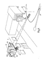
- FIG. 1 a terminal satellite 1 is shown schematically with which an airplane 2 is to be positioned.
- the aircraft approaches the parking point while staying along an approach line marked, for example, by a target.
- the control device consists of an optical assembly 3, which is placed on the satellite 1 and the operation of which is shown diagrammatically in FIGS. 2, 3 and 4.
- the device consists of two mirrors 31, 32 and a semi-transparent lens 33.
- the center of the lens 33 serves as a reference point 0 because it is compared to it that distance measurements are made.
- the parking point P is placed at a distance (d) from the point O.
- the test pattern 11 materializes the line of approach which is situated in the vertical plane passing through the points 0 and P.
- the mirror 31 in the case of FIGS. 2 and 3 is perpendicular to the straight line OP. Consequently, it reflects back on themselves the rays coming from the eye of the observer and having passed through the semi-transparent glass 33 which forms an angle of 45 ° with the line PO and consequently with the mirror 31.
- the mirror 32 makes an angle A with the glass 33.
- This system gives an observer moving along the axis xx 'passing through the points P and 0 and perpendicular to the mirror 31 two images of himself whose apparent deviation is a function of the distance from the observer to the mirror 31
- the first of these two images is given by the mirror 31, the second being the result of the three reflections on the mirror 32, the semi-transparent glass 33 and the mirror 31.
- the angle A is chosen so that the two images appear to be confused for the observer located at point P.
- the rays meeting the ice 33 at point 0, ie directly along the line x'x or after reflection on the mirror 32 make an angle 2A between them.
- Such a system therefore informs the observer both of the distance to the point P by the appreciation of the difference between the two images and of the speed of approach to this same point P by the appreciation of the speed of variation of this gap.
- the positioning can be done with great precision if the pilot takes care to make the images of particular points coincide, for example a flashing light 21 placed on the airplane.
- a colored filter 34 on the path between the point 0 of the glass 33 and the point I of incidence on the mirror 32
- other known systems can be used for this purpose. For example, it is possible to tilt the mirror 32 by tilting it slightly relative to the vertical. Thus, we give a slight offset in height between the two images given by the system and it is easier to align the two images than to realize their coincidence.
- the pilot can observe himself or choose a reference point 21 on the plane, which he will place vertically over the parking point P.
- FIG. 4 another arrangement of the mirror 31 has been shown which, in this case, is parallel to the line of approach PO.
- the bearing is in fact that the mirror 31 returns on themselves the rays having encountered the semi-transparent glass 33 at point 0, and it is sufficient for this that they make an angle of 45 ° with the reflecting face of the glass 33 which, in this case, is crossed without reflection by the rays meeting the mirror 32.
- the device can also be used in general, to guide the pilot following a straight path. It suffices to draw a reference mark on the mirror 31 in the vertical plane passing through the line of approach PO. The pilot then aligns the image given by the mirror with this mark while observing the distance between the two images given by the system.
- the device has been developed positioning aircraft on parking lots, it is obvious that it could also be used in other applications and, in general, whenever it is necessary to place a moving object is at a determined point along a determined approach line.
Landscapes
- Physics & Mathematics (AREA)
- Engineering & Computer Science (AREA)
- General Physics & Mathematics (AREA)
- Aviation & Aerospace Engineering (AREA)
- Electromagnetism (AREA)
- Radar, Positioning & Navigation (AREA)
- Remote Sensing (AREA)
- Navigation (AREA)
- Vehicle Body Suspensions (AREA)
- Paper (AREA)
- Traffic Control Systems (AREA)
- Optical Radar Systems And Details Thereof (AREA)
- Making Paper Articles (AREA)
- Supply Devices, Intensifiers, Converters, And Telemotors (AREA)
- Auxiliary Devices For And Details Of Packaging Control (AREA)
- Control Of Position Or Direction (AREA)
- Optical Elements Other Than Lenses (AREA)
- Length Measuring Devices By Optical Means (AREA)
- Apparatus For Radiation Diagnosis (AREA)
Priority Applications (1)
| Application Number | Priority Date | Filing Date | Title |
|---|---|---|---|
| AT81400385T ATE10138T1 (de) | 1980-03-19 | 1981-03-13 | Vorrichtung zum ermitteln der lage. |
Applications Claiming Priority (2)
| Application Number | Priority Date | Filing Date | Title |
|---|---|---|---|
| FR8006127A FR2478825A1 (fr) | 1980-03-19 | 1980-03-19 | Etage de selection du signal alternatif de plus grande amplitude parmi deux signaux de frequences differentes |
| FR8006127 | 1980-03-19 |
Publications (2)
| Publication Number | Publication Date |
|---|---|
| EP0036803A1 EP0036803A1 (fr) | 1981-09-30 |
| EP0036803B1 true EP0036803B1 (fr) | 1984-10-31 |
Family
ID=9239840
Family Applications (1)
| Application Number | Title | Priority Date | Filing Date |
|---|---|---|---|
| EP81400385A Expired EP0036803B1 (fr) | 1980-03-19 | 1981-03-13 | Appareil de contrôle de positionnement |
Country Status (8)
| Country | Link |
|---|---|
| US (1) | US4405204A (cg-RX-API-DMAC7.html) |
| EP (1) | EP0036803B1 (cg-RX-API-DMAC7.html) |
| JP (1) | JPS57717A (cg-RX-API-DMAC7.html) |
| AT (1) | ATE10138T1 (cg-RX-API-DMAC7.html) |
| DE (1) | DE3166894D1 (cg-RX-API-DMAC7.html) |
| DK (1) | DK119581A (cg-RX-API-DMAC7.html) |
| FR (1) | FR2478825A1 (cg-RX-API-DMAC7.html) |
| NO (1) | NO810924L (cg-RX-API-DMAC7.html) |
Families Citing this family (3)
| Publication number | Priority date | Publication date | Assignee | Title |
|---|---|---|---|---|
| US4612871A (en) * | 1985-01-02 | 1986-09-23 | Tachikawa Spring Co., Ltd. | Device for visually setting the spring force of a seat suspension for a vehicle |
| US5285205A (en) * | 1990-07-16 | 1994-02-08 | White Bernard H | Laser guided vehicle positioning system and method |
| DE4406821A1 (de) * | 1994-03-02 | 1995-09-07 | Hipp Johann | Vorrichtung zur Führung des Piloten eines sich seiner Parkposition nähernden Flugzeuges |
Family Cites Families (8)
| Publication number | Priority date | Publication date | Assignee | Title |
|---|---|---|---|---|
| US3149196A (en) * | 1960-03-02 | 1964-09-15 | Roth Alexander | Vehicular guidance systems |
| US3530388A (en) * | 1965-04-21 | 1970-09-22 | Westinghouse Electric Corp | Light amplifier system |
| US3663105A (en) * | 1967-06-28 | 1972-05-16 | Alton D Anderson | Method and apparatus for measuring range utilizing superimposition or alignment of images |
| US3674226A (en) * | 1970-04-06 | 1972-07-04 | Federal Sign And Signal Corp | Aircraft parking method and means |
| US3775741A (en) * | 1970-10-16 | 1973-11-27 | Sperry Rand Corp | Aircraft parking system |
| US3690599A (en) * | 1971-03-11 | 1972-09-12 | Ira Vincent Hager | Aircraft docking guide |
| US3729262A (en) * | 1971-07-20 | 1973-04-24 | Burroughs Corp | Optical lens docking system |
| US3873210A (en) * | 1974-03-28 | 1975-03-25 | Burroughs Corp | Optical device for vehicular docking |
-
1980
- 1980-03-19 FR FR8006127A patent/FR2478825A1/fr active Granted
-
1981
- 1981-03-11 US US06/242,762 patent/US4405204A/en not_active Expired - Fee Related
- 1981-03-13 EP EP81400385A patent/EP0036803B1/fr not_active Expired
- 1981-03-13 AT AT81400385T patent/ATE10138T1/de not_active IP Right Cessation
- 1981-03-13 DE DE8181400385T patent/DE3166894D1/de not_active Expired
- 1981-03-17 DK DK119581A patent/DK119581A/da not_active Application Discontinuation
- 1981-03-18 JP JP3929281A patent/JPS57717A/ja active Pending
- 1981-03-18 NO NO810924A patent/NO810924L/no unknown
Also Published As
| Publication number | Publication date |
|---|---|
| EP0036803A1 (fr) | 1981-09-30 |
| US4405204A (en) | 1983-09-20 |
| DE3166894D1 (en) | 1984-12-06 |
| ATE10138T1 (de) | 1984-11-15 |
| NO810924L (no) | 1981-09-21 |
| DK119581A (da) | 1981-09-20 |
| FR2478825A1 (fr) | 1981-09-25 |
| JPS57717A (en) | 1982-01-05 |
| FR2478825B1 (cg-RX-API-DMAC7.html) | 1982-05-21 |
Similar Documents
| Publication | Publication Date | Title |
|---|---|---|
| EP0989386A1 (fr) | Dispositif d'aide à l'atterrissage, notamment pour l'inhibition d'alerte anti-collision sol | |
| EP2078183B1 (fr) | Dispositif optoélectronique d'aide au guidage et au roulage sur piste pour aéronef comportant une symbologie dédiée | |
| FR2712251A1 (fr) | Procédé et dispositif d'aide au pilotage d'un aéronef. | |
| CH373647A (fr) | Utilisation d'un dispositif indicateur visuel dans une cabine de pilotage d'un avion | |
| CA2372297C (fr) | Dispositif pour determiner les valeurs d'au moins un parametre de particules, notamment de gouttelettes d'eau | |
| FR2783500A1 (fr) | Dispositif d'aide au pilotage d'un aeronef, notamment a voilure tournante et en particulier un helicoptere | |
| CA2870403A1 (fr) | Systeme optique d'eclairage pour aeronef | |
| WO2007006762A2 (fr) | Dispositif optoelectronique d'aide au roulage pour aeronef comportant une symbologie dediee | |
| CA2173921C (fr) | Dispositif optoelectronique d'aide au pilotage d'un aeronef par mauvaise visibilite | |
| CA2160759C (fr) | Dispositif optoelectronique d'aide au pilotage d'un aeronef | |
| EP0036803B1 (fr) | Appareil de contrôle de positionnement | |
| FR2981148A1 (fr) | Equipement de mesure pour le controle d'un indicateur de trajectoire d'approche pour l'atterrissage d'un avion, et dispositif de controle correspondant. | |
| FR2841977A1 (fr) | Procede d'aide a la navigation d'un areonef et dispositif correspondant | |
| FR2724013A1 (fr) | Systeme de reperage d'orientation d'un instrument d'observation. | |
| FR2705293A1 (fr) | Système d'aide à la vision dans un véhicule automobile. | |
| EP0210088A1 (fr) | Appareil de visualisation à champ étendu dans lequel l'image est formée par la juxtaposition d'au moins deux images partielles | |
| EP0425365B1 (fr) | Dispositif optique de correction des défauts introduits par un hublot sphérique utilisé hors d'axe | |
| EP0321342A1 (fr) | Dispositif inertiel de stabilisation en inclinaison d'un élément orientable et miroir de télescope embarqué muni d'un tel dispositif | |
| EP3667366B1 (fr) | Procede et dispositif d'aide a l'atterrissage d'un aeronef pour aligner ledit aeronef sur une piste d'atterrissage | |
| EP0807876B1 (fr) | Dispositif de guidage d'un missile | |
| FR2668614A1 (fr) | Dispositif de visee compact a grand debattement angulaire pour equipement optronique de localisation et d'acquisition de cible. | |
| EP2700985B1 (fr) | Viseur tête haute compact | |
| EP0083268B1 (fr) | Procédé de réglage automatique de la netteté d'images projetées sur un écran et dispositifs pour la mise en oeuvre dudit procédé | |
| FR3089955A1 (fr) | Procede et systeme de guidage d’aide au suivi d’une trajectoire pour un pilotage au vecteur-vitesse d’un aeronef | |
| FR2468925A1 (fr) | Microscope a superposition d'images |
Legal Events
| Date | Code | Title | Description |
|---|---|---|---|
| PUAI | Public reference made under article 153(3) epc to a published international application that has entered the european phase |
Free format text: ORIGINAL CODE: 0009012 |
|
| AK | Designated contracting states |
Designated state(s): AT BE CH DE GB IT LU NL SE |
|
| 17P | Request for examination filed |
Effective date: 19811028 |
|
| ITF | It: translation for a ep patent filed | ||
| GRAA | (expected) grant |
Free format text: ORIGINAL CODE: 0009210 |
|
| AK | Designated contracting states |
Designated state(s): AT BE CH DE GB IT LI LU NL SE |
|
| REF | Corresponds to: |
Ref document number: 10138 Country of ref document: AT Date of ref document: 19841115 Kind code of ref document: T |
|
| REF | Corresponds to: |
Ref document number: 3166894 Country of ref document: DE Date of ref document: 19841206 |
|
| PG25 | Lapsed in a contracting state [announced via postgrant information from national office to epo] |
Ref country code: AT Effective date: 19850313 |
|
| PG25 | Lapsed in a contracting state [announced via postgrant information from national office to epo] |
Ref country code: SE Effective date: 19850314 |
|
| PG25 | Lapsed in a contracting state [announced via postgrant information from national office to epo] |
Ref country code: LU Free format text: LAPSE BECAUSE OF NON-PAYMENT OF DUE FEES Effective date: 19850331 Ref country code: LI Effective date: 19850331 Ref country code: CH Effective date: 19850331 Ref country code: BE Effective date: 19850331 |
|
| PLBE | No opposition filed within time limit |
Free format text: ORIGINAL CODE: 0009261 |
|
| STAA | Information on the status of an ep patent application or granted ep patent |
Free format text: STATUS: NO OPPOSITION FILED WITHIN TIME LIMIT |
|
| BERE | Be: lapsed |
Owner name: SOC. D'OPTIQUE PRECISION ELECTRONIQUE ET MECANIQUE Effective date: 19850313 |
|
| PG25 | Lapsed in a contracting state [announced via postgrant information from national office to epo] |
Ref country code: NL Effective date: 19851001 |
|
| GBPC | Gb: european patent ceased through non-payment of renewal fee | ||
| 26N | No opposition filed | ||
| REG | Reference to a national code |
Ref country code: CH Ref legal event code: PL |
|
| PG25 | Lapsed in a contracting state [announced via postgrant information from national office to epo] |
Ref country code: DE Effective date: 19851203 |
|
| NLV4 | Nl: lapsed or anulled due to non-payment of the annual fee | ||
| PG25 | Lapsed in a contracting state [announced via postgrant information from national office to epo] |
Ref country code: GB Effective date: 19881118 |
|
| EUG | Se: european patent has lapsed |
Ref document number: 81400385.1 Effective date: 19860128 |