EP0036799A1 - Zelle zur kontinuierlichen Überwachung von Tritium im Wasser unter Anwendung von Szintillationskugeln aus dotiertem Quarz - Google Patents
Zelle zur kontinuierlichen Überwachung von Tritium im Wasser unter Anwendung von Szintillationskugeln aus dotiertem Quarz Download PDFInfo
- Publication number
- EP0036799A1 EP0036799A1 EP19810400367 EP81400367A EP0036799A1 EP 0036799 A1 EP0036799 A1 EP 0036799A1 EP 19810400367 EP19810400367 EP 19810400367 EP 81400367 A EP81400367 A EP 81400367A EP 0036799 A1 EP0036799 A1 EP 0036799A1
- Authority
- EP
- European Patent Office
- Prior art keywords
- water
- cell
- photomultipliers
- quartz
- balls
- Prior art date
- Legal status (The legal status is an assumption and is not a legal conclusion. Google has not performed a legal analysis and makes no representation as to the accuracy of the status listed.)
- Granted
Links
Images

Classifications
-
- G—PHYSICS
- G01—MEASURING; TESTING
- G01T—MEASUREMENT OF NUCLEAR OR X-RADIATION
- G01T1/00—Measuring X-radiation, gamma radiation, corpuscular radiation, or cosmic radiation
- G01T1/003—Scintillation (flow) cells
-
- G—PHYSICS
- G01—MEASURING; TESTING
- G01T—MEASUREMENT OF NUCLEAR OR X-RADIATION
- G01T7/00—Details of radiation-measuring instruments
- G01T7/02—Collecting means for receiving or storing samples to be investigated and possibly directly transporting the samples to the measuring arrangement; particularly for investigating radioactive fluids
Definitions
- the invention relates to a measuring cell for continuous monitoring of the concentration of tritium in water by detecting its ⁇ radiation with a measurement sensitivity lower than the "maximum admissible concentration" of tritium in water for the population. (CMAp).
- the monitoring device comprises a measuring cell formed by a cylindrical chamber containing a large number of scintillating balls of small diameter and in which the water to be checked circulates.
- the device according to the invention uses scintillating balls and quartz windows which, by their high efficiency, make it possible to measure less than from CMAp to tritium.
- the scintillator beads are quartz beads with a diameter of less than 1 mm.
- the wall of the chamber comprises, on the side of the water supply, a groove extending over an angle slightly less than 180 °, so as to distribute the liquid uniformly inside the volume occupied by the balls.
- This arrangement avoids the formation of preferential paths in the room. In this way, the contaminated fluid circulates around the maximum of balls to achieve the largest possible contact surface.
- Two photomultipliers located on either side of the cell detect the photons emitted and deliver a signal in the form of electrical pulses. These pulses, after amplification, discrimination of the background noise, summation and coincidence are separated according to two energy classes: one below a discrimination threshold adjustable according to the radioelements present in the water, accounts for most of the pulses due to the radiation 5 of tritium; the other class of ener gie, greater than the discrimination threshold, adds up the other pulses.
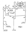
- FIG 1 a schematic view of the monitoring device according to the invention.
- the measurement cell has been designated by reference 2.
- This cell 2 is connected to a hydraulic circuit ensuring the circulation of the water therein.
- This hydraulic circuit includes two solenoid valves 4 and 6 for selecting the sample.
- the solenoid valve 4 is connected to the circuit to be monitored. It is open during normal operation of the monitoring device.
- the solenoid valve 6 is used for the calibration of the measuring device.
- the sampling circuit is connected to a tritiated water tank of known activity.
- the water for which it is desired to monitor the tritium concentration is brought through a pipe 8 to a pump 10, for example a gear pump.
- the hydraulic circuit also includes two valves 12 and 14 with manual control which make it possible to adjust the flow rate by means of the bypass 13, a pressure gauge 16 for controlling the pressure at the outlet of the pump, and a pressure gauge 17 for controlling the clogging of the filtering device, a filtration assembly comprising a prefilter 18, with a membrane with a porosity of 0.5, a deferiser filter 20, and a silver ion filter 22.
- a pipe 24 brings the filtered water up to the measuring cell 2.
- a buffer volume 26 with venting, connected to the circuit by the solenoid valve 28, is used for expansion of the circuit and makes it possible to empty the cell 2 by siphoning.
- a flow meter 30 makes it possible to measure the instantaneous flow rate of cell 2. This flow meter is provided with a minimum flow fault contact which closes when the water flow rate drops below a given value.
- a flow meter 32 totals the amount of water passed through the measuring cell.
- the hydraulic circuit comprises two circuit return solenoid valves 34 and 36, and two drain valves 38 and -40.
- FIG. 2 shows a detailed view of the measuring cell 2. It comprises a basket 42, of parallelepiped external shape, which delimits a cylindrical chamber 44.
- Two automatic connectors 46 and 48 connected to the hydraulic circuit ensure the circulation of the water whose tritium concentration is to be measured inside the cell 2.
- the fluid enters via the connector 46, and its outlet via the connector 48.
- the circulation is thus bottom to top, which prevents any trapping of air bubbles.
- the seal between fittings 46 and 48 and the rest of the circuit is ensured by O-rings (not shown).
- the chamber 44 is closed by two portholes 54 in doped quartz.
- the chamber 44 contains scintillating balls 56.
- the diameter of these balls is less than 1 mm. They occupy a volume of 60 cm.
- These beads are made of quartz, doped with cerium, and containing traces of titanium and alumina.
- This material is an excellent scintillator sensitive to low energy f3 rays like those of tritium.
- the sensitivity is thus at least 10 times higher than that obtained with plastic balls.
- the quartz beads can be easily regenerated by cleaning. Indeed, the chemical inertness of this material allows the use of concentrated acids which are effective cleaning agents.
- the mesh of the grids 50 and 52 is 16 ⁇ .
- this angle is 150 °.
- Tests by injecting a dye into water upstream of the cell made it possible to measure the uniformity of the coloration over the entire surface.
- the uniform coloring time of the basket is 6 seconds for a flow rate of 20 1 / h. This staining time of 6 seconds thus represents the response time of the cell.
- Two photomultipliers 64 with quartz windows and low background noise are located on either side of cell 2 against the doped quartz portholes 54.
- Lead protection against external ambient radiation surrounds the cell and the two photomultipliers and is in the form of two semi-spherical shells 65 surrounding the basket 42 and extended by two cylinders enveloping the photomultipliers. These protections are mounted on two cylindrical bars by means of sliding sleeves.
- the cell is accessed by separating the two shells 65.
- the control of these shells is carried out using a hand wheel controlled manually. This protection also ensures the light-tightness of the scintillator and of the photomultipliers.
- Cell 2 has three operating modes: analysis, calibration and emptying.
- the analysis corresponds to the normal operation of the measuring cell.
- the hydraulic circuit is then connected directly by the solenoid valve 4 to the circuit to be monitored.
- the solenoid valves 4 and 34 are open, while the solenoid valves 6, 28, 36 are closed.
- the calibration makes it possible to control the sensitivity of the device by connecting it via the solenoid valve 6 to a tritiated water tank of known activity.
- the solenoid valves 6 and 36 are then open, while the solenoid valves 4, 28, 34 are closed.
- the emptying takes place after each calibration operation or before making a cell change. It consists in emptying all the hydraulic circuits.
- the solenoid valves 4, 6, 34 are closed and the solenoid valves 28 and 36 are open.
- the regulating valves 12 and 14 ensure, by virtue of the bypass 13 in cell 2, a flow rate of between 5 and 50 liters per hour while maintaining a constant sampling flow rate of approximately 80 l / h. This device makes it possible to reduce the response time caused by the dead volumes due to the sampling pipes, the length and diameter of which are significant.
- the measurement flow is fixed at 20 l / h.
- the pressure in the circuit is between 1 and 5 bar.
- the filters 18, 20 and 22 make it possible to avoid rapid chemical pollution of the scintillating balls 56, pollution which would result in a loss of sensitivity to the activity.
- a loss of sensitivity of the scintillator of only 10% was noted after a passage of 30 m 3 of water.
- the pressure gauge 17, the flow meter 30 and the flow meter 32 make it possible to control the clogging of the filters 18, 20 and 22 and thus to change the cartridges of these filters according to the quality of the sample water.
- the total volume of the hydraulic circuit is 6 1, including 3.8 1 for the filters.
- FIG. 4 shows a block diagram of the electronic part of the monitoring device according to the invention.
- the measuring chain is made up of the devices which receive the detector signal, which transform and amplify it.
- This chain comprises the scintillator constituted by the balls 56, the portholes 54 and the photomultipliers 64 arranged on each side of the cell 2.
- An amplifier-discriminator 66 provides the stabilized high voltage supply, the amplification and the discrimination of the noise of background of the signals from the two photomultipliers 64.
- the amplified signals from the amplifier 66 are introduced into a coincidence drawer 68.
- This circuit delivers an output signal of suitable amplitude only when two pulses have been applied simultaneously to the entry. It also makes it possible to separate the pulses from the photomultipliers 64 into two energy classes.
- the user can in fact set a discrimination threshold ST as a function of the nature of the radioelements whose presence in the water that is desired control is most likely.
- a first measurement channel known as the "tritium channel” accounts for pulses below the ST threshold, due essentially to the e rays of tritium, as well as to a more or less significant participation of other water contaminants.
- the other measurement channel called “global measurement channel” counts the other pulses above the discrimination threshold ST. These pulses are due in particular to other radioactive contaminants in water, to background noise of nuclear, cosmic origin or from ambient radiation therein, and to weak radiation from tritium.
- a two-position switch facilitates tests and adjustments by directing the pulses of channels V I and.V 2 to an output.
- the measurement chain also comprises two ictometer drawers 70, which indicate the average frequency of the pulses applied to them. These are two analog logarithmic ictometers. A galvanometer graduated in counts per second from 0.1 to 10 5 counts per second makes it possible to assess the counting rate of the chosen output. A recorder output is also available.
- a shaping drawer 72 ensures the shaping and the galvanic isolation of the pulses supplied by the coincidence drawer 68 and makes it possible to attack either counting scales or centralized and computerized organs.
- the tritium alarm was indicated, which is triggered when a predetermined threshold is exceeded.
- a service drawer 74 has decoupling relays which allow the measurement chain to be tested using an external pulse generator. This drawer servitude also makes it possible to ensure the proper functioning of the device. It signals in particular an insufficient flow of water in the measurement circuit, a faulty display of an electronic drawer and a bad position of the switch located on the front face of the tritium 68 coincidence drawer which allows to select the measurement channel.
- An electric plate 76 makes it possible to control the entire apparatus. In particular, it ensures the succession of the different operating phases: analysis, calibration and emptying. These operations, controlled by three pushbuttons located on the front of the device, can be followed on a functional block diagram.
Landscapes
- Physics & Mathematics (AREA)
- Health & Medical Sciences (AREA)
- Life Sciences & Earth Sciences (AREA)
- General Physics & Mathematics (AREA)
- High Energy & Nuclear Physics (AREA)
- Molecular Biology (AREA)
- Spectroscopy & Molecular Physics (AREA)
- Chemical & Material Sciences (AREA)
- Analytical Chemistry (AREA)
- Measurement Of Radiation (AREA)
Applications Claiming Priority (2)
| Application Number | Priority Date | Filing Date | Title |
|---|---|---|---|
| FR8005625 | 1980-03-13 | ||
| FR8005625A FR2478322A1 (fr) | 1980-03-13 | 1980-03-13 | Cellule de mesure pour la surveillance en continu de la concentration du tritium dans l'eau utilisant des billes scintillatrices en quartz dope |
Publications (2)
| Publication Number | Publication Date |
|---|---|
| EP0036799A1 true EP0036799A1 (de) | 1981-09-30 |
| EP0036799B1 EP0036799B1 (de) | 1985-01-30 |
Family
ID=9239633
Family Applications (1)
| Application Number | Title | Priority Date | Filing Date |
|---|---|---|---|
| EP19810400367 Expired EP0036799B1 (de) | 1980-03-13 | 1981-03-10 | Zelle zur kontinuierlichen Überwachung von Tritium im Wasser unter Anwendung von Szintillationskugeln aus dotiertem Quarz |
Country Status (4)
| Country | Link |
|---|---|
| EP (1) | EP0036799B1 (de) |
| CA (1) | CA1168767A (de) |
| DE (1) | DE3168567D1 (de) |
| FR (1) | FR2478322A1 (de) |
Cited By (4)
| Publication number | Priority date | Publication date | Assignee | Title |
|---|---|---|---|---|
| US5115559A (en) * | 1989-09-06 | 1992-05-26 | Matsushita Electric Industrial Co., Ltd. | Electronic component mounting apparatus |
| EP1306691A3 (de) * | 2001-10-23 | 2006-05-03 | Forschungszentrum Jülich Gmbh | Messzelle und Verfahren zur Messung der Beta-Aktivität einer radioaktiven Flüssigkeit |
| WO2006089991A1 (es) * | 2005-02-25 | 2006-08-31 | Universidad De Barcelona | Sensor radioquímico para fluidos |
| RU2461023C1 (ru) * | 2011-04-27 | 2012-09-10 | Открытое акционерное общество "Ведущий проектно-изыскательский и научно-исследовательский институт промышленной технологии" (ОАО "ВНИПИпромтехнологии") | Способ радиологического мониторинга загрязнения тритием недр месторождений углеводородов |
Citations (2)
| Publication number | Priority date | Publication date | Assignee | Title |
|---|---|---|---|---|
| DE1241001B (de) * | 1963-05-20 | 1967-05-24 | Akad Wissenschaften Ddr | Szintillatorkoerper und Verfahren zu seiner Herstellung |
| FR1538607A (fr) * | 1967-07-27 | 1968-09-06 | Commissariat Energie Atomique | Appareil de contrôle en continu de la radioactivité des liquides chargés |
-
1980
- 1980-03-13 FR FR8005625A patent/FR2478322A1/fr active Granted
-
1981
- 1981-03-10 DE DE8181400367T patent/DE3168567D1/de not_active Expired
- 1981-03-10 EP EP19810400367 patent/EP0036799B1/de not_active Expired
- 1981-03-11 CA CA000372803A patent/CA1168767A/fr not_active Expired
Patent Citations (2)
| Publication number | Priority date | Publication date | Assignee | Title |
|---|---|---|---|---|
| DE1241001B (de) * | 1963-05-20 | 1967-05-24 | Akad Wissenschaften Ddr | Szintillatorkoerper und Verfahren zu seiner Herstellung |
| FR1538607A (fr) * | 1967-07-27 | 1968-09-06 | Commissariat Energie Atomique | Appareil de contrôle en continu de la radioactivité des liquides chargés |
Non-Patent Citations (4)
| Title |
|---|
| E.D. BRANSOME: THE CURRENT STATUS OF LIQUID SCINTILLATION COUNTING" 1970, Grune & Stratton NEW YORK (US) Chapitre 8: E. SCHRAM: "Flow-monitoring of aqueous solutions containing weak béta-emitters" pages 95-109 * |
| IEEE TRANSACTIONS ON NUCLEAR SCIENCE, vol. NS-21, no. 1, février 1974 NEW YORK (US) A.N. SINGH et al.:"A sensitive detector system for the continuous monitoring of tritium in the air" pages 188-193 * |
| INSTRUMENTS AND EXPERIMENTAL TECHNIQUES, vol. 17, no. 1, partie 1, janvier-février 1974 WASHINGTON (US) T.N. SEREDENKO et al.:"Scintillation granules in the coincidence method" pages 59-62 * |
| NUCLEONICS, vol. 19, no. 7, juillet 1961 NEW YORK (US) "Scintillating Beads for Aqueous Solutions" page 82 * |
Cited By (7)
| Publication number | Priority date | Publication date | Assignee | Title |
|---|---|---|---|---|
| US5115559A (en) * | 1989-09-06 | 1992-05-26 | Matsushita Electric Industrial Co., Ltd. | Electronic component mounting apparatus |
| EP1306691A3 (de) * | 2001-10-23 | 2006-05-03 | Forschungszentrum Jülich Gmbh | Messzelle und Verfahren zur Messung der Beta-Aktivität einer radioaktiven Flüssigkeit |
| WO2006089991A1 (es) * | 2005-02-25 | 2006-08-31 | Universidad De Barcelona | Sensor radioquímico para fluidos |
| ES2258932A1 (es) * | 2005-02-25 | 2006-09-01 | Universidad De Barcelona | Sensor radioquimico para fluidos. |
| ES2258932B1 (es) * | 2005-02-25 | 2007-11-16 | Universidad De Barcelona | Sensor radioquimico para fluidos. |
| EP1860464A4 (de) * | 2005-02-25 | 2013-09-18 | Sanz Alex Tarancon | Radiochemischer sensor für fluide |
| RU2461023C1 (ru) * | 2011-04-27 | 2012-09-10 | Открытое акционерное общество "Ведущий проектно-изыскательский и научно-исследовательский институт промышленной технологии" (ОАО "ВНИПИпромтехнологии") | Способ радиологического мониторинга загрязнения тритием недр месторождений углеводородов |
Also Published As
| Publication number | Publication date |
|---|---|
| FR2478322A1 (fr) | 1981-09-18 |
| EP0036799B1 (de) | 1985-01-30 |
| CA1168767A (fr) | 1984-06-05 |
| DE3168567D1 (en) | 1985-03-14 |
| FR2478322B1 (de) | 1982-08-13 |
Similar Documents
| Publication | Publication Date | Title |
|---|---|---|
| KR101462189B1 (ko) | 방사능 자동 측정 및 실시간 모니터링 시스템 | |
| EP0774659B1 (de) | Verfahren zur Röntgenstrahl-Fluoreszenzanalyse einer Lösung | |
| KR101682161B1 (ko) | 수질 라돈농도 실시간 감시 시스템 | |
| US3669542A (en) | Liquid borne particle sensor | |
| KR101462190B1 (ko) | 방사능 자동 측정 및 실시간 모니터링 방법 | |
| EP0425381A1 (de) | Vorrichtung zum Zählen und zur Bestimmung mindestens einer Leukozytensubpopulation | |
| US20100126935A1 (en) | Method of membrane separation and membrane separation apparatus | |
| FR2481805A1 (fr) | Systeme d'analyse de parametres de fluides precieux, tels que le sang | |
| CN106525772B (zh) | 一种高精度超低量程在线浊度传感器及其浊度测量方法 | |
| FR2818379A1 (fr) | Dispositif et procede pour la caracterisation d'effluents multiphasiques | |
| EP0036799B1 (de) | Zelle zur kontinuierlichen Überwachung von Tritium im Wasser unter Anwendung von Szintillationskugeln aus dotiertem Quarz | |
| FR2563007A1 (fr) | Procede et appareil pour le dosage d'un microconstituant | |
| EP0811842A1 (de) | Biosensor und Verfahren zur Überwachung der Wasserqualität | |
| EP2225590A1 (de) | Verfahren und vorrichtung zur messung einer zählrate | |
| JP2018087744A (ja) | 検出体、トリチウムの検出方法 | |
| CN106054231A (zh) | 放射性测定装置 | |
| FR3002649A1 (fr) | Procede et dispositif de determination de l'activite radiologique deposee dans un fond sous marin | |
| FR2510761A1 (fr) | Appareil de mesure des concentrations dans l'air des produits de filiation de radon et de thoron | |
| WO2017076756A1 (fr) | Methode pour mesurer la degradation par corrosion d'une conduite metallique et appareil mobile de mesure mettant en oeuvre une telle methode | |
| EP1145249B1 (de) | Verfahren und vorrichtung zur unterscheidung von kernbrennstoffen | |
| FR2653559A1 (fr) | Dispositif pour la determination, par fluorescence moleculaire, de la concentration d'un composant a surveiller dans un melange gazeux en circulation. | |
| FR2461254A1 (fr) | Installation de mesure de la qualite d'une eau douce ou saumatre a nettoyage integre | |
| FR2931146A1 (fr) | Procede de controle de l'integrite de membranes de filtration a plaques ou tubes ou de moules membranaires de filtration a plaques ou tubes dans une installation de traitement d'eaux usees | |
| FR3129025A1 (fr) | Procédé et dispositif de filtration automatique d’effluents | |
| Shaffer et al. | Studying water and solute transport through desalination membranes via neutron radiography |
Legal Events
| Date | Code | Title | Description |
|---|---|---|---|
| PUAI | Public reference made under article 153(3) epc to a published international application that has entered the european phase |
Free format text: ORIGINAL CODE: 0009012 |
|
| AK | Designated contracting states |
Designated state(s): BE CH DE GB IT |
|
| 17P | Request for examination filed |
Effective date: 19820226 |
|
| ITF | It: translation for a ep patent filed | ||
| GRAA | (expected) grant |
Free format text: ORIGINAL CODE: 0009210 |
|
| AK | Designated contracting states |
Designated state(s): BE CH DE GB IT LI |
|
| REF | Corresponds to: |
Ref document number: 3168567 Country of ref document: DE Date of ref document: 19850314 |
|
| PLBE | No opposition filed within time limit |
Free format text: ORIGINAL CODE: 0009261 |
|
| STAA | Information on the status of an ep patent application or granted ep patent |
Free format text: STATUS: NO OPPOSITION FILED WITHIN TIME LIMIT |
|
| 26N | No opposition filed | ||
| ITTA | It: last paid annual fee | ||
| PGFP | Annual fee paid to national office [announced via postgrant information from national office to epo] |
Ref country code: DE Payment date: 19930224 Year of fee payment: 13 |
|
| PGFP | Annual fee paid to national office [announced via postgrant information from national office to epo] |
Ref country code: BE Payment date: 19930302 Year of fee payment: 13 |
|
| PGFP | Annual fee paid to national office [announced via postgrant information from national office to epo] |
Ref country code: GB Payment date: 19930309 Year of fee payment: 13 |
|
| PGFP | Annual fee paid to national office [announced via postgrant information from national office to epo] |
Ref country code: CH Payment date: 19930310 Year of fee payment: 13 |
|
| PG25 | Lapsed in a contracting state [announced via postgrant information from national office to epo] |
Ref country code: GB Effective date: 19940310 |
|
| PG25 | Lapsed in a contracting state [announced via postgrant information from national office to epo] |
Ref country code: LI Effective date: 19940331 Ref country code: CH Effective date: 19940331 Ref country code: BE Effective date: 19940331 |
|
| BERE | Be: lapsed |
Owner name: COMMISSARIAT A L'ENERGIE ATOMIQUE ETABLISSEMENT D Effective date: 19940331 |
|
| GBPC | Gb: european patent ceased through non-payment of renewal fee |
Effective date: 19940310 |
|
| REG | Reference to a national code |
Ref country code: CH Ref legal event code: PL |
|
| PG25 | Lapsed in a contracting state [announced via postgrant information from national office to epo] |
Ref country code: DE Effective date: 19941201 |