EP0036608B1 - A fuel supply system for an internal combustion engine - Google Patents
A fuel supply system for an internal combustion engine Download PDFInfo
- Publication number
- EP0036608B1 EP0036608B1 EP81101959A EP81101959A EP0036608B1 EP 0036608 B1 EP0036608 B1 EP 0036608B1 EP 81101959 A EP81101959 A EP 81101959A EP 81101959 A EP81101959 A EP 81101959A EP 0036608 B1 EP0036608 B1 EP 0036608B1
- Authority
- EP
- European Patent Office
- Prior art keywords
- chamber
- gasoline
- choke valve
- carburettor
- fuel tank
- Prior art date
- Legal status (The legal status is an assumption and is not a legal conclusion. Google has not performed a legal analysis and makes no representation as to the accuracy of the status listed.)
- Expired
Links
- 239000000446 fuel Substances 0.000 title claims description 26
- 238000002485 combustion reaction Methods 0.000 title claims description 7
- 239000003502 gasoline Substances 0.000 claims description 30
- 239000002828 fuel tank Substances 0.000 claims description 22
- LFQSCWFLJHTTHZ-UHFFFAOYSA-N Ethanol Chemical compound CCO LFQSCWFLJHTTHZ-UHFFFAOYSA-N 0.000 claims description 14
- 239000007921 spray Substances 0.000 claims description 10
- 238000006073 displacement reaction Methods 0.000 claims description 6
- 238000011144 upstream manufacturing Methods 0.000 claims description 4
- 239000003350 kerosene Substances 0.000 description 2
- 239000000203 mixture Substances 0.000 description 2
- 238000010276 construction Methods 0.000 description 1
- 230000005484 gravity Effects 0.000 description 1
Images

Classifications
-
- F—MECHANICAL ENGINEERING; LIGHTING; HEATING; WEAPONS; BLASTING
- F02—COMBUSTION ENGINES; HOT-GAS OR COMBUSTION-PRODUCT ENGINE PLANTS
- F02M—SUPPLYING COMBUSTION ENGINES IN GENERAL WITH COMBUSTIBLE MIXTURES OR CONSTITUENTS THEREOF
- F02M13/00—Arrangements of two or more separate carburettors; Carburettors using more than one fuel
- F02M13/06—Arrangements of two or more separate carburettors; Carburettors using more than one fuel the carburettors using different fuels
-
- F—MECHANICAL ENGINEERING; LIGHTING; HEATING; WEAPONS; BLASTING
- F02—COMBUSTION ENGINES; HOT-GAS OR COMBUSTION-PRODUCT ENGINE PLANTS
- F02M—SUPPLYING COMBUSTION ENGINES IN GENERAL WITH COMBUSTIBLE MIXTURES OR CONSTITUENTS THEREOF
- F02M1/00—Carburettors with means for facilitating engine's starting or its idling below operational temperatures
- F02M1/16—Other means for enriching fuel-air mixture during starting; Priming cups; using different fuels for starting and normal operation
Definitions
- the present invention relates to internal combustion engines which are adapted to use alcohol as fuel during normal operating conditions and a mixture of alcohol and gasoline during starting and warming-up.
- the invention relates in particular to a fuel supply system for use in an internal combustion engine of the abovementioned type, said system comprising:
- FR-A-2,361,542 It is also known (see FR-A-2,361,542) to provide a fuel supply system for an internal combustion engine having a kerosene-containing fuel tank, a gasoline-containing fuel tank, and a selection device for selectively connecting the fuel spray nozzle of a carburettor either to the kerosene-containing fuel tank or to the gasoline-containing fuel tank.
- the selector device is actuated by a diaphragm device controlled by a choke valve of the carburettor in such a manner that during starting and warming-up of the engine only gasoline is fed to the spray nozzle.
- the operator has no control of the amount of gasoline which is fed to the engine.
- US-A-2,597,776 discloses a carburettor having a connection mechanism connecting the choke valve actuating mechanism to a valve which controls the fuel flow from an auxiliary fuel tank to a float chamber.
- a fuel supply system of the above described type further comprising:
- the above-mentioned connection mechanism causes a displacement of the diaphragm member towards a position in which said second chamber has a minimum volume, whereby a precise amount of gasoline is automatically fed from the second chamber to the alcohol containing float chamber via said second conduit.
- the diaphragm member returns to its normal position, whereby a new amount of gasoline is fed from the auxiliary tank to the second chamber via said first conduit.
- reference No. 1 indicates a carburettor for use in an internal combustion engine which utilizes alcohol as fuel.
- the carburettor 1 comprises an air passage 2, a throttle valve 3 disposed within the air passage 2 and a spray nozzle 4 disposed within the air passage 2 upstream of the throttle valve 3.
- the spray nozzle 4 is connected to a float chamber 5 which is also connected by means of a conduit 6 to a main fuel tank 7, filled with alcohol.
- a fuel pump 8 is interposed in the conduit 6 to feed alcohol from the main fuel tank 7 to the float chamber 5.
- the float chamber 5 is provided with a known float mechanism (not shown) to ensure a constant level of fuel inside thereof.
- the carburettor 1 further comprises a choke valve 9 disposed in the air passage 2 upstream of the spray nozzle 4.
- the choke valve 9 is connected to a choke valve actuating mechanism 10, including a cable 11 which can be operated against the bias of spring means (not shown) to cause displacement of the choke valve 9 from the illustrated non-operating position to a closed operating position.
- the carburettor 1 comprises a diaphragm device 12 having a hollow casing 13 and a diaphragm member 14 which is disposed within the hollow casing 13 and defines two chambers inside thereof.
- a first chamber 15 is vented to the atmosphere through a port 16.
- a second chamber 17 is connected by a first conduit 18 to an auxiliary fuel tank 19, filled with gasoline, and by a second conduit 20 to the float chamber 5.
- Two one-way valves 21, 22 are interposed in conduit 18, 20 respectively, in order to prevent flow from the float chamber 5 to the second chamber 17 and from the latter to the auxiliary fuel tank 19.
- the carburettor 1 further comprises a connection mechanism 23 connecting the choke valve actuating mechanism 10 to the diaphragm member 14.
- the connection mechanism 23 includes an actuating rod 24 having one end fixed to the diaphragm member 14 and the other end connected to the actuating mechanism 10.
- the rod 24 is slidably mounted within the hollow casing 13 of the diaphragm device 12.
- alcohol is fed from float chamber 5 to the spray nozzle 4 and is-mixed to the air flowing through the air passage 2.
- a linkage mechanism connects, in a way known per se, the choke valve 9 to the throttle valve 3 so as to cause the throttle valve 3 to move to a partially open position (the so-called "fast-idle” position) when the choke valve 9 is moved to its operating position.
- the rod 24 slides rightwards (with reference to Figure 1) moving the diaphragm member 14 to a position in which the second chamber 17 has the minimum volume.
- a precise amount (corresponding to the reduction of volume of second chamber 17) of gasoline is fed from the second chamber 17 to the float chamber 5 through the conduit 20 and the valve 22.
- the gasoline coming from chamber 17 is thereby mixed to the alcohol in the float chamber 5.
- the charge of gasoline is such that the alcohol-gasoline mixture comprises 95% alcohol and 5% gasoline.
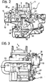
- FIGS 2, 3 show a preferred embodiment of the carburettor 1.
- the elements corresponding to those shown in Figure 1 are indicated by the same reference numerals.
- Reference numeral 25 indicates the shaft of throttle valve 3 to which an actuating lever 26 is connected.
- the lever 26 has one end supporting a spherical element 27 for connection to the usual actuating cable.
- the choke valve actuating mechanism 10 comprises a lever 28 pivoted to the fixed structure of the carburettor around an axis 29 and provided with a belt 30 for connection to the actuating cable 11.
- the actuating mechanism 10 further comprises a lever 31 mounted onto one end of the choke valve shaft 32 and carrying a follower element 33 cooperating with an arm 34 of the lever 28.
- the above-mentioned linkage mechanism connecting the choke valve actuating mechanism 10 to the throttle valve mechanism comprises a lever 35 having its ends cooperating with the lever 28 and the lever 26, respectively.
- levers 28, 26 and 35 are known per se and does not form part of the present invention.
- the actuating rod 24 connected to the diaphragm member 14 has its end opposite to the diaphragm member 14 connected to the lever 28 by means of a spherical joint 36.
- a spring 37 is interposed between the lever 28 and the rod 24 in order to take up any play which may occur between such elements.
- reference numeral 38 indicates a pipe for connection of conduit 18 to the second chamber 17 of the diaphragm device 14.
- the fuel supply system according to the present invention may be of simple and economic construction.
Landscapes
- Engineering & Computer Science (AREA)
- Chemical & Material Sciences (AREA)
- Combustion & Propulsion (AREA)
- Mechanical Engineering (AREA)
- General Engineering & Computer Science (AREA)
- Means For Warming Up And Starting Carburetors (AREA)
Applications Claiming Priority (2)
| Application Number | Priority Date | Filing Date | Title |
|---|---|---|---|
| IT67447/80A IT1128072B (it) | 1980-03-24 | 1980-03-24 | Dispositivo per il controllo del carburante per l avviamento a freddo di un motore a ciclo otto |
| IT6744780 | 1980-03-24 |
Publications (2)
| Publication Number | Publication Date |
|---|---|
| EP0036608A1 EP0036608A1 (en) | 1981-09-30 |
| EP0036608B1 true EP0036608B1 (en) | 1983-11-09 |
Family
ID=11302454
Family Applications (1)
| Application Number | Title | Priority Date | Filing Date |
|---|---|---|---|
| EP81101959A Expired EP0036608B1 (en) | 1980-03-24 | 1981-03-16 | A fuel supply system for an internal combustion engine |
Country Status (8)
| Country | Link |
|---|---|
| US (1) | US4380974A (enExample) |
| EP (1) | EP0036608B1 (enExample) |
| AR (1) | AR224567A1 (enExample) |
| BR (1) | BR8101715A (enExample) |
| DE (1) | DE3161351D1 (enExample) |
| IN (1) | IN153455B (enExample) |
| IT (1) | IT1128072B (enExample) |
| ZA (1) | ZA811681B (enExample) |
Families Citing this family (6)
| Publication number | Priority date | Publication date | Assignee | Title |
|---|---|---|---|---|
| JPS5923050A (ja) * | 1982-07-30 | 1984-02-06 | Sanshin Ind Co Ltd | 内燃機関の始動燃料増量装置 |
| US4553504A (en) * | 1983-12-30 | 1985-11-19 | Cummins Engine Company, Inc. | Means and method for alternate fuel fumigation in internal combustion engines |
| JPS6137451U (ja) * | 1984-08-10 | 1986-03-08 | 三菱自動車工業株式会社 | アルコ−ルエンジンの補助燃料供給装置 |
| BR8801648A (pt) * | 1988-04-07 | 1989-11-07 | Bosch Do Brasil | Sistema de partida a frio para motores de combustao interna a alcool,processo de partida a frio e dispositivo a ser utilizado nos mesmos |
| EP0786591A3 (en) * | 1996-01-29 | 1997-08-13 | WCI OUTDOOR PRODUCTS, Inc. | Fast start fuel system for an internal combustion engine |
| US6135426A (en) * | 1998-01-07 | 2000-10-24 | Briggs And Stratton Corporation | Priming system for internal combustion engines |
Citations (8)
| Publication number | Priority date | Publication date | Assignee | Title |
|---|---|---|---|---|
| US1506229A (en) * | 1916-09-30 | 1924-08-26 | Orville H Ensign | Carburetor |
| FR856966A (fr) * | 1938-06-30 | 1940-08-19 | Carburateur à huile lourde pour moteurs à combustion interne | |
| FR877212A (fr) * | 1940-10-15 | 1942-12-01 | Appareil permettant l'utilisation de carburant à base d'alcool pour les moteurs à explosions | |
| US2597776A (en) * | 1947-09-18 | 1952-05-20 | Milton E Chandler | Auxiliary fuel chamber |
| BE742916A (enExample) * | 1969-03-29 | 1970-05-14 | ||
| US4056087A (en) * | 1976-03-26 | 1977-11-01 | F. Travers Burgess | Two-fuel carburetor |
| FR2361542A1 (fr) * | 1976-08-12 | 1978-03-10 | Fuji Heavy Ind Ltd | Dispositif d'alimentation pour moteur a plusieurs combustibles |
| US4204489A (en) * | 1977-12-21 | 1980-05-27 | Toyota Jidosha Kogyo Kabushiki Kaisha | 2-Cycle engine of an active thermoatmosphere combustion type |
Family Cites Families (7)
| Publication number | Priority date | Publication date | Assignee | Title |
|---|---|---|---|---|
| US1829050A (en) * | 1928-08-18 | 1931-10-27 | Harry W Mcclure | Means for operating internal combustion engines |
| US2821183A (en) * | 1955-12-21 | 1958-01-28 | Vernon D Roosa | Fuel injection means for internal combustion engines |
| US2985159A (en) * | 1957-09-09 | 1961-05-23 | Holley Carburetor Co | Cold starting means for carburetors |
| GB1223925A (en) * | 1968-12-17 | 1971-03-03 | Zenith Carburetter Company Ltd | Improvements in or relating to fuel supply devices for cold starting of internal combustion engines |
| FR2333968A1 (fr) * | 1975-12-02 | 1977-07-01 | Sibe | Perfectionnements aux dispositifs de carburation pour moteurs a combustion interne |
| US4031864A (en) * | 1976-03-09 | 1977-06-28 | The United States Of America As Represented By The United States Energy Research And Development Administration | Multiple fuel supply system for an internal combustion engine |
| US4085720A (en) * | 1976-08-11 | 1978-04-25 | Fuji Jukogyo Kabushiki Kaisha | Fuel supply system for multi-fuel internal combustion engines |
-
1980
- 1980-03-24 IT IT67447/80A patent/IT1128072B/it active
-
1981
- 1981-03-13 ZA ZA00811681A patent/ZA811681B/xx unknown
- 1981-03-16 DE DE8181101959T patent/DE3161351D1/de not_active Expired
- 1981-03-16 EP EP81101959A patent/EP0036608B1/en not_active Expired
- 1981-03-23 BR BR8101715A patent/BR8101715A/pt not_active IP Right Cessation
- 1981-03-23 AR AR284707A patent/AR224567A1/es active
- 1981-03-24 IN IN315/CAL/81A patent/IN153455B/en unknown
- 1981-03-24 US US06/247,031 patent/US4380974A/en not_active Expired - Fee Related
Patent Citations (8)
| Publication number | Priority date | Publication date | Assignee | Title |
|---|---|---|---|---|
| US1506229A (en) * | 1916-09-30 | 1924-08-26 | Orville H Ensign | Carburetor |
| FR856966A (fr) * | 1938-06-30 | 1940-08-19 | Carburateur à huile lourde pour moteurs à combustion interne | |
| FR877212A (fr) * | 1940-10-15 | 1942-12-01 | Appareil permettant l'utilisation de carburant à base d'alcool pour les moteurs à explosions | |
| US2597776A (en) * | 1947-09-18 | 1952-05-20 | Milton E Chandler | Auxiliary fuel chamber |
| BE742916A (enExample) * | 1969-03-29 | 1970-05-14 | ||
| US4056087A (en) * | 1976-03-26 | 1977-11-01 | F. Travers Burgess | Two-fuel carburetor |
| FR2361542A1 (fr) * | 1976-08-12 | 1978-03-10 | Fuji Heavy Ind Ltd | Dispositif d'alimentation pour moteur a plusieurs combustibles |
| US4204489A (en) * | 1977-12-21 | 1980-05-27 | Toyota Jidosha Kogyo Kabushiki Kaisha | 2-Cycle engine of an active thermoatmosphere combustion type |
Also Published As
| Publication number | Publication date |
|---|---|
| AR224567A1 (es) | 1981-12-15 |
| EP0036608A1 (en) | 1981-09-30 |
| ZA811681B (en) | 1982-03-31 |
| BR8101715A (pt) | 1981-10-06 |
| IT8067447A0 (it) | 1980-03-24 |
| IN153455B (enExample) | 1984-07-14 |
| IT1128072B (it) | 1986-05-28 |
| DE3161351D1 (en) | 1983-12-15 |
| US4380974A (en) | 1983-04-26 |
Similar Documents
| Publication | Publication Date | Title |
|---|---|---|
| US3371658A (en) | Priming method and arrangement for fuel feed system | |
| US6213083B1 (en) | Fuel shutoff system | |
| US4056087A (en) | Two-fuel carburetor | |
| US4073278A (en) | Carburator | |
| US3689036A (en) | Air-fuel mixture enriching device for constant vacuum type carburetors | |
| EP0036608B1 (en) | A fuel supply system for an internal combustion engine | |
| US4348338A (en) | Injection-type pressure-freed carburetor | |
| CA1160919A (en) | Dual fuel supply system | |
| US2311828A (en) | Fuel control device | |
| US2985159A (en) | Cold starting means for carburetors | |
| US1932521A (en) | Outboard motor control | |
| US2595721A (en) | Carburetor | |
| US2419956A (en) | Carbureting and fuel supply means for motor-driven vehicles | |
| US4243002A (en) | Fuel injection system for an internal combustion engine | |
| US2653804A (en) | Fuel metering control for injection carburetors | |
| US1978660A (en) | Carburetor | |
| US1958818A (en) | Carburetor | |
| US2847021A (en) | Carburetor float valve stabilizer | |
| US2692766A (en) | Carburetor float valve control | |
| US3495809A (en) | Carburetor fuel bowl inlet arrangement | |
| US3294375A (en) | Carburetor | |
| US3058728A (en) | Throttle-operated inside carburetor vents | |
| US4304200A (en) | Fuel injection systems for mixture compressing spark-ignition internal combustion engine | |
| JPS56121839A (en) | Fuel supply system for start-up of combustion engine | |
| US2362879A (en) | Carburetor |
Legal Events
| Date | Code | Title | Description |
|---|---|---|---|
| PUAI | Public reference made under article 153(3) epc to a published international application that has entered the european phase |
Free format text: ORIGINAL CODE: 0009012 |
|
| AK | Designated contracting states |
Designated state(s): DE FR GB |
|
| 17P | Request for examination filed |
Effective date: 19811026 |
|
| GRAA | (expected) grant |
Free format text: ORIGINAL CODE: 0009210 |
|
| AK | Designated contracting states |
Designated state(s): DE FR GB |
|
| REF | Corresponds to: |
Ref document number: 3161351 Country of ref document: DE Date of ref document: 19831215 |
|
| ET | Fr: translation filed | ||
| PLBE | No opposition filed within time limit |
Free format text: ORIGINAL CODE: 0009261 |
|
| STAA | Information on the status of an ep patent application or granted ep patent |
Free format text: STATUS: NO OPPOSITION FILED WITHIN TIME LIMIT |
|
| 26N | No opposition filed | ||
| PGFP | Annual fee paid to national office [announced via postgrant information from national office to epo] |
Ref country code: GB Payment date: 19930217 Year of fee payment: 13 |
|
| PGFP | Annual fee paid to national office [announced via postgrant information from national office to epo] |
Ref country code: DE Payment date: 19930222 Year of fee payment: 13 |
|
| PGFP | Annual fee paid to national office [announced via postgrant information from national office to epo] |
Ref country code: FR Payment date: 19930330 Year of fee payment: 13 |
|
| PG25 | Lapsed in a contracting state [announced via postgrant information from national office to epo] |
Ref country code: GB Effective date: 19940316 |
|
| GBPC | Gb: european patent ceased through non-payment of renewal fee |
Effective date: 19940316 |
|
| PG25 | Lapsed in a contracting state [announced via postgrant information from national office to epo] |
Ref country code: FR Effective date: 19941130 |
|
| PG25 | Lapsed in a contracting state [announced via postgrant information from national office to epo] |
Ref country code: DE Effective date: 19941201 |
|
| REG | Reference to a national code |
Ref country code: FR Ref legal event code: ST |