EP0035864A2 - Process for upgrading heavy hydrocarbonaceous oils - Google Patents
Process for upgrading heavy hydrocarbonaceous oils Download PDFInfo
- Publication number
- EP0035864A2 EP0035864A2 EP81300887A EP81300887A EP0035864A2 EP 0035864 A2 EP0035864 A2 EP 0035864A2 EP 81300887 A EP81300887 A EP 81300887A EP 81300887 A EP81300887 A EP 81300887A EP 0035864 A2 EP0035864 A2 EP 0035864A2
- Authority
- EP
- European Patent Office
- Prior art keywords
- stream
- hydrogen donor
- residuum
- liquid
- donor material
- Prior art date
- Legal status (The legal status is an assumption and is not a legal conclusion. Google has not performed a legal analysis and makes no representation as to the accuracy of the status listed.)
- Granted
Links
- 238000000034 method Methods 0.000 title claims abstract description 35
- 239000003921 oil Substances 0.000 title claims abstract description 35
- 230000008569 process Effects 0.000 title claims abstract description 34
- 239000000852 hydrogen donor Substances 0.000 claims abstract description 67
- 239000000463 material Substances 0.000 claims abstract description 64
- 238000009835 boiling Methods 0.000 claims abstract description 49
- 239000007788 liquid Substances 0.000 claims abstract description 26
- 238000005336 cracking Methods 0.000 claims abstract description 22
- 150000002431 hydrogen Chemical class 0.000 claims abstract description 13
- 239000002243 precursor Substances 0.000 claims abstract description 9
- 239000001257 hydrogen Substances 0.000 claims description 30
- 229910052739 hydrogen Inorganic materials 0.000 claims description 30
- UFHFLCQGNIYNRP-UHFFFAOYSA-N Hydrogen Chemical compound [H][H] UFHFLCQGNIYNRP-UHFFFAOYSA-N 0.000 claims description 29
- 238000004517 catalytic hydrocracking Methods 0.000 claims description 5
- 230000005484 gravity Effects 0.000 claims description 3
- 239000007789 gas Substances 0.000 description 28
- 238000005984 hydrogenation reaction Methods 0.000 description 14
- IJGRMHOSHXDMSA-UHFFFAOYSA-N Atomic nitrogen Chemical compound N#N IJGRMHOSHXDMSA-UHFFFAOYSA-N 0.000 description 12
- 239000010779 crude oil Substances 0.000 description 12
- 229910052799 carbon Inorganic materials 0.000 description 11
- 239000000047 product Substances 0.000 description 11
- 229930195733 hydrocarbon Natural products 0.000 description 10
- 150000002430 hydrocarbons Chemical class 0.000 description 10
- VNWKTOKETHGBQD-UHFFFAOYSA-N methane Chemical compound C VNWKTOKETHGBQD-UHFFFAOYSA-N 0.000 description 10
- 239000010426 asphalt Substances 0.000 description 9
- 239000003054 catalyst Substances 0.000 description 7
- 238000004508 fractional distillation Methods 0.000 description 7
- 238000000629 steam reforming Methods 0.000 description 7
- OKTJSMMVPCPJKN-UHFFFAOYSA-N Carbon Chemical compound [C] OKTJSMMVPCPJKN-UHFFFAOYSA-N 0.000 description 6
- 239000004215 Carbon black (E152) Substances 0.000 description 6
- 238000009903 catalytic hydrogenation reaction Methods 0.000 description 6
- 238000006243 chemical reaction Methods 0.000 description 6
- 239000000571 coke Substances 0.000 description 6
- 238000004821 distillation Methods 0.000 description 6
- 229910052757 nitrogen Inorganic materials 0.000 description 6
- 238000004227 thermal cracking Methods 0.000 description 6
- 239000000295 fuel oil Substances 0.000 description 5
- 239000000203 mixture Substances 0.000 description 5
- CURLTUGMZLYLDI-UHFFFAOYSA-N Carbon dioxide Chemical compound O=C=O CURLTUGMZLYLDI-UHFFFAOYSA-N 0.000 description 4
- RWSOTUBLDIXVET-UHFFFAOYSA-N Dihydrogen sulfide Chemical compound S RWSOTUBLDIXVET-UHFFFAOYSA-N 0.000 description 4
- 230000008901 benefit Effects 0.000 description 4
- 238000010438 heat treatment Methods 0.000 description 4
- 239000012263 liquid product Substances 0.000 description 4
- 238000004939 coking Methods 0.000 description 3
- 230000000694 effects Effects 0.000 description 3
- 238000005194 fractionation Methods 0.000 description 3
- 238000004949 mass spectrometry Methods 0.000 description 3
- 150000002790 naphthalenes Chemical class 0.000 description 3
- 238000004064 recycling Methods 0.000 description 3
- 238000005292 vacuum distillation Methods 0.000 description 3
- NINIDFKCEFEMDL-UHFFFAOYSA-N Sulfur Chemical compound [S] NINIDFKCEFEMDL-UHFFFAOYSA-N 0.000 description 2
- 239000005864 Sulphur Substances 0.000 description 2
- 238000004458 analytical method Methods 0.000 description 2
- 230000015572 biosynthetic process Effects 0.000 description 2
- 239000001569 carbon dioxide Substances 0.000 description 2
- 229910002092 carbon dioxide Inorganic materials 0.000 description 2
- 238000001816 cooling Methods 0.000 description 2
- 230000003247 decreasing effect Effects 0.000 description 2
- 239000000386 donor Substances 0.000 description 2
- 239000002737 fuel gas Substances 0.000 description 2
- 238000011065 in-situ storage Methods 0.000 description 2
- 238000004519 manufacturing process Methods 0.000 description 2
- 230000004048 modification Effects 0.000 description 2
- 238000012986 modification Methods 0.000 description 2
- 239000003345 natural gas Substances 0.000 description 2
- 230000003647 oxidation Effects 0.000 description 2
- 238000007254 oxidation reaction Methods 0.000 description 2
- 239000003208 petroleum Substances 0.000 description 2
- 238000012545 processing Methods 0.000 description 2
- 239000011541 reaction mixture Substances 0.000 description 2
- 238000002407 reforming Methods 0.000 description 2
- 238000012546 transfer Methods 0.000 description 2
- 241000272194 Ciconiiformes Species 0.000 description 1
- -1 Lloydminster) Substances 0.000 description 1
- 238000013459 approach Methods 0.000 description 1
- 239000006227 byproduct Substances 0.000 description 1
- 125000004432 carbon atom Chemical group C* 0.000 description 1
- 230000003197 catalytic effect Effects 0.000 description 1
- 239000003795 chemical substances by application Substances 0.000 description 1
- 230000002950 deficient Effects 0.000 description 1
- 239000003085 diluting agent Substances 0.000 description 1
- 238000010790 dilution Methods 0.000 description 1
- 239000012895 dilution Substances 0.000 description 1
- 238000006073 displacement reaction Methods 0.000 description 1
- 239000012530 fluid Substances 0.000 description 1
- 238000004231 fluid catalytic cracking Methods 0.000 description 1
- 230000007246 mechanism Effects 0.000 description 1
- 229910052751 metal Inorganic materials 0.000 description 1
- 239000002184 metal Substances 0.000 description 1
- 150000002739 metals Chemical class 0.000 description 1
- 238000002156 mixing Methods 0.000 description 1
- 238000005504 petroleum refining Methods 0.000 description 1
- 239000002574 poison Substances 0.000 description 1
- 231100000614 poison Toxicity 0.000 description 1
- 238000005086 pumping Methods 0.000 description 1
- 239000011819 refractory material Substances 0.000 description 1
- 230000008929 regeneration Effects 0.000 description 1
- 238000011069 regeneration method Methods 0.000 description 1
- 239000004576 sand Substances 0.000 description 1
- 229930195734 saturated hydrocarbon Natural products 0.000 description 1
- 238000007789 sealing Methods 0.000 description 1
- 238000000926 separation method Methods 0.000 description 1
- 239000003079 shale oil Substances 0.000 description 1
- 239000002904 solvent Substances 0.000 description 1
- 230000000638 stimulation Effects 0.000 description 1
- 239000000126 substance Substances 0.000 description 1
- 239000011269 tar Substances 0.000 description 1
- 239000011275 tar sand Substances 0.000 description 1
- CXWXQJXEFPUFDZ-UHFFFAOYSA-N tetralin Chemical class C1=CC=C2CCCCC2=C1 CXWXQJXEFPUFDZ-UHFFFAOYSA-N 0.000 description 1
- 239000002699 waste material Substances 0.000 description 1
Images

Classifications
-
- C—CHEMISTRY; METALLURGY
- C10—PETROLEUM, GAS OR COKE INDUSTRIES; TECHNICAL GASES CONTAINING CARBON MONOXIDE; FUELS; LUBRICANTS; PEAT
- C10G—CRACKING HYDROCARBON OILS; PRODUCTION OF LIQUID HYDROCARBON MIXTURES, e.g. BY DESTRUCTIVE HYDROGENATION, OLIGOMERISATION, POLYMERISATION; RECOVERY OF HYDROCARBON OILS FROM OIL-SHALE, OIL-SAND, OR GASES; REFINING MIXTURES MAINLY CONSISTING OF HYDROCARBONS; REFORMING OF NAPHTHA; MINERAL WAXES
- C10G47/00—Cracking of hydrocarbon oils, in the presence of hydrogen or hydrogen- generating compounds, to obtain lower boiling fractions
- C10G47/32—Cracking of hydrocarbon oils, in the presence of hydrogen or hydrogen- generating compounds, to obtain lower boiling fractions in the presence of hydrogen-generating compounds
- C10G47/34—Organic compounds, e.g. hydrogenated hydrocarbons
-
- C—CHEMISTRY; METALLURGY
- C10—PETROLEUM, GAS OR COKE INDUSTRIES; TECHNICAL GASES CONTAINING CARBON MONOXIDE; FUELS; LUBRICANTS; PEAT
- C10G—CRACKING HYDROCARBON OILS; PRODUCTION OF LIQUID HYDROCARBON MIXTURES, e.g. BY DESTRUCTIVE HYDROGENATION, OLIGOMERISATION, POLYMERISATION; RECOVERY OF HYDROCARBON OILS FROM OIL-SHALE, OIL-SAND, OR GASES; REFINING MIXTURES MAINLY CONSISTING OF HYDROCARBONS; REFORMING OF NAPHTHA; MINERAL WAXES
- C10G2400/00—Products obtained by processes covered by groups C10G9/00 - C10G69/14
- C10G2400/06—Gasoil
Definitions
- This invention relates to a process for improving the quality of heavy, viscous crude oils. More specifically, it relates to a process comprising separating the viscous crude into fractions by fractional distillation, and cracking and hydrogenating. the highest boiling fraction so obtained in the presence of a recycled hydrogen donor material obtained by separating particular portions of the resulting cracked material and catalytically rehydrogenating a specific portion so produced to prepare said hydrogen donor material for recycling.
- the fractionated streams produced in separating said viscous crude and in separating said hydrogenated cracked material are suitable for further hydrogenation and/or recombining into a reconstituted crude oil, or for use in normal refinery processes without being'recombined.
- Hydrogen donor materials are well known for their ability to release hydrogen to a hydrogen-deficient oil in a thermal cracking zone, and thereby to convert heavy hydrocarbon oils to more valuable.lower-boiling products.
- the hydrogen donor is aromatic-naphthenic in nature and, having. released hydrogen in the thermal cracking zone, can be catalytically rehydrogenated in a separate hydrogenation zone and recycled as a hydrogen donor.
- Hydrogen donor cracking processes make possible the conversion of heavy oils in the absence of a catalyst and with the formation of little, if any, coke, and at substantially lower pressures than are necessary with the use of molecular hydrogen in hydrocracking.
- the present invention is a process for the upgrading of heavy, viscous hydrocarbonaceous oils comprising:
- the invention comprises steps (a) to (f) noted above, wherein fractional distillation step (a) is carried out to produce a naphtha stream, a distillate stream and a gas oil stream as well as the aforementioned residuum, and the lower and higher boiling fractions from fractional distillation step (d) are utilized as follows: the overhead stream is combined with said naphtha stream from step (a), a heavy gas oil stream is combined with said gas oil stream from step (a) and these streams as well as a bottoms stream from step (d) are withdrawn as product'streams.
- the gaseous stream obtained at step (c) can be desulphurized to produce a desulphurized gaseous stream, and said desulphurized gaseous stream can be reformed with steam to form a hydrogen-rich gaseous stream for use in step (e) and by-product carbon dioxide.
- the gaseous stream from step (c) can be used as fuel gas and the external supply of methane-rich gas can be utilized as the source of hydrogen for the reforming step.
- the aforementioned hydrogenated hydrogen donor material stream is fractionally distilled to separate, from lower and higher boiling materials, an optimized hydrogenated hydrogen donor material, which lower and higher boiling materials are combined with the appropriate product stream or streams.
- said product streams can individually be catalytically reacted with a hydrogen-rich gas, to produce more fully upgraded streams which can be used in a conventional oil refinery, or alternatively they canbe combined with the bottoms stream from step (d) to produce a fully upgraded, lower viscosity synthetic crude.
- the process of the invention is applicable to upgrading various types of heavy crudes, including in-situ heavy oils (e.g. Lloydminster), oil sands bitumen (e.g. Athabasca), and generally any type of crude oil whose composition and viscosity in the raw form are such that they render it difficult or impossible to process the oil in a conventional oil refinery or to transport in a pipeline without dilution or external heating or tracing of the pipeline and consequent large-scale waste of energy.
- in-situ heavy oils e.g. Lloydminster
- oil sands bitumen e.g. Athabasca
- raw crude oil in stream 21 is distilled to remove material distillable without thermal cracking.
- the distillation is preferably carried out in two stages, the first at atmospheric pressure in fractionating column 1 with overheads going via line 22 and residue via line 25, and the second under vacuum in fractionating column 2, from which overheads go via line 26 and residue or bottoms via 27.
- the amount of absolute pressure in column 2 can be varied to as low as 2 kPa but is normally selected for minimum steam usage, and commercial operations are commonly conducted at 2.5 - 4 kPa.
- the bottoms stream from vacuum distillation step 2 can have an initial boiling point varying over a.wide range, depending upon the type of crude and process conditions.
- a small upgrading plant (1500 - 3000 m 3 /day)
- the bottoms stream 27 is contacted in reactor 3 with a hydrogenated recycled stream 30.
- An initial supply of hydrogen donor material for start-up is fed through line 29 until adequate flow in stream 30 is established.
- the recycled stream has the ability to donate hydrogen and is used in a weight ratio of substantially 1:0.5 to 1:4 and a temperature of substantially . 350°C to 500°C, preferably 400°C to 460°C and at an absolute pressure of substantially 2 to 15 MPa, preferably 2.5 to 6 MPa, and a reaction mass liquid space velocity of substantially 0.5 to 10.0 h -1 , preferably 0.8 to 7.0 h -1 .
- No catalyst is necessary in the hydrogen donor cracking reaction. Under the preferred conditions no coke is produced in the reaction.
- Effluent from reactor 3 passes via line 31 to gas separator 4, which separates gases including hydrocarbons boiling at ambient room temperature or lower.
- gaseous material in stream 32 is treated to remove hydrogen sulphide in desulphurization zone 6 and is passed via line 39 into a steam reforming zone 7 along with external steam in stream 41, forming a hydrogen-rich gas passing via line 42 to be used in catalytic hydrogenation zone 8.
- Sulphur is removed from zone 6 via line 40 and carbon dioxide-rich gas from zone 7 is discharged via line 43.
- the liquid reactor effluent 33 from separator 4 is fractionated in fractionating still 5, and the distilled portion boiling for example from substantially 180°C to substantially 350°C, preferably from 200°C to 330°C, in stream 35, is rehydrogenated in catalytic hydrogenation zone 8.
- the upper and lower limits of the boiling range of stream 35 may be adjusted as necessary to obtain an appropriate volume of hydrogen donor material for stream - 30..
- Overhead fractions 22, 26 and 34, gas oil fraction 36 and residuum fraction 37 can be combined into a reconstituted "crude" in stream 53 which has sufficiently low viscosity that it is suitable for pumping.
- a portion of residuum fraction 37 can optionally be recycled through line 38 to be combined with bottoms stream 27 and reprocessed through the hydrogen donor cracking zone.
- the reaction in hydrogenation zone 8 normally does not consume all the hydrogen from stream 42 and the unused gases which are contaminated with hydrogen sulphide can be recycled to the inlet of desulphurization zone 6, via line 45.
- the hydrogen donor capability of the fraction in stream 35 is sufficient, when the latter has undergone catalytic hydrogenation in zone 8, to continue the hydrogen donor cracking without adding make-up hydrogen donor material via line 29.
- the hydrogen-rich gas in stream 42 is used to hydrogenate the fraction in stream 35 under usual catalytic hydrogenation conditions in zone 8 and the effluent stream of liquid hydrogenated material 44 is passed either directly to line 47 thence to line 30 where it is recycled into hydrogen donor cracking zone 3, or via line 54 to a fractionation, hereafter described with reference to Figure 3, and return of a fraction thereof via line 55 to line 47.
- the gaseous materials formed in the hydrocracking step and separated at step 4 include methane and other hydrocarbons having up to substantially five carbon atoms in their molecules. These latter materials have lower hydrogen-to- carbon ratios, hence may be more useful for their heating - value than for their hydrogen content.
- the imported gas stream can be for example natural gas and can contain hydrogen; it is desulphurized if it is sour, in the desulphurization zone 6 as shown in Fingure 1, or taken directly to steam reforming zone 7, as appropriate.
- the gaseous stream 32 may be desulphurized if necessary in a desulphurization zone, or taken directly to product via line 57, as shown in Figure 1.
- An optional source of hydrogen for use in hydrogenating zone 8 is the steam reforming of a residuum in steam reforming zone 7, instead of reforming the gaseous material separated at step 4.
- An advantageous source of residuum for this purpose is stream 37, the bottoms from fractionation step S.
- Suitable hydrogen donor or hydrogen donor precursor material for starting up the process can be obtained for example, in certain refinery streams known in the art. If necessary or desirable, it can be hydrogenated in the described hydrogenation zone 8 prior to contacting with fractionating tower bottoms stream 27 in hydrogen donor cracking zone 3. .
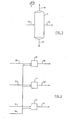
- Figure 2 employing identical numbers for parts identical to those shown in Figure 1, illustrates an optional processing scheme wherein the initial crude 21 is fractionally distilled into a plurality of cuts 22, 23 and 24 each of whose initial and final boiling points can be selected as is customary in petroleum refining to produce- appropriate streams.
- Commonly used fractions are naphtha, distillate and gas oil, although fewer or more than three fractions can be taken without departing from the scope of the invention.
- the fractions resulting from the distillation step 5 in streams 34 and 36 can be combined with the appropriate fractions from the crude distillation, i.e. fractions of similar boiling ranges, to obtain a plurality of product streams 49, 51 and 50.
- the bottoms stream 37 from fractional distillation step 5 can be kept as a separate product stream.
- the hydrogenated hydrogen donor material in stream 44 from zone 8 optionally can be passed via line 54 and fractionally distilled in distillation column 9 to separate, from lower and higher boiling materials 46 and 48, a hydrogen donor heart cut 55, boiling for example in the range from substantially 220°C to substantially 295°C, which can be fed through line 47 to hydrogen donor cracking zone 3.
- the lower boiling material 46 can be combined for example with naphtha stream 49 and the higher boiling material 48 combined for example with gas oil stream 50 ( Figure 2), or if desired, both can be combined with the product stream 53 ( Figure -1).
- the hydrogen donor activity of the lower boiling and higher boiling streams 46 and 48 is lower than that of the heart cut 55 and their removal has the effect of raising the concentration of active hydrogen donor material recycled to the hydrogen-donor cracking zone 3.
- FIG. 4 A modification of the embodiments of the invention outlined in Figures 1 and 2 is shown in Figure 4.
- the reconstituted naphtha, distillate and gas oil streams 49, 50 and 51, obtained as shown in Figure 2, can optionally be further hydrogenated individually.at catalytic hydrogenation steps 10, 11 and 12 by known methods.
- a hydrogen-rich gas can be introduced from an external-source via line 58 and the resulting hydrogenated naphtha stream 59, hydrogenated distillate stream 60 and hydrogenated gas oil stream 61 are therefore suitable for direct use in a conventional oil refinery.
- these hydrogenated streams can be combined with the residuum stream 37 ( Figure 1) to obtain in stream 53 an upgraded, lower viscosity pipelineable synthetic crude oil suitable for use in conventional oil refineries remote from the upgrading plant. Because of its higher hydrogen:carbon ratio, the synthetic crude oil can give higher quality products with less processing than less ' highly hydrogenated synthetic crude oils.
- An advantage of the present process is that it can be used in a small production area to provide crude capable of being transported by pipeline to an appropriate refinery.
- a further advantage is that the process at proper operating conditions produces no coke.
- a still further advantage is that it uses as the hydrogen transfer material a fraction of the heavy crude that is generated in the process itself, and therefore no additional hydrogen transfer agent is needed . after the initial start-up.
- Another advantage of this process is that it can convert as much as 90 per cent of the high boiling components in the crude, i.e. components boiling at greater than about 504°C, to components boiling at less than about 504°C.
- the products streams can be used in any of several optional ways, enabling the process to be tailored to actual field conditions.
- 497 parts of the vacuum residuum was thoroughly blended with 497 parts of a hydrocarbon stream serving as an initial hydrogen donor stream.
- This donor stream was the heart cut obtained by hydrotreating a fluid catalytically cracked fraction that boiled in the range 193°C to 343°C and fractionally distilling the hydrotreated material to obtain a heart cut boiling in the range 221°C to 293°C; the donor stream had a content of 48.7 per cent by weight of benzocycloparaffins (predominantly substituted tetrahydronaphthalenes) and 19.4 per cent naphthalenes, as determined by low resolution mass spectrometry. After sealing the autoclave, the air was displaced therefrom by nitrogen and a residual pressure of 0.65 MPa absolute left in the vessel.
- the vessel was then stirred and heated to an internal temperature of 415°C at-a rate of substantially 5.3°C per minute and maintained at this temperature for a hydrogen donor cracking period of 81 minutes before cooling was begun. During this constant temperature period the pressure in the vessel increased from 3.0 MPa to 8.3 MPa. After cooling to ambient temperature (22°C, at which the pressure was 2.34-MPa) the gas was discharged from the autoclave and its volume measured (36.6 litres at NTP, including the nitrogen of the residual nitrogen pressure). The total evolved gas.(nitrogen free basis) amounted to 4.6 per cent by weight of the material charged to the autoclave; on analysis the gas was found to have a composition, on a nitrogen free basis, approximately as shown in Table -1.
- 803 parts was fractionally distilled to yield three fractions, viz: (a) an initial fraction, having a boiling range up to 204°C and amounting to 102 parts, (b) a mid-fraction having a boiling range from 204°C to 316°C and amounting to 421 parts, and (c) a residue boiling above 316"C and amounting to 280 parts.
- a sample of this residue was further fractionated to separate material boiling above 491°C and amounting to 54.5 per cent by weight of the residue sample. It was thus calculated that 63.6 per cent of the original vacuum residuum (all of which boiled above 491°C) was converted to material with a boiling point below 491°C.
- the (b) fraction with a boiling range 204°C to 316°C from a duplicate operation as described above was rehydrogenated under catalytic hydrogenation conditions as follows. 459 parts of the fraction, and 50 parts of commercial hydrogenation catalyst designated as NT550 (supplied by Nalco Chemical Company) were sealed in a two litre autoclave, purged with nitrogen to remove air, then pressured with hydrogen to 5.62 MPa at 23°C. The stirred autoclave then was heated at a rate of 4.5°C per minute until a temperature of 305°C was reached. Pressure in the vessel rose to 9.33 MPa during heating.
- the temperature was maintained at 305°C for the next 4.7 hours during which the autoclave was further repressured with hydrogen as recorded pressure readings indicated hydrogen was consumed by reaction with the fraction, to maintain a minimum pressure of 10.5 MPa, final hydrogenation pressure being 11.47 MPa. Heating was then stopped and the vessel allowed to cool to room temperature (23°C). Pressure at this time was 4.42 MPa. The gas was discharged and on analysis was found to be predominantly hydrogen with some hydrogen sulphide and gaseous hydrocarbon. The hydrogenated liquid was recovered and found to amount to 452 parts by weight.
- the rehydrogenated material, prepared as described above, was used as the hydrogen donor stream for blending with another sample of vacuum residuum of bitumen in the autoclave, as described at the beginning of this example, and was found effective, after a hydrogen donor cracking period as described above, to convert the residuum and form additional reconstituted crude of improved properties as described above.
- a sample of hydrogen donor material as was used in Example 1 and prepared by hydrogenating a light cycle oil obtained from a fluid catalytic cracking unit, was mixed in .a 1:1 ratio with the residuum from a vacuum distillation of Athabasca oil sands bitumen.
- the residuum constituted 54.5 per cent of the bitumen and had an initial boiling point of 505°C.
- the mixture was fed by a positive displacement pump at a rate of 598.8 g/hour into a tubular hydrogen donor cracking reactor of 989 ml volume and 22.9 m length, coiled into a helical shape and immersed in a fluidized sand bed maintained at constant temperature of 432°C.
- the reactor was equipped with a reciprocating mechanism to maintain turbulent flow conditions in the reactor, as disclosed in co-pending patent application &.N..
- the reaction mixture at 5.7 MPa, flowed through a'pressure control valve downstream from the reactor tube and thence into a series of flash separation zones which separated the gaseous portion from the liquids portion of the reactor effluent.
- the flow rate of the gaseous stream was measured and the composition determined using an on-line gas chromatograph.
- the hydrocarbon content of the evolved gas was found to be sufficient to provide (by steam reforming) the hydrogen requirements for hydrogenation of the hydrogen donor precursor material separated from the liquids portion of the reactor effluent.
- the liquid portion of the reactor effluent was fractionally distilled to separate a fraction boiling in the range 193° C to 332°C and amounting to 56.3% of the liquid products. This fraction was hydrogenated catalytically, over the same hydrogenation catalyst used in Example 1, at around 320°C for 5.6 hours.
Landscapes
- Chemical & Material Sciences (AREA)
- Oil, Petroleum & Natural Gas (AREA)
- Engineering & Computer Science (AREA)
- Chemical Kinetics & Catalysis (AREA)
- General Chemical & Material Sciences (AREA)
- Organic Chemistry (AREA)
- Production Of Liquid Hydrocarbon Mixture For Refining Petroleum (AREA)
Abstract
- (a) said liquid hydrocracked stream is fractionally distilled to separate from higher and lower boiling fractions a hydrogen donor precursor stream boiling above a temperature from substantially 180°C to substantially 200°C and below a temperature from substantially 330°C to substantially 350°C,
- (b) at least part of said hydrogenated hydrogen donor material is recycled as the material which constitutes the entire liquid hydrogen donor material stream to contact said residuum.
Description
- This invention relates to a process for improving the quality of heavy, viscous crude oils. More specifically, it relates to a process comprising separating the viscous crude into fractions by fractional distillation, and cracking and hydrogenating. the highest boiling fraction so obtained in the presence of a recycled hydrogen donor material obtained by separating particular portions of the resulting cracked material and catalytically rehydrogenating a specific portion so produced to prepare said hydrogen donor material for recycling. The fractionated streams produced in separating said viscous crude and in separating said hydrogenated cracked material are suitable for further hydrogenation and/or recombining into a reconstituted crude oil, or for use in normal refinery processes without being'recombined.
- The properties of heavy crudes, i.e. in-situ heavy oils and oil sands bitumen, have long been known. These materials are abundant in Canada and several other countries and are of increasing importance as conventional, i.e. lighter, crude oils are depleted. Among the properties of these materials are a low hydrogen:carbon ratio, high viscosity, and a high proportion of components which cannot be vacuum distilled without undergoing thermal cracking. As a result, these heavy oils are impossible to transport through normal crude pipelines or to process in existing refineries. The prior art has shown that (1) carbon rejection, i.e. coking, and (2) hydrogen addition are the two basic approaches to be used in upgrading such crude oils. The term "upgrading" can take various meanings in various contexts. For clarity and consistency, it is here defined as raising the hydrogen:carbon ratio, and lowering the viscosity, specific gravity and average molecular weight of a heavy, viscous hydrocarbonaceous oil. Carbon rejection has the disadvantage of producing a large quantity of refractory materials such as coke which then must be disposed of and which detract from the total amount of liquid product available. Hydrogenation on the other hand produces a larger quantity of valuable liquid products and is more desirable than carbon rejection if the hydrogenation can be carried out at reasonable cost.
- Hydrogen donor materials are well known for their ability to release hydrogen to a hydrogen-deficient oil in a thermal cracking zone, and thereby to convert heavy hydrocarbon oils to more valuable.lower-boiling products. The hydrogen donor is aromatic-naphthenic in nature and, having. released hydrogen in the thermal cracking zone, can be catalytically rehydrogenated in a separate hydrogenation zone and recycled as a hydrogen donor. Hydrogen donor cracking processes make possible the conversion of heavy oils in the absence of a catalyst and with the formation of little, if any, coke, and at substantially lower pressures than are necessary with the use of molecular hydrogen in hydrocracking.
- . In USP 2,953,513 it was disclosed that certain distillate thermal tars, boiling above 371°C, will, upon partial hydrogenation, produce a hydrogen donor material which can be used to hydrocrack heavy feedstocks at temperatures above 427°C. The hydrogen donor material can be rehydrogenatcd using external hydrogen and recycled to the thermal cracking stage(s).
- In US? 4,115,246 a process was disclosed in which the pitch fraction resulting from fractional distillation of the products- of a hydrogen donor diluent cracking step is subjected to a partial oxidation process, and the resulting hydrogen-containing gas produced by the partial oxidation step is utilized to hydrogenate the recycled hydrogen donor solvent. The pitch fraction was defined as the product of the fractional distillation boiling above 500°C. It was disclosed that the fresh feedstock to the cracking furnace could include shale oil, tar sand bitumen, or residual oil from a petroleum refinery.
- Many of the processes known in the art are designed for application in a conventional petroleum refinery; these processes do not address the problem of transporting the crude oil from the well site to the refinery. The coking processes in general form excessive amounts of coke, which must be discarded or desulphurized and burned, and which lower the yield of useful hydrocarbons. In those processes in which catalysts are used, metals present in the crude have a tendency to poison the catalyst and create the necessity for frequent regeneration or replacement of the catalyst.
- In the ensuing description and claims, all references to proportions, percentages, and parts are on a weight basis and all references to boiling points of materials are to atmospheric pressure boiling points, unless otherwise specifically indicated.
- The present invention is a process for the upgrading of heavy, viscous hydrocarbonaceous oils comprising:
- (a) fractionally distilling said hydrocarbonaceous oil to produce at least one fraction boiling below a temperature from substantially 300°C to substantially 570°C and a residuum boiling above said temperature, without significantly cracking said hydrocarbonaceous oil,
- (b) contacting said residuum with a liquid hydrogen donor material stream at hydrocracking conditions to produce a hydrocracked stream,
- (c) separating said hydrocracked stream into a gaseous stream and a liquid hydrocracked stream,
- (d) fractionally distilling said liquid hydrocracked stream to separate, from lower and higher boiling fractions, a hydrogen donor precursor stream boiling above a temperature from substantially 180°C to substantially 200°C and below a temperature from substantially 330°C to substantially 350°C,
- (e) catalytically reacting said hydrogen donor precursor stream with a hydrogen-rich gaseous stream to produce a hydrogenated hydrogen donor material, and
- (f) recycling at least part of said hydrogenated hydrogen donor material as the material which constitutes the entire liquid hydrogen donor material stream to contact said residuum in step (b) noted above.
- In a specific embodiment, the invention comprises steps (a) to (f) noted above, wherein fractional distillation step (a) is carried out to produce a naphtha stream, a distillate stream and a gas oil stream as well as the aforementioned residuum, and the lower and higher boiling fractions from fractional distillation step (d) are utilized as follows: the overhead stream is combined with said naphtha stream from step (a), a heavy gas oil stream is combined with said gas oil stream from step (a) and these streams as well as a bottoms stream from step (d) are withdrawn as product'streams.
- Optionally, the gaseous stream obtained at step (c) can be desulphurized to produce a desulphurized gaseous stream, and said desulphurized gaseous stream can be reformed with steam to form a hydrogen-rich gaseous stream for use in step (e) and by-product carbon dioxide. Alternatively, where an external supply of methane-rich gas (e.g. natural gas) is advantageously available, the gaseous stream from step (c) can be used as fuel gas and the external supply of methane-rich gas can be utilized as the source of hydrogen for the reforming step.
- Preferably, the aforementioned hydrogenated hydrogen donor material stream is fractionally distilled to separate, from lower and higher boiling materials, an optimized hydrogenated hydrogen donor material, which lower and higher boiling materials are combined with the appropriate product stream or streams.
- . Optionally, where it is desirable, said product streams can individually be catalytically reacted with a hydrogen-rich gas, to produce more fully upgraded streams which can be used in a conventional oil refinery, or alternatively they canbe combined with the bottoms stream from step (d) to produce a fully upgraded, lower viscosity synthetic crude.
- The process of the invention is applicable to upgrading various types of heavy crudes, including in-situ heavy oils (e.g. Lloydminster), oil sands bitumen (e.g. Athabasca), and generally any type of crude oil whose composition and viscosity in the raw form are such that they render it difficult or impossible to process the oil in a conventional oil refinery or to transport in a pipeline without dilution or external heating or tracing of the pipeline and consequent large-scale waste of energy.
- In drawings which illustrate an embodiment of the invention and variations,
- Figure 1 is a schematic flow sheet illustrating the basic process of the invention,
- Figure 2 is a schematic flow sheet showing a specific group of fractionated streams,
- Figure 3 is a schematic flow sheet showing a more complex process of obtaining an optimum recycled hydrogen donor material, and
- Figure 4 is a schematic flow sheet showing a further treatment of the streams shown in Figure 2.
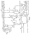
- Referring to Figure 1, raw crude oil in
stream 21 is distilled to remove material distillable without thermal cracking. In order to avoid unwanted cracking and coking in distilling the more refractory components of the mixture, the distillation is preferably carried out in two stages, the first at atmospheric pressure in fractionating column 1 with overheads going vialine 22 and residue vialine 25, and the second under vacuum in fractionating column 2, from which overheads go vialine 26 and residue or bottoms via 27. The amount of absolute pressure in column 2 can be varied to as low as 2 kPa but is normally selected for minimum steam usage, and commercial operations are commonly conducted at 2.5 - 4 kPa. The bottoms stream from vacuum distillation step 2 can have an initial boiling point varying over a.wide range, depending upon the type of crude and process conditions. Bottoms with an initial boiling point as low as 300°C or as high as 570°C, preferrably in the range from 450°C to 570°C, can be used in the process, although for reasons of economics it may be advantageous to remove as much distillate material as possible to reduce the volume of reaction mixture and consequently the size and cost of a hydrogen donor cracking zone 3. Under some circumstances, for example in the use of a small upgrading plant (1500 - 3000 m3/day), it may be desirable to omit a vacuum tower foe crude fractionation and thus to feed to hydrogen donor cracking zone 3 a bottoms stream having an initial boiling point in the range associated with atmospheric tower bottoms, 300°C to 330°C. Thebottoms stream 27 is contacted in reactor 3 with a hydrogenated recycledstream 30. An initial supply of hydrogen donor material for start-up is fed throughline 29 until adequate flow instream 30 is established. The recycled stream has the ability to donate hydrogen and is used in a weight ratio of substantially 1:0.5 to 1:4 and a temperature of substantially . 350°C to 500°C, preferably 400°C to 460°C and at an absolute pressure of substantially 2 to 15 MPa, preferably 2.5 to 6 MPa, and a reaction mass liquid space velocity of substantially 0.5 to 10.0 h-1, preferably 0.8 to 7.0 h-1. No catalyst is necessary in the hydrogen donor cracking reaction. Under the preferred conditions no coke is produced in the reaction. Effluent from reactor 3 passes vialine 31 to gas separator 4, which separates gases including hydrocarbons boiling at ambient room temperature or lower. Alternatively and particularly advantageously,, gaseous material instream 32 is treated to remove hydrogen sulphide indesulphurization zone 6 and is passed vialine 39 into a steam reforming zone 7 along with external steam instream 41, forming a hydrogen-rich gas passing vialine 42 to be used in catalytic hydrogenation zone 8. Sulphur is removed fromzone 6 vialine 40 and carbon dioxide-rich gas from zone 7 is discharged vialine 43. Theliquid reactor effluent 33 from separator 4 is fractionated in fractionating still 5, and the distilled portion boiling for example from substantially 180°C to substantially 350°C, preferably from 200°C to 330°C, instream 35, is rehydrogenated in catalytic hydrogenation zone 8. The upper and lower limits of the boiling range ofstream 35 may be adjusted as necessary to obtain an appropriate volume of hydrogen donor material for stream - 30..Overhead fractions gas oil fraction 36 andresiduum fraction 37 can be combined into a reconstituted "crude" instream 53 which has sufficiently low viscosity that it is suitable for pumping. A portion ofresiduum fraction 37 can optionally be recycled throughline 38 to be combined withbottoms stream 27 and reprocessed through the hydrogen donor cracking zone. The reaction in hydrogenation zone 8 normally does not consume all the hydrogen fromstream 42 and the unused gases which are contaminated with hydrogen sulphide can be recycled to the inlet ofdesulphurization zone 6, vialine 45. During operation, the hydrogen donor capability of the fraction instream 35 is sufficient, when the latter has undergone catalytic hydrogenation in zone 8, to continue the hydrogen donor cracking without adding make-up hydrogen donor material vialine 29. The hydrogen-rich gas instream 42 is used to hydrogenate the fraction instream 35 under usual catalytic hydrogenation conditions in zone 8 and the effluent stream of liquidhydrogenated material 44 is passed either directly toline 47 thence to line 30 where it is recycled into hydrogen donor cracking zone 3, or vialine 54 to a fractionation, hereafter described with reference to Figure 3, and return of a fraction thereof vialine 55 toline 47. The gaseous materials formed in the hydrocracking step and separated at step 4 include methane and other hydrocarbons having up to substantially five carbon atoms in their molecules. These latter materials have lower hydrogen-to- carbon ratios, hence may be more useful for their heating - value than for their hydrogen content. It may, therefore, be advantageous to take these materials to fuel-gas vialine 57, and at the same time to utilize an external gas stream in the steam reforming step by importing it throughline 56. r The imported gas stream can be for example natural gas and can contain hydrogen; it is desulphurized if it is sour, in thedesulphurization zone 6 as shown in Fingure 1, or taken directly to steam reforming zone 7, as appropriate. Similarly thegaseous stream 32 may be desulphurized if necessary in a desulphurization zone, or taken directly to product vialine 57, as shown in Figure 1. - An optional source of hydrogen for use in hydrogenating zone 8 is the steam reforming of a residuum in steam reforming zone 7, instead of reforming the gaseous material separated at step 4. An advantageous source of residuum for this purpose is
stream 37, the bottoms from fractionation step S. - Suitable hydrogen donor or hydrogen donor precursor material for starting up the process can be obtained for example, in certain refinery streams known in the art. If necessary or desirable, it can be hydrogenated in the described hydrogenation zone 8 prior to contacting with fractionating tower bottoms stream 27 in hydrogen donor cracking zone 3. .
- Figure 2, employing identical numbers for parts identical to those shown in Figure 1, illustrates an optional processing scheme wherein the
initial crude 21 is fractionally distilled into a plurality ofcuts distillation step 5 instreams product streams fractional distillation step 5 can be kept as a separate product stream. - Referring to Figure 3, which is to be considered in conjunction with the embodiments of either Figure 1 or Figure . 2, the hydrogenated hydrogen donor material in
stream 44 from zone 8 optionally can be passed vialine 54 and fractionally distilled indistillation column 9 to separate, from lower andhigher boiling materials line 47 to hydrogen donor cracking zone 3. Thelower boiling material 46 can be combined for example withnaphtha stream 49 and the higher boilingmaterial 48 combined for example with gas oil stream 50 (Figure 2), or if desired, both can be combined with the product stream 53 (Figure -1). The hydrogen donor activity of the lower boiling and higher boiling streams 46 and 48 is lower than that of the heart cut 55 and their removal has the effect of raising the concentration of active hydrogen donor material recycled to the hydrogen-donor cracking zone 3. - A modification of the embodiments of the invention outlined in Figures 1 and 2 is shown in Figure 4. The reconstituted naphtha, distillate and gas oil streams 49, 50 and 51, obtained as shown in Figure 2, can optionally be further hydrogenated individually.at catalytic hydrogenation steps 10, 11 and 12 by known methods. A hydrogen-rich gas can be introduced from an external-source via
line 58 and the resultinghydrogenated naphtha stream 59,hydrogenated distillate stream 60 and hydrogenatedgas oil stream 61 are therefore suitable for direct use in a conventional oil refinery. Alternatively these hydrogenated streams can be combined with the residuum stream 37 (Figure 1) to obtain instream 53 an upgraded, lower viscosity pipelineable synthetic crude oil suitable for use in conventional oil refineries remote from the upgrading plant. Because of its higher hydrogen:carbon ratio, the synthetic crude oil can give higher quality products with less processing than less ' highly hydrogenated synthetic crude oils. - An advantage of the present process is that it can be used in a small production area to provide crude capable of being transported by pipeline to an appropriate refinery. A further advantage is that the process at proper operating conditions produces no coke. A still further advantage is that it uses as the hydrogen transfer material a fraction of the heavy crude that is generated in the process itself, and therefore no additional hydrogen transfer agent is needed . after the initial start-up. Another advantage of this process is that it can convert as much as 90 per cent of the high boiling components in the crude, i.e. components boiling at greater than about 504°C, to components boiling at less than about 504°C. Further, the products streams can be used in any of several optional ways, enabling the process to be tailored to actual field conditions.
- A sample of 2000 parts by weight of raw bitumen, obtained by steam stimulation of a Pelican Lake (Alberta) heavy oil field, was submitted to distillation, first at atmospheric pressure then under reduced pressure so as to avoid any thermal cracking, to give a total overheads fraction (having a boiling range from its initial boiling point up to 491°C) amounting-to 998 parts and a vacuum residuum of 1002 parts having a boiling range above 491°C. In a two litre autoclave, 497 parts of the vacuum residuum was thoroughly blended with 497 parts of a hydrocarbon stream serving as an initial hydrogen donor stream. This donor stream was the heart cut obtained by hydrotreating a fluid catalytically cracked fraction that boiled in the range 193°C to 343°C and fractionally distilling the hydrotreated material to obtain a heart cut boiling in the range 221°C to 293°C; the donor stream had a content of 48.7 per cent by weight of benzocycloparaffins (predominantly substituted tetrahydronaphthalenes) and 19.4 per cent naphthalenes, as determined by low resolution mass spectrometry. After sealing the autoclave, the air was displaced therefrom by nitrogen and a residual pressure of 0.65 MPa absolute left in the vessel. The vessel was then stirred and heated to an internal temperature of 415°C at-a rate of substantially 5.3°C per minute and maintained at this temperature for a hydrogen donor cracking period of 81 minutes before cooling was begun. During this constant temperature period the pressure in the vessel increased from 3.0 MPa to 8.3 MPa. After cooling to ambient temperature (22°C, at which the pressure was 2.34-MPa) the gas was discharged from the autoclave and its volume measured (36.6 litres at NTP, including the nitrogen of the residual nitrogen pressure). The total evolved gas.(nitrogen free basis) amounted to 4.6 per cent by weight of the material charged to the autoclave; on analysis the gas was found to have a composition, on a nitrogen free basis, approximately as shown in Table -1.


- The (b) fraction with a boiling range 204°C to 316°C from a duplicate operation as described above was rehydrogenated under catalytic hydrogenation conditions as follows. 459 parts of the fraction, and 50 parts of commercial hydrogenation catalyst designated as NT550 (supplied by Nalco Chemical Company) were sealed in a two litre autoclave, purged with nitrogen to remove air, then pressured with hydrogen to 5.62 MPa at 23°C. The stirred autoclave then was heated at a rate of 4.5°C per minute until a temperature of 305°C was reached. Pressure in the vessel rose to 9.33 MPa during heating. The temperature was maintained at 305°C for the next 4.7 hours during which the autoclave was further repressured with hydrogen as recorded pressure readings indicated hydrogen was consumed by reaction with the fraction, to maintain a minimum pressure of 10.5 MPa, final hydrogenation pressure being 11.47 MPa. Heating was then stopped and the vessel allowed to cool to room temperature (23°C). Pressure at this time was 4.42 MPa. The gas was discharged and on analysis was found to be predominantly hydrogen with some hydrogen sulphide and gaseous hydrocarbon. The hydrogenated liquid was recovered and found to amount to 452 parts by weight. Low resolution mass spectrometry of samples of the material, before and after rehydrogenation as described above, showed that the naphthalenes content decreased during hydrogenation from a value of 49.67 per cent-to 17.19 per cent and the benzocycloparaffins content increased at the same time from 12.49 per cent to 44.56 per cent. Fractional distillation of the rehydrogenated material that would remove much of the more volatile fraction rich in saturated hydrocarbons (which constituted 19.04 per cent of the rehydrogenated material) could lower the proportion of saturates and readily increase the benzocycloparaffins content to around 48 per cent, which corresponds to that of the initial hydrogen donor stream. The rehydrogenated material, prepared as described above, was used as the hydrogen donor stream for blending with another sample of vacuum residuum of bitumen in the autoclave, as described at the beginning of this example, and was found effective, after a hydrogen donor cracking period as described above, to convert the residuum and form additional reconstituted crude of improved properties as described above.
- A sample of hydrogen donor material, as was used in Example 1 and prepared by hydrogenating a light cycle oil obtained from a fluid catalytic cracking unit, was mixed in .a 1:1 ratio with the residuum from a vacuum distillation of Athabasca oil sands bitumen. The residuum constituted 54.5 per cent of the bitumen and had an initial boiling point of 505°C. The mixture was fed by a positive displacement pump at a rate of 598.8 g/hour into a tubular hydrogen donor cracking reactor of 989 ml volume and 22.9 m length, coiled into a helical shape and immersed in a fluidized sand bed maintained at constant temperature of 432°C. The reactor was equipped with a reciprocating mechanism to maintain turbulent flow conditions in the reactor, as disclosed in co-pending patent application &.N.. The reaction mixture, at 5.7 MPa, flowed through a'pressure control valve downstream from the reactor tube and thence into a series of flash separation zones which separated the gaseous portion from the liquids portion of the reactor effluent. The flow rate of the gaseous stream was measured and the composition determined using an on-line gas chromatograph. The hydrocarbon content of the evolved gas was found to be sufficient to provide (by steam reforming) the hydrogen requirements for hydrogenation of the hydrogen donor precursor material separated from the liquids portion of the reactor effluent. The liquid portion of the reactor effluent was fractionally distilled to separate a fraction boiling in the range 193°C to 332°C and amounting to 56.3% of the liquid products. This fraction was hydrogenated catalytically, over the same hydrogenation catalyst used in Example 1, at around 320°C for 5.6 hours. Mass spectrometric analysis of samples of the fraction, before and after rehydrogenation, showed that, as in Example 1, the naphthalenes content decreased during hydrogenation and the benzocycloparaffins content increased as a result of the hydrogenation; the corresponding increase in hydrogen donor activity of the hydrogenated fraction and the quantity of the fraction together established that the fraction was adequate, on recycling in its entirety or as a concentrated distilled portion thereof to the reactor with fresh residuum, to maintain continuous operation of the hydrogen donor cracking reactor under the conditions initially used. The distillate from the distillation of the oil sands bitumen combined with the fractions from the remaining (43.7 per cent) of the liquid reactor effluent not catalytically hydrogenated, constituted an upgraded hydrocarbonaceous oil that could be pumped through a pipeline in the manner used for normal crude oils.
- Numerous modifications can be made in the various expedients described without departing from the scope of the invention which is defined in the following claims.
Claims (7)
Applications Claiming Priority (2)
| Application Number | Priority Date | Filing Date | Title |
|---|---|---|---|
| CA347549 | 1980-03-04 | ||
| CA347,549A CA1122914A (en) | 1980-03-04 | 1980-03-04 | Process for upgrading heavy hydrocarbonaceous oils |
Publications (3)
| Publication Number | Publication Date |
|---|---|
| EP0035864A2 true EP0035864A2 (en) | 1981-09-16 |
| EP0035864A3 EP0035864A3 (en) | 1981-10-07 |
| EP0035864B1 EP0035864B1 (en) | 1985-07-03 |
Family
ID=4116462
Family Applications (1)
| Application Number | Title | Priority Date | Filing Date |
|---|---|---|---|
| EP19810300887 Expired EP0035864B1 (en) | 1980-03-04 | 1981-03-03 | Process for upgrading heavy hydrocarbonaceous oils |
Country Status (6)
| Country | Link |
|---|---|
| EP (1) | EP0035864B1 (en) |
| JP (1) | JPS56136893A (en) |
| CA (1) | CA1122914A (en) |
| DE (1) | DE3171175D1 (en) |
| MX (1) | MX158978A (en) |
| NL (1) | NL8101051A (en) |
Cited By (2)
| Publication number | Priority date | Publication date | Assignee | Title |
|---|---|---|---|---|
| FR2500469A1 (en) * | 1981-02-26 | 1982-08-27 | Intevep Sa | PROCESS FOR CRACKING WITH HYDROGEN DONOR SOLVENT AND PROCESS FOR PROCESSING CRUDE OIL |
| EP0078689A2 (en) * | 1981-11-02 | 1983-05-11 | Mobil Oil Corporation | Thermal cracking with hydrogen donor diluent |
Families Citing this family (7)
| Publication number | Priority date | Publication date | Assignee | Title |
|---|---|---|---|---|
| ZA845721B (en) * | 1983-08-01 | 1986-03-26 | Mobil Oil Corp | Process for visbreaking resids in the presence of hydrogen-donor materials |
| CA1246481A (en) * | 1984-03-20 | 1988-12-13 | Frank Souhrada | Coking residuum in the presence of hydrogen donor |
| CA1222471A (en) * | 1985-06-28 | 1987-06-02 | H. John Woods | Process for improving the yield of distillables in hydrogen donor diluent cracking |
| JPH03294390A (en) * | 1990-04-12 | 1991-12-25 | Idemitsu Kosan Co Ltd | Method for refining crude oil |
| CA2912768C (en) * | 2014-11-24 | 2018-11-20 | Rodger Francesco Bernar | Partial upgrading system and method for heavy hydrocarbons |
| MX2015010173A (en) | 2015-08-06 | 2017-02-06 | Inst Mexicano Del Petróleo | Use of polymers as heterogeneous hydrogen donors in the upgrading of heavy and extra-heavy crude oils. |
| MX2017009054A (en) | 2017-07-10 | 2019-02-08 | Mexicano Inst Petrol | Procedure for preparation of improved solid hydrogen transfer agents for processing heavy and extra-heavy crude oils and residues, and resulting product. |
Citations (5)
| Publication number | Priority date | Publication date | Assignee | Title |
|---|---|---|---|---|
| GB708244A (en) * | 1950-04-04 | 1954-05-05 | Anglo Iranian Oil Co Ltd | Improvements relating to the catalytic desulphurisation of petroleum hydrocarbons |
| GB758413A (en) * | 1953-11-18 | 1956-10-03 | Exxon Research Engineering Co | Improvements in or relating to process for cracking gas oils to gasoline |
| GB784136A (en) * | 1953-07-01 | 1957-10-02 | Exxon Research Engineering Co | Cracking heavy hydrocarbon oils |
| US2953513A (en) * | 1956-03-05 | 1960-09-20 | Exxon Research Engineering Co | Hydrogen donor diluent cracking process |
| US4115246A (en) * | 1977-01-31 | 1978-09-19 | Continental Oil Company | Oil conversion process |
-
1980
- 1980-03-04 CA CA347,549A patent/CA1122914A/en not_active Expired
-
1981
- 1981-03-02 JP JP2852881A patent/JPS56136893A/en active Granted
- 1981-03-03 MX MX18620681A patent/MX158978A/en unknown
- 1981-03-03 EP EP19810300887 patent/EP0035864B1/en not_active Expired
- 1981-03-03 DE DE8181300887T patent/DE3171175D1/en not_active Expired
- 1981-03-04 NL NL8101051A patent/NL8101051A/en not_active Application Discontinuation
Patent Citations (5)
| Publication number | Priority date | Publication date | Assignee | Title |
|---|---|---|---|---|
| GB708244A (en) * | 1950-04-04 | 1954-05-05 | Anglo Iranian Oil Co Ltd | Improvements relating to the catalytic desulphurisation of petroleum hydrocarbons |
| GB784136A (en) * | 1953-07-01 | 1957-10-02 | Exxon Research Engineering Co | Cracking heavy hydrocarbon oils |
| GB758413A (en) * | 1953-11-18 | 1956-10-03 | Exxon Research Engineering Co | Improvements in or relating to process for cracking gas oils to gasoline |
| US2953513A (en) * | 1956-03-05 | 1960-09-20 | Exxon Research Engineering Co | Hydrogen donor diluent cracking process |
| US4115246A (en) * | 1977-01-31 | 1978-09-19 | Continental Oil Company | Oil conversion process |
Cited By (3)
| Publication number | Priority date | Publication date | Assignee | Title |
|---|---|---|---|---|
| FR2500469A1 (en) * | 1981-02-26 | 1982-08-27 | Intevep Sa | PROCESS FOR CRACKING WITH HYDROGEN DONOR SOLVENT AND PROCESS FOR PROCESSING CRUDE OIL |
| EP0078689A2 (en) * | 1981-11-02 | 1983-05-11 | Mobil Oil Corporation | Thermal cracking with hydrogen donor diluent |
| EP0078689A3 (en) * | 1981-11-02 | 1984-10-10 | Mobil Oil Corporation | Thermal cracking with hydrogen donor diluent |
Also Published As
| Publication number | Publication date |
|---|---|
| CA1122914A (en) | 1982-05-04 |
| NL8101051A (en) | 1981-10-01 |
| EP0035864A3 (en) | 1981-10-07 |
| JPH0258316B2 (en) | 1990-12-07 |
| JPS56136893A (en) | 1981-10-26 |
| MX158978A (en) | 1989-04-05 |
| DE3171175D1 (en) | 1985-08-08 |
| EP0035864B1 (en) | 1985-07-03 |
Similar Documents
| Publication | Publication Date | Title |
|---|---|---|
| US4294686A (en) | Process for upgrading heavy hydrocarbonaceous oils | |
| US6726832B1 (en) | Multiple stage catalyst bed hydrocracking with interstage feeds | |
| US4422927A (en) | Process for removing polymer-forming impurities from naphtha fraction | |
| US8691079B2 (en) | Compression reactor and process for hydroprocessing | |
| US4363716A (en) | Cracking of heavy carbonaceous liquid feedstocks utilizing hydrogen donor solvent | |
| US4743357A (en) | Catalytic process for production of light hydrocarbons by treatment of heavy hydrocarbons with water | |
| JPS5931559B2 (en) | Hydrocarbon conversion methods | |
| US4446012A (en) | Process for production of light hydrocarbons by treatment of heavy hydrocarbons with water | |
| US3119765A (en) | Catalytic treatment of crude oils | |
| ZA200908036B (en) | Process for upgrading coal pyrolysis oils | |
| JPS5857471B2 (en) | Production method of normally gaseous olefin | |
| JPS5898387A (en) | Preparation of gaseous olefin and monocyclic aromatic hydrocarbon | |
| US3371029A (en) | Mixed-phase conversion product separation process | |
| US3238118A (en) | Conversion of hydrocarbons in the presence of a hydrogenated donor diluent | |
| WO2019099491A1 (en) | Process and apparatus for recycling slurry hydrocracked product | |
| US3489674A (en) | Method for the conversion of hydrocarbons | |
| EP0035864B1 (en) | Process for upgrading heavy hydrocarbonaceous oils | |
| US3224959A (en) | Hydroconversion of hydrocarbons with the use of a tubular reactor in the presence of hydrogen and the recycling of a portion of the tar-like viscous residue | |
| US3471398A (en) | Method for the conversion of hydrocarbons | |
| US3732085A (en) | Thermally efficient nonpolluting system for production of substitute natural gas | |
| US3806444A (en) | Desulfurization of petroleum crude | |
| US4405442A (en) | Process for converting heavy oils or petroleum residues to gaseous and distillable hydrocarbons | |
| US20070227947A1 (en) | T-6604 full conversion hydroprocessing | |
| US20040188328A1 (en) | Combined hydrotreating and process | |
| US3369994A (en) | Hydroconversion of hydrocarbons |
Legal Events
| Date | Code | Title | Description |
|---|---|---|---|
| PUAI | Public reference made under article 153(3) epc to a published international application that has entered the european phase |
Free format text: ORIGINAL CODE: 0009012 |
|
| PUAL | Search report despatched |
Free format text: ORIGINAL CODE: 0009013 |
|
| AK | Designated contracting states |
Designated state(s): DE FR GB IT |
|
| AK | Designated contracting states |
Designated state(s): DE FR GB IT |
|
| 17P | Request for examination filed |
Effective date: 19811027 |
|
| ITF | It: translation for a ep patent filed | ||
| GRAA | (expected) grant |
Free format text: ORIGINAL CODE: 0009210 |
|
| AK | Designated contracting states |
Designated state(s): DE FR GB IT |
|
| REF | Corresponds to: |
Ref document number: 3171175 Country of ref document: DE Date of ref document: 19850808 |
|
| ET | Fr: translation filed | ||
| PLBE | No opposition filed within time limit |
Free format text: ORIGINAL CODE: 0009261 |
|
| STAA | Information on the status of an ep patent application or granted ep patent |
Free format text: STATUS: NO OPPOSITION FILED WITHIN TIME LIMIT |
|
| 26N | No opposition filed | ||
| REG | Reference to a national code |
Ref country code: FR Ref legal event code: TP |
|
| ITPR | It: changes in ownership of a european patent |
Owner name: CESSIONE;GULF CANADA CORPORATION |
|
| ITPR | It: changes in ownership of a european patent |
Owner name: CAMBIO RAGIONE SOCIALE;GULF CANADA RESOURCES LIMIT |
|
| ITTA | It: last paid annual fee | ||
| ITPR | It: changes in ownership of a european patent |
Owner name: CESSIONE;ALBERTA OIL SANDS TECHNOLOGY AND RESEARCH |
|
| REG | Reference to a national code |
Ref country code: FR Ref legal event code: TP Ref country code: FR Ref legal event code: CD |
|
| REG | Reference to a national code |
Ref country code: GB Ref legal event code: 732 |
|
| PGFP | Annual fee paid to national office [announced via postgrant information from national office to epo] |
Ref country code: GB Payment date: 19930303 Year of fee payment: 13 |
|
| PGFP | Annual fee paid to national office [announced via postgrant information from national office to epo] |
Ref country code: DE Payment date: 19940224 Year of fee payment: 14 |
|
| PG25 | Lapsed in a contracting state [announced via postgrant information from national office to epo] |
Ref country code: GB Effective date: 19940303 |
|
| PGFP | Annual fee paid to national office [announced via postgrant information from national office to epo] |
Ref country code: FR Payment date: 19940310 Year of fee payment: 14 |
|
| GBPC | Gb: european patent ceased through non-payment of renewal fee |
Effective date: 19940303 |
|
| PG25 | Lapsed in a contracting state [announced via postgrant information from national office to epo] |
Ref country code: FR Free format text: LAPSE BECAUSE OF NON-PAYMENT OF DUE FEES Effective date: 19951130 |
|
| PG25 | Lapsed in a contracting state [announced via postgrant information from national office to epo] |
Ref country code: DE Effective date: 19951201 |
|
| REG | Reference to a national code |
Ref country code: FR Ref legal event code: ST |