EP0035418A1 - Oscillateur à cristal compensé en température - Google Patents
Oscillateur à cristal compensé en température Download PDFInfo
- Publication number
- EP0035418A1 EP0035418A1 EP81400162A EP81400162A EP0035418A1 EP 0035418 A1 EP0035418 A1 EP 0035418A1 EP 81400162 A EP81400162 A EP 81400162A EP 81400162 A EP81400162 A EP 81400162A EP 0035418 A1 EP0035418 A1 EP 0035418A1
- Authority
- EP
- European Patent Office
- Prior art keywords
- compensation
- temperature
- crystal oscillator
- function
- complementary
- Prior art date
- Legal status (The legal status is an assumption and is not a legal conclusion. Google has not performed a legal analysis and makes no representation as to the accuracy of the status listed.)
- Withdrawn
Links
- 239000013078 crystal Substances 0.000 title claims abstract description 27
- 230000000295 complement effect Effects 0.000 claims abstract description 25
- 230000033228 biological regulation Effects 0.000 claims abstract description 6
- 230000003247 decreasing effect Effects 0.000 claims 1
- 239000003990 capacitor Substances 0.000 description 7
- 238000010586 diagram Methods 0.000 description 6
- 230000007423 decrease Effects 0.000 description 2
- 230000010355 oscillation Effects 0.000 description 2
- 238000013459 approach Methods 0.000 description 1
- 230000002349 favourable effect Effects 0.000 description 1
- 238000012986 modification Methods 0.000 description 1
- 230000004048 modification Effects 0.000 description 1
- 230000035945 sensitivity Effects 0.000 description 1
- 230000000087 stabilizing effect Effects 0.000 description 1
Images


Classifications
-
- H—ELECTRICITY
- H03—ELECTRONIC CIRCUITRY
- H03L—AUTOMATIC CONTROL, STARTING, SYNCHRONISATION OR STABILISATION OF GENERATORS OF ELECTRONIC OSCILLATIONS OR PULSES
- H03L1/00—Stabilisation of generator output against variations of physical values, e.g. power supply
- H03L1/02—Stabilisation of generator output against variations of physical values, e.g. power supply against variations of temperature only
- H03L1/022—Stabilisation of generator output against variations of physical values, e.g. power supply against variations of temperature only by indirect stabilisation, i.e. by generating an electrical correction signal which is a function of the temperature
- H03L1/023—Stabilisation of generator output against variations of physical values, e.g. power supply against variations of temperature only by indirect stabilisation, i.e. by generating an electrical correction signal which is a function of the temperature by using voltage variable capacitance diodes
Definitions
- the present invention relates to crystal oscillators, with frequency regulation as a function of temperature.
- These oscillators essentially consist of an amplifier whose output is connected to the input through a circuit comprising an oscillating piezoelectric crystal, the gain of the system, with the feedback loop thus formed, being greater than unity for meet the self-oscillation conditions; frequency regulation as a function of temperature is obtained by connecting in series with the crystal, a value-suitable capacitor whose capacity is variable as a function of an electric voltage applied to its armatures, and by creating this electric voltage, usually referred to as a "compensation signal", in a compensation circuit comprising a temperature sensitive element.
- the known compensation circuits do not make it possible to obtain complete frequency regulation industrially, in the case of frequency where the oscillating crystal has been cut according to a particular cut, advantageous according to certain aspects, known as AT: for this cut , thermal drift the frequency f of the crystal indeed affects the shape of a 3rd degree algebraic curve.
- this crystal oscillator consisting of an oscillating circuit in the form of a feedback loop, comprising an amplifier, an oscillating piezoelectric crystal and an element endowed with variable reactance as a function of electrical quantities or signals
- the quantity or signal electrical compensation is created by a circuit comprising two terminals, one maintained in operation at a fixed potential by a divider bridge, the other brought to a variable potential depending on the temperature, a first element and a second element sensitive to the temperature being connected by one of their ends to this other terminal, their other end being respectively connected to two dividing bridges, one of which comprises a third of said elements, the three points being connected to the terminals of said source of electrical energy.
- the oscillator of the cited patent thus provides in the vicinity of 30 MHz a frequency stability as a function of the temperature of the order of 1.10 -6 in the temperature range extending between - 40 ° and + 80 °.
- the ranges of temperatures to be covered for the needs are even further apart and are typically between. - 55 ° and + 105 ° C; and the temperature compensation circuit of the cited patent does not meet such a requirement.
- the curve of the correction voltage provided by this circuit as a function of the temperature has indeed, respectively below and beyond the limit temperatures (-40 ° + 80 °) two inflection points with change of direction of the curvature.
- a partial solution can be envisaged, such as an increase in the supply voltage of the circuit, but has the drawback of increasing the potential across the capacitors. variable according to the tension, therefore to decrease its sensitivity. In addition, beyond 70 °, the thermistors have too little variation in resistance as a function of the temperature.
- the oscillator which is the subject of the present invention does not have these drawbacks.
- This complementary compensation circuit acts particularly at the ends of the temperature band, and does not substantially modify the law of, variation of the compensation voltage in the median range of frequencies.
- the complementary compensation circuit is structurally made up of the same elements as the compensation circuit of the cited patent, this second circuit being reversed in its terminals for connection to the power supply source.
- This variant provides an improvement in the variation curve of the compensation voltage for the median frequency range.
- the invention relates to a crystal oscillator with frequency regulation in a large temperature range, consisting on the one hand of an oscillating circuit in the form of a feedback loop, comprising an amplifier, an oscillating piezoelectric crystal, and a variable capacity as a function of electrical voltages, and on the other hand of a two-part compensation circuit, connected across a continuous electrical power source, each part comprising elements whose electrical resistance depends on the temperature, circuit delivering at its terminals a compensation signal applied to the variable capacity, one of the terminals being brought to a main compensation potential by a main part of the circuit, consisting of a first and a second of said elements, connected by one of their ends to this terminal, their other end being respectively connected to two dividing bridges, the one comprises a third of said elements, the two bridges being connected to the terminals of said source, characterized in that the other of the terminals is brought to a complementary compensation potential by the other part of the compensation circuit, said compensation signal resulting of the difference between said principal and complementary potentials.
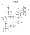
- Figure 1 shows, in a schematic view, the compensation circuit according to the cited patent of the prior art.
- the oscillator symbolically represented by block 9, consists, in a known manner, of a feedback loop comprising a piezoelectric crystal 1, and an amplifier 2, two capacitive elements C 1 and Cv determining, with the crystal, the frequency of oscillation per reaction.
- One of the capacitors Cv is of the type known under the name of varicap, and its value varies according to the value of a direct voltage applied to its terminals, represented in the figure in 7 'and 8'.
- the control voltages of this capacitor are created at its terminals by the outputs 7 and 8 of the compensation circuit whose output 8 delivers a voltage as a variable as a function of the temperature, the voltage e 7 of the output 7 being of constant value, and created by the dividing bridge 10 framed in dashes.
- the potential difference, (e 8 - e 7 ) between outputs 8 and 7 modifies the value of the capacitance of the varicap type capacitor, and therefore, for suitable values of the elements of the compensation network, can compensate for variations in the frequency delivered by the crystal oscillator as a function of the temperature.
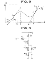
- FIG. 2 represents, according to a diagram in rectangular axes, the curve of variation of the compensation voltage as a function of the temperature supplied by the circuit of the known art of FIG. 1.
- This curve where the temperatures are plotted on the abscissa and the compensation voltages on the ordinate, presents, towards the two ends of the temperature range, two inflection points Pl, P2, below and beyond which it is no longer possible to get the compensation, the necessary curve arcs A 1 , A 2 being replaced by the curve arcs B 1 B 2 .
- FIG. 3 represents, in a partial schematic view, the complementary compensation circuit according to the invention.
- the circuit comprises, with respect to the divider bridge R 12 R 13 of FIG. 1, two thermistors RT 4 and RT 5 in series in the branch of R 13 connected to the negative terminal of the electric power supply source, l one of the two RT 5 thermistors being shunted by a resistor R 14 .
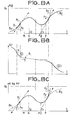
- Figure 4 shows, in two parts (a) and (b), two explanatory drawings of operation at low and high temperatures.
- the circuit can therefore be represented as in (a), where the blocks 12 and 13 represent the elements which are not variable as a function of the temperature.
- the value of the RT 4 thermistor is negligible compared to the value of the other elements of the circuit.
- the circuit can therefore be represented as in (b), where blocks 12 and 15 represent the non-variable elements as a function of the temperature.
- the limit values for RT 5 respectively infinite and zero give the limits of variation of the voltage e 7 .
- FIG. 6 represents, according to three diagrams (a) (b) (c) in rectangular axes, the variations of the final compensation voltage (c), by comparison with the curves (a) (b) of respectively main and complementary compensation .
- the curve (a) is similar to that of FIG. 2, and is that of the compensation voltage e 8 supplied by the circuit of the main patent.
- the curve (b) is that of the compensation voltage e 7 which is supplied by the complementary compensation circuit of FIG. 3.
- This curve includes the extreme arcs which have been described above, arranged on either side of the central part, where the circuit of Figure 3 has very little influence; its only influence is manifested only by a slope a of the curve, in the direction of decreases towards high temperatures.
- Curve (c) represents the final compensation voltage (eg - e 7 ) applied to the "varicap" type capacitor of the oscillator.
- This tension e is represented graphically, to a constant length, by the length of the segment GH determined on a vertical line, by the intersection with the two curves (a) and (b). It can be seen that curve (c) no longer has inflection points at the ends of the temperature range and that its centers of curvature are always there on the same side of the tangent. The overall compensation curve therefore satisfies the indi quées above for the extension of the temperature range where compensation is ensured.
- the temperature range where compensation is ensured then extends for compensation a + 1.10 -6 of the frequency from - 55 0 to + 105 0 .
- FIG. 7 represents a particularly advantageous alternative embodiment of the complementary compensation circuit which is the subject of the present invention.
- the results obtained by this circuit can be observed on the diagram in rectangular axes of figure 8.
- the complementary compensation circuit of FIG. 3 creates, as indicated above, a slope of low value in the middle part of the curve of the compensation voltages represented in FIG. 6, which in certain applications is at to avoid.
- FIG. 8 represents, in rectangular axes, the curve A of the complementary compensation voltage e 7 obtained, as a function of the temperatures at the terminals of the inverted circuit of FIG. 7. It can be noted there that, with respect to the corresponding curve B shown, in dashes obtained with the embodiment of Figure 3, the slope a of the curve in the middle part 81 is replaced by a slightly wavy part 82, which advantageously approaches a more favorable horizontal bearing in certain uses.
- FIG. 10 shows the best exemplary embodiment of a compensation circuit according to the invention, giving the results shown in FIG. 8.
- the circuit shown in this figure compared to that shown in Figure 7, has the following modifications: the resistors R 9 and R 19 have been eliminated while the resistors R 8 and R 18 have been short-circuited.
- the resistors R 41 and R 40 were respectively introduced between the common point on the one hand to the resistors R 7 , RT 3 and R 5 , RT 2 , and on the other hand to the common point to the resistors R 17 , RT 6 and RT 5 , R15. In this way, results are obtained which are superior to those of the circuit shown in FIG. 7, with the aim of stabilizing the frequency of the oscillations in a wide temperature range.
Landscapes
- Oscillators With Electromechanical Resonators (AREA)
Applications Claiming Priority (2)
| Application Number | Priority Date | Filing Date | Title |
|---|---|---|---|
| FR8003979 | 1980-02-22 | ||
| FR8003979A FR2476934A1 (fr) | 1980-02-22 | 1980-02-22 | Oscillateur a cristal compense en temperature. |
Publications (1)
| Publication Number | Publication Date |
|---|---|
| EP0035418A1 true EP0035418A1 (fr) | 1981-09-09 |
Family
ID=9238885
Family Applications (1)
| Application Number | Title | Priority Date | Filing Date |
|---|---|---|---|
| EP81400162A Withdrawn EP0035418A1 (fr) | 1980-02-22 | 1981-02-03 | Oscillateur à cristal compensé en température |
Country Status (4)
| Country | Link |
|---|---|
| US (1) | US4412188A (enExample) |
| EP (1) | EP0035418A1 (enExample) |
| JP (1) | JPS56132001A (enExample) |
| FR (1) | FR2476934A1 (enExample) |
Cited By (1)
| Publication number | Priority date | Publication date | Assignee | Title |
|---|---|---|---|---|
| US9454752B2 (en) | 2001-07-10 | 2016-09-27 | Chartoleaux Kg Limited Liability Company | Reload protocol at a transaction processing entity |
Families Citing this family (12)
| Publication number | Priority date | Publication date | Assignee | Title |
|---|---|---|---|---|
| US4587499A (en) * | 1982-06-07 | 1986-05-06 | Toyo Communication Equipment Co., Ltd. | Temperature compensating circuit for oscillator |
| US4492933A (en) * | 1982-07-28 | 1985-01-08 | Motorola, Inc. | Temperature compensation circuit for oscillator with parabolic characteristic |
| SE456944B (sv) * | 1985-06-18 | 1988-11-14 | Icor Ab | Anordning foer maetning av halten av en given gaskomponent i en gasblandning |
| JPH0181018U (enExample) * | 1987-11-18 | 1989-05-31 | ||
| US4978930A (en) * | 1989-07-18 | 1990-12-18 | At&E Corporation | Low voltage VCO temperature compensation |
| FR2721711B1 (fr) * | 1994-06-24 | 1996-07-26 | Gec Alsthom Stein Ind | Dispositif de mesure de la quantité de charbon dans un broyeur à boulets. |
| JP3542886B2 (ja) * | 1997-04-18 | 2004-07-14 | 有限会社バイテックス | 温度補償水晶発振器 |
| US6040744A (en) * | 1997-07-10 | 2000-03-21 | Citizen Watch Co., Ltd. | Temperature-compensated crystal oscillator |
| US6630872B1 (en) * | 2001-07-20 | 2003-10-07 | Cmc Electronics, Inc. | Digital indirectly compensated crystal oscillator |
| US6570461B1 (en) | 2001-11-21 | 2003-05-27 | Cts Corporation | Trim effect compensation circuit |
| WO2005020427A1 (ja) * | 2003-08-21 | 2005-03-03 | Murata Manufacturing Co., Ltd. | 温度補償型圧電発振器、およびこれを備えた電子装置 |
| JP6590791B2 (ja) * | 2014-03-20 | 2019-10-16 | 日本電波工業株式会社 | 電圧制御発振器 |
Citations (1)
| Publication number | Priority date | Publication date | Assignee | Title |
|---|---|---|---|---|
| FR2284219A1 (fr) * | 1974-09-06 | 1976-04-02 | Cepe | Oscillateur a cristal compense en temperature |
Family Cites Families (3)
| Publication number | Priority date | Publication date | Assignee | Title |
|---|---|---|---|---|
| GB1094768A (en) * | 1966-08-16 | 1967-12-13 | Standard Telephones Cables Ltd | Improvements in temperature compensation of crystal oscillators |
| US3397367A (en) * | 1967-01-12 | 1968-08-13 | Motorola Inc | Temperature compensated crystal oscillator |
| US4107629A (en) * | 1977-05-16 | 1978-08-15 | General Electric Company | Temperature compensator for a crystal oscillator |
-
1980
- 1980-02-22 FR FR8003979A patent/FR2476934A1/fr active Granted
-
1981
- 1981-02-03 EP EP81400162A patent/EP0035418A1/fr not_active Withdrawn
- 1981-02-19 JP JP2366481A patent/JPS56132001A/ja active Pending
- 1981-02-20 US US06/236,630 patent/US4412188A/en not_active Expired - Fee Related
Patent Citations (1)
| Publication number | Priority date | Publication date | Assignee | Title |
|---|---|---|---|---|
| FR2284219A1 (fr) * | 1974-09-06 | 1976-04-02 | Cepe | Oscillateur a cristal compense en temperature |
Cited By (1)
| Publication number | Priority date | Publication date | Assignee | Title |
|---|---|---|---|---|
| US9454752B2 (en) | 2001-07-10 | 2016-09-27 | Chartoleaux Kg Limited Liability Company | Reload protocol at a transaction processing entity |
Also Published As
| Publication number | Publication date |
|---|---|
| FR2476934B1 (enExample) | 1985-05-17 |
| JPS56132001A (en) | 1981-10-16 |
| FR2476934A1 (fr) | 1981-08-28 |
| US4412188A (en) | 1983-10-25 |
Similar Documents
| Publication | Publication Date | Title |
|---|---|---|
| EP0035418A1 (fr) | Oscillateur à cristal compensé en température | |
| EP0190613A1 (fr) | Discriminateur hyperfréquences et dispositif d'utilisation | |
| CA1294336C (fr) | Oscillateur piezoelectrique compense en temperature | |
| EP0660512A1 (fr) | Amplificateur déphaseur et son application à un circuit recombineur | |
| EP0230693B1 (fr) | Etage amplificateur différentiel pour hautes fréquences et amplificateur muni d'un tel étage amplificateur différentiel | |
| EP0859458B1 (fr) | Circuit de modulation de fréquence d'un oscillateur à quartz | |
| FR2584207A1 (fr) | Circuit de commande pour un organe de reglage piezoelectrique | |
| EP0157697B1 (fr) | Oscillateur piézo-électrique fonctionnant en mode apériodique | |
| FR2458942A1 (fr) | Disposition de circuit apte a compenser les variations de frequence, en fonction des variations de temperature, d'un oscillateur a quartz | |
| FR2798780A1 (fr) | Procede et dispositif de controle de la puissance optique d'un emetteur laser | |
| FR2579045A1 (fr) | Transducteur optoelectronique | |
| EP0133388A1 (fr) | Générateur de fréquence compensé en température | |
| FR2581275A1 (fr) | Recepteur de signaux optiques a tres large bande. | |
| EP0201964A1 (fr) | Amplificateur pour hautes fréquences | |
| FR2490895A1 (fr) | Circuit d'entretien pour oscillateur a faible consommation de courant | |
| EP3653019B1 (fr) | Dispositif de regeneration de composants electroniques en environnement nucleaire | |
| EP2076960B1 (fr) | Oscillateur hyperfréquence en technologie des circuits intégrés | |
| EP0050583B1 (fr) | Convertisseur d'une tension alternative en un courant continu et circuit d'oscillateur comportant ce convertisseur | |
| EP0120756A1 (fr) | Oscillateur comprenant un amplificateur passe-bande haute-fréquence à impédance adaptable | |
| WO1992006538A1 (fr) | Oscillateur a cristal compense en temperature | |
| FR2777139A1 (fr) | Oscillateur a frequence controlee en courant, a reponse rapide | |
| EP0113264A1 (fr) | Oscillateur haute fréquence à défaut d'isochronisme compensé | |
| FR2738422A1 (fr) | Circuit de polarisation destine a fixer le niveau moyen d'une tension alternative | |
| EP0716503A1 (fr) | Amplificateur à taux de distorsion réduit | |
| EP0532400A1 (fr) | Discriminateur de fréquence tronqué |
Legal Events
| Date | Code | Title | Description |
|---|---|---|---|
| PUAI | Public reference made under article 153(3) epc to a published international application that has entered the european phase |
Free format text: ORIGINAL CODE: 0009012 |
|
| AK | Designated contracting states |
Designated state(s): CH DE GB IT LI NL SE |
|
| 17P | Request for examination filed |
Effective date: 19820206 |
|
| RAP1 | Party data changed (applicant data changed or rights of an application transferred) |
Owner name: COMPAGNIE D'ELECTRONIQUE ET DE PIEZO-ELECTRICITE - |
|
| STAA | Information on the status of an ep patent application or granted ep patent |
Free format text: STATUS: THE APPLICATION IS DEEMED TO BE WITHDRAWN |
|
| 18D | Application deemed to be withdrawn |
Effective date: 19840109 |
|
| RIN1 | Information on inventor provided before grant (corrected) |
Inventor name: CARET, GUY Inventor name: HELLE, JACQUES |