EP0035034B1 - Process and apparatus for rapid annealing of refractory fiber bodies - Google Patents
Process and apparatus for rapid annealing of refractory fiber bodies Download PDFInfo
- Publication number
- EP0035034B1 EP0035034B1 EP80901841A EP80901841A EP0035034B1 EP 0035034 B1 EP0035034 B1 EP 0035034B1 EP 80901841 A EP80901841 A EP 80901841A EP 80901841 A EP80901841 A EP 80901841A EP 0035034 B1 EP0035034 B1 EP 0035034B1
- Authority
- EP
- European Patent Office
- Prior art keywords
- annealing
- segments
- air
- space
- belt
- Prior art date
- Legal status (The legal status is an assumption and is not a legal conclusion. Google has not performed a legal analysis and makes no representation as to the accuracy of the status listed.)
- Expired
Links
- 238000000137 annealing Methods 0.000 title claims abstract description 121
- 239000000835 fiber Substances 0.000 title claims abstract description 84
- 238000000034 method Methods 0.000 title claims abstract description 43
- 230000008569 process Effects 0.000 title claims abstract description 42
- 239000003570 air Substances 0.000 claims description 84
- 238000009825 accumulation Methods 0.000 claims description 14
- 238000001816 cooling Methods 0.000 claims description 7
- OKTJSMMVPCPJKN-UHFFFAOYSA-N Carbon Chemical compound [C] OKTJSMMVPCPJKN-UHFFFAOYSA-N 0.000 claims description 3
- 239000012080 ambient air Substances 0.000 claims description 3
- 229910052799 carbon Inorganic materials 0.000 claims description 2
- 230000003628 erosive effect Effects 0.000 claims description 2
- 230000001105 regulatory effect Effects 0.000 claims 1
- 230000003014 reinforcing effect Effects 0.000 claims 1
- 239000000463 material Substances 0.000 abstract description 17
- 230000000717 retained effect Effects 0.000 abstract 2
- 239000002657 fibrous material Substances 0.000 abstract 1
- VYPSYNLAJGMNEJ-UHFFFAOYSA-N Silicium dioxide Chemical compound O=[Si]=O VYPSYNLAJGMNEJ-UHFFFAOYSA-N 0.000 description 10
- 238000009413 insulation Methods 0.000 description 8
- 238000004519 manufacturing process Methods 0.000 description 6
- PNEYBMLMFCGWSK-UHFFFAOYSA-N aluminium oxide Inorganic materials [O-2].[O-2].[O-2].[Al+3].[Al+3] PNEYBMLMFCGWSK-UHFFFAOYSA-N 0.000 description 5
- 230000015572 biosynthetic process Effects 0.000 description 5
- 239000002184 metal Substances 0.000 description 5
- 239000000377 silicon dioxide Substances 0.000 description 5
- 230000009471 action Effects 0.000 description 4
- 230000008602 contraction Effects 0.000 description 4
- 230000000694 effects Effects 0.000 description 3
- 239000000203 mixture Substances 0.000 description 3
- 230000002829 reductive effect Effects 0.000 description 3
- XLYOFNOQVPJJNP-UHFFFAOYSA-N water Substances O XLYOFNOQVPJJNP-UHFFFAOYSA-N 0.000 description 3
- 230000002238 attenuated effect Effects 0.000 description 2
- 230000006835 compression Effects 0.000 description 2
- 238000007906 compression Methods 0.000 description 2
- 238000005265 energy consumption Methods 0.000 description 2
- 238000009434 installation Methods 0.000 description 2
- 239000000155 melt Substances 0.000 description 2
- 238000007789 sealing Methods 0.000 description 2
- 241001676573 Minium Species 0.000 description 1
- 230000008859 change Effects 0.000 description 1
- 238000002485 combustion reaction Methods 0.000 description 1
- 239000002131 composite material Substances 0.000 description 1
- 238000010276 construction Methods 0.000 description 1
- 238000010924 continuous production Methods 0.000 description 1
- 238000007796 conventional method Methods 0.000 description 1
- 239000000498 cooling water Substances 0.000 description 1
- 238000005520 cutting process Methods 0.000 description 1
- 238000013461 design Methods 0.000 description 1
- 238000007599 discharging Methods 0.000 description 1
- 238000007380 fibre production Methods 0.000 description 1
- 229910002804 graphite Inorganic materials 0.000 description 1
- 239000010439 graphite Substances 0.000 description 1
- 238000010438 heat treatment Methods 0.000 description 1
- 229910010272 inorganic material Inorganic materials 0.000 description 1
- 239000011147 inorganic material Substances 0.000 description 1
- 229910052809 inorganic oxide Inorganic materials 0.000 description 1
- 239000012212 insulator Substances 0.000 description 1
- 235000000396 iron Nutrition 0.000 description 1
- 230000001788 irregular Effects 0.000 description 1
- 238000005461 lubrication Methods 0.000 description 1
- 230000007246 mechanism Effects 0.000 description 1
- 239000012778 molding material Substances 0.000 description 1
- 238000000465 moulding Methods 0.000 description 1
- 238000012545 processing Methods 0.000 description 1
- 230000000284 resting effect Effects 0.000 description 1
- 230000002441 reversible effect Effects 0.000 description 1
- 229910001220 stainless steel Inorganic materials 0.000 description 1
- 239000010935 stainless steel Substances 0.000 description 1
- 239000010421 standard material Substances 0.000 description 1
- 238000003860 storage Methods 0.000 description 1
- 238000005728 strengthening Methods 0.000 description 1
- 230000001360 synchronised effect Effects 0.000 description 1
- 238000012546 transfer Methods 0.000 description 1
Images



Classifications
-
- C—CHEMISTRY; METALLURGY
- C04—CEMENTS; CONCRETE; ARTIFICIAL STONE; CERAMICS; REFRACTORIES
- C04B—LIME, MAGNESIA; SLAG; CEMENTS; COMPOSITIONS THEREOF, e.g. MORTARS, CONCRETE OR LIKE BUILDING MATERIALS; ARTIFICIAL STONE; CERAMICS; REFRACTORIES; TREATMENT OF NATURAL STONE
- C04B30/00—Compositions for artificial stone, not containing binders
- C04B30/02—Compositions for artificial stone, not containing binders containing fibrous materials
-
- C—CHEMISTRY; METALLURGY
- C03—GLASS; MINERAL OR SLAG WOOL
- C03B—MANUFACTURE, SHAPING, OR SUPPLEMENTARY PROCESSES
- C03B37/00—Manufacture or treatment of flakes, fibres, or filaments from softened glass, minerals, or slags
- C03B37/10—Non-chemical treatment
- C03B37/14—Re-forming fibres or filaments, i.e. changing their shape
- C03B37/15—Re-forming fibres or filaments, i.e. changing their shape with heat application, e.g. for making optical fibres
-
- Y—GENERAL TAGGING OF NEW TECHNOLOGICAL DEVELOPMENTS; GENERAL TAGGING OF CROSS-SECTIONAL TECHNOLOGIES SPANNING OVER SEVERAL SECTIONS OF THE IPC; TECHNICAL SUBJECTS COVERED BY FORMER USPC CROSS-REFERENCE ART COLLECTIONS [XRACs] AND DIGESTS
- Y10—TECHNICAL SUBJECTS COVERED BY FORMER USPC
- Y10S—TECHNICAL SUBJECTS COVERED BY FORMER USPC CROSS-REFERENCE ART COLLECTIONS [XRACs] AND DIGESTS
- Y10S428/00—Stock material or miscellaneous articles
- Y10S428/92—Fire or heat protection feature
-
- Y—GENERAL TAGGING OF NEW TECHNOLOGICAL DEVELOPMENTS; GENERAL TAGGING OF CROSS-SECTIONAL TECHNOLOGIES SPANNING OVER SEVERAL SECTIONS OF THE IPC; TECHNICAL SUBJECTS COVERED BY FORMER USPC CROSS-REFERENCE ART COLLECTIONS [XRACs] AND DIGESTS
- Y10—TECHNICAL SUBJECTS COVERED BY FORMER USPC
- Y10T—TECHNICAL SUBJECTS COVERED BY FORMER US CLASSIFICATION
- Y10T428/00—Stock material or miscellaneous articles
- Y10T428/24—Structurally defined web or sheet [e.g., overall dimension, etc.]
- Y10T428/24942—Structurally defined web or sheet [e.g., overall dimension, etc.] including components having same physical characteristic in differing degree
Definitions
- Line 88 serves as an exhaust line and is controlled by control damper 90 to exhaust air as required.
- support bars 106 which are attached to the frame 96 by flanges 108. As will be described in conjunction with Fig. 5, these supports bars 106 hold the platens 10 in their proper relationship but allow the platens 10 to expand and contact with temperature fluctuations.
- the heated air is kept at a temperature in the range of from 400° to 760°C, preferably about 425° to 650°C, and more preferably about 480° to 590°C. It is therefore apparent that there is a great deal of heat which must be conserved by minimizing the heat transfer to the ambient surroundings. Also, the temperature fluctuations between the closed and heated condition of the annealing phase and the open condition of the transport phase result in significant expansion and contraction of the metal parts of the annealing unit 4. It is therefore important that all the various ducts, blowers, dampers and other components in the air circulation lines be properly insulated. It is also important that the annealing unit 4 itself be adequately insulated and that provisions be made in annealing unit 4 for repeated expansion and contraction of the various metal components.
- the outer support structure consists of hollow structural members 124 (shown in section) to which are attached flanges 126. Flanges 126 have attached thereto insulating bearing material 128 which in turn supports bars 106 attached to the frame 96 of platens 10. Spaces 130 are provided to allow for the expansion of the platens 10 and the resulting movement of bars 106. Similarly, spaces 132 are provided such that when the platens 10 are fully expanded the outermost of the rails 12 are closely adjacent to the edge of seals 134.
- Roller 162 now turns faster than roller 158 and thus in cooperation with the retraction of piston rod 168 causes the catenary 164 to be reduced and all of the accumulated material to be fed into the annealing zone 114 as portion 3.
- the size of accumulator 34 and the speed at which rollers 158, 160 and 162 and piston rod 168 and piston 169 operate will be synchronized with the annealing unit such that a predetermined portion 3 will be fed into the annealing zone in each cycle.
- the outlet accumulation zone 26 is illustrated schematically in Fig. 4.
- the outlet accumulator is an inclined belt accumulator 28 capable of handling either relatively rigid "board" products or relatively flexible “blanket” products.
- a principal component of accumulator 28 is conveyor belt 176.
- Belt 176 runs around fixed rollers 178 and 179 and movable rollers 182 and 184, the latter being attached to piston 180 which operates in cylinder 186.
- the function of the outlet accumulation zone 26 is to accept the annealed portions 3 which are received seriatim as indicated at arrow 188 and discharge the body 2 continuously to conveyor 190 as indicated by arrow 192 so that a continuous feed to slitting, cutting or other subsequent handling operations will be maintained. This is necessary when a blanket product is being made. When a board product is being made, however, the normal use of knife 32 to cut the boards into specific lengths does not require continuous feed and therefore the outlet accumulator operates in a different manner.
- the unit is supported by frame 198 which has the shape of an inverted U.
- Roller 182 is journaled at each end in the upright side members of frame 198 and is free to travel vertically in frame 198.
- Roller 182 is kept level by means of mechanical drive system 196 which acts through a shaft 195 and a sprocket 194 at each side of frame 198.
- mechanical drive system 196 acts through a shaft 195 and a sprocket 194 at each side of frame 198.
- each of the side members of the U-shaped frame 198 contains equipment such as a sprocket 194 which is paired with an identical and cooperating component on the opposite side member.
- the paired components will be referred to and illustrated in Fig. 4 as single devices since only one side of the symmetrical frame 198 is shown.
- the piston 180 When a board product is being made the piston 180 is fully retracted to pull belt 176 taut across pulley 184" and the roller 182 is fully lowered to position 182" such that the belt 176 is horizontal as indicated at 176".
- the inflexible board products can then be moved across the belt 176 on conveyors 190 and 191 to be severed by knife 32.
- the severed portion moves away by conveyor means not shown for further handling while the remainder stays fixed in position until the beginning of the next transport phase.
- the apparatus remains in the same position and does not raise or lower during board production.
- inlet and outlet accumulation zones have been illustrated with the preferred form of accumulator in each, it will be understood that the two types of accumulators may be interchanged or that either or both may be replaced by other accumulation devices with equivalent functions.
- Typical air pressure as measured immediately downstream from damper 74 will be up to approximately 6 inches of water and typical air pressure immediately downstream from damper 64 will be up to approximately 17 inches of water vacuum during the annealing cycle. Pressures may vary from these values with the end object, of course, being the most efficient flow of air through the portion 3. Unduly low air flow will extend the annealing phase time to an undesirable length. Those skilled in the art will be readily able to adjust the appropriate air pressures at given points in a particular system to provide for the optimum flow of air through a given thickness of material in a predetermined time. In the optional air transport phase of the operating cycle the pressure will typically be approximately 2,54 nm of water in line 86 downstream from damper 82. Any reasonable small amount of vacuum can be used in line 58 to draw hot air out of the hood.
- hollow air conduits 420 formed of longitudinal support blocks 418 and lateral support blocks 422.
- the support blocks are shaped and abutted to form a substantially air tight conduit for air passing from inlet plenum 306 through portion 303 and into outlet plenum 308 as indicated by arrows 316, 317 and 318.
- biasing means 424 e.g., springs
- Carbon is the preferred material to make the support blocks from, since it will provide continuous lubrication of the sliding metal belts.
- Movement of the blanket or body 302 is continual, such that an un-annealed portion 303' is always entering zone 314 (as indicated by arrow 426) while a portion 303 is being annealed in zone 314 and fully annealed material is exiting (as indicated by arrow 428).
Landscapes
- Chemical & Material Sciences (AREA)
- Engineering & Computer Science (AREA)
- Organic Chemistry (AREA)
- Ceramic Engineering (AREA)
- Materials Engineering (AREA)
- Life Sciences & Earth Sciences (AREA)
- Structural Engineering (AREA)
- General Life Sciences & Earth Sciences (AREA)
- Geochemistry & Mineralogy (AREA)
- Manufacturing & Machinery (AREA)
- Heat Treatment Of Strip Materials And Filament Materials (AREA)
- Treatment Of Fiber Materials (AREA)
- Inorganic Fibers (AREA)
- Nonwoven Fabrics (AREA)
Abstract
Description
- The invention herein relates to the manufacture of high temperature resistant bodies of refractory fiber. More particularly, it relates to methods of annealing such bodies.
- Refractory fibers are inorganic materials formed from melts composed of inorganic oxides, predominantly alumina and/or silica. In the conventional method of forming refractory fibers, a mixture of oxides is melted and attenuated into elongated fibers. The fibers are collected on a moving belt in the form of a low density, fluffy, continuous, blanket-like body. Thereafter the collected body of fibers can be used as a bulk fiber source, reformed into a denser mat or blanket, or broken up to form short length fibers for use in molding processes. The high temperature resistance of the refractory fiber products makes them extremely valuable for use as thermal insulation in high temperature environments such as furnaces, kilns, ovens and numerous other high temperature applications where bulk or formed insulation is required. When the original oxide mixture is formed almost entirely of generally equal amounts of silica and alumina, the resulting fibers normally are resistant to temperatures up to about 1315°C. Addition of up to 10 to 20 percent by weight of other oxides in different combinations to the basic alumina/silica mixture can produce fibers of differing degrees of thermal resistance. Variation of the ratios of silica and alumina will also affect the thermal resistance, with those fibers having greater proportions of alumina being more thermally resistant than the fibers having higher proportions of silica. Commercial fibers are available for service in the range of from 650°C up to approximately 1650°C.
- When the fibrous blanket is formed, the fibers lay down in a straight, non-interlocking configuration. Thus, the raw blanket is relatively weak and difficult to handle. Various mechanical means are used to cause strengthening by interlocking of fibers. One such means is the use of unthreaded barbed needles which force a number of fibers vertically through the blanket. However, the increase in strength which can be obtained by such mechanical means is rather limited.
- Further, the use of mechanical needling does not yield blankets of good dimensional precision. Fibrous insulating blankets are normally sold on the basis of their thickness and density, which together indicate the thermal resistance properties of the blankets. Mechanical needling usually produces blankets which may have dimensional variations of 25% or more from the desired nominal thickness. Since the quantity of fibers incorporated in the blanket per unit length is controlled on the basis of nominal thickness, the variation in thickness also causes a density variation and thus a variation from the desired thermal properties. It is known that the initial attenuated fiber is formed with differential residual stress present throughout the fiber. It is also known that an elevated temperature stress relief will cause differential relief of these stresses causing the stress relieved fiber to curl. Such a heat treatment results in effective and thorough interlocking of the curled fibers throughout the blanket cross section resulting in quite effective strenthening of the blanket. The heat treated blanket is thus quite capable of being readily handled and installed in normal thermal insulation applications.
- In the past it has been the practice to stress relieve the fibers by annealing the refractory fiber blankets in an oven. Typically, this is accomplished by slowly moving the refractory fiber blankets through a long heated tunnel where each is continuously exposed to a high temperature environment. Conventionally, such annealing requires a minimum of at least about 5 minutes in the oven and more commonly requires a half hour or more.
- There are significant disadvantages and problems with conventional heat soak annealing. The long time periods required seriously reduce the amount of annealed fiber production which can be obtained unless extremely long heat soak tunnels are used to compensate for the long residence time. Use of long tunnels, however, raises the problem of high cost and substantial space requirements. Further, in the heat soak tunnel environment there are usually no restraints on the blankets so that the annealing process can result in dimensional distortion of the blankets within the tunnel. Since such finished annealed blankets therefore would have irregular dimensions, their subsequent installation in company with other annealed blankets in an oven or similar device is seriously complicated, for the installer must take into account the unique dimensional irregularities of such individual blankets.
- In addition, the heat soak tunnels require the use of large amounts of energy. It would therefore be of significant value to have a process in which refractory fiber bodies such as blankets could be annealed rapidly while yet maintaining and assuring dimensional integrity and reducing energy consumption.
- In a process for the annealing of a body of refractory fiber, the invention is characterized in passing air at a temperature in the range of from 400°C to 760°C through said body for a period of from 5 to 200 seconds while maintaining said body with a predetermined dimension in the direction of air flow. In preferred embodiments the process includes use of temperatures in the range of from 425°C to 650°C and intermittent feeding of refractory fiber bodies seriatim into and out of an annealing zone.
- The invention also comprises apparatus for annealing a body of refractory fiber characterized by a pair of spaced apart foraminous supporting means with opposed parallel faces thus defining a space therebetween, means for passing heated air through and from one of said forminous supporting means to and through the other foraminous supporting means and means for inserting segments of said body seriatim into the space between the pair of supporting means and for keeping said segments in said space for said period of 5 to 200 seconds with the opposed faces being in contact with the surfaces of said segments, such that the heated air passes from said one supporting means to said other supporting means also passes through said segment between the pair of supporting means for annealing said segment.
- The invention as claimed enables a rapid annealing of refractory fiber bodies such as blankets while yet maintaining and assuring dimensional integrity and reducing energy consumption.
- Ways of carrying out the invention are described in detail below with reference to drawings.
- Figs. 1 a and 1 together comprise a side elevation view of an annealing production line embodying the process and apparatus of the present invention.
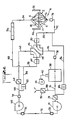
- Figs. 2a and 2b are schematic views illustrating the flow of heated air during the portion of a production cycle when a fiber body is being annealed (fig. 2a) and during the remainder of the production cycle when fiber bodies are being moved into or out of the annealing zone.
- Fig. 3 is a schematic side elevation view of a catenary belt accumulator useful in the present invention.
- Fig. 4 is a schematic view of an inclined plane accumulator useful in the present invention.
- Fig. 5 is a fragmentary elevation view partially in section of the inlet or outlet region of the annealing apparatus.
- Fig. 6 is a fragmentary elevation view partially in section of the side seal apparatus of the present invention.
- Fig. 7 is a fragmentary perspective view of a platen of the present invention.
- Fig. 8 is an end elevation view of the annealing apparatus of the present invention.
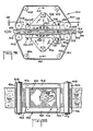
- Fig. 9 is a side elevation view, partially cut away, of a alternative apparatus for carrying out the process of this invention.
- Fig. 10 is a sectional plan view, partially cut away, of the apparatus of Fig. 9 taken on line 10-10.
- The overall operation of the process and the apparatus used therein are best illustrated in the drawings. The preferred embodiment of the apparatus is generally illustrated in the two
parts - The source may also include other apparatus which acts on the fiber body, such as a mechanical needler. The needler is optional, for the annealing process of this invention has been found to produce sufficiently accurate dimensioning of the blanket thickness that needling may be greatly reduced and often eliminated entirely. Some needling may be advantageous, however, as a means of incorporating holes into the blanket which can aid in distributing the annealing air through the blanket during the process of this invention and thus reduce annealing time.
- Further, the "source" may actually be a plurality of sources. Thus, for instance, it is possible to form one layer of fibers on a conveyor belt and thereafter form one or more successive layers of the same or different types of fibers on top of the initial layer. The multilayer blanket can then be rapidly and securely interlocked by the annealing process of this invention into a unitary body. It is thus quite feasible to form, for instance, a composite blanket with an expensive high temperature resistant fiber in a thin layer on the hot face side backed up with a thicker layer of less expensive lower service temperature fiber on the cold face side.
- The
body 2 is normally in the form of a blanket-like strip having dimensions commonly of 7 to 30 cm in thickness and 60 to 250 cm in width. (The length, of course, will be as long as desired, since the blanket will usually be unwound from rolls or fed continuously from the formation chamber). These dimensions are not critical, however, and the present invention is equally capable of annealing fiber bodies having other thickness and/or width dimensions. Further, although the process and apparatus will be described herein in terms of a continuous strip body of fiber to be annealed, since that is the most convenient form in which thefiber body 2 is supplied to the process and apparatus of this invention, it will be understood that thefiber body 2 need not be longitudinally continuous but may be cut into shorter lengths, as long as the minium length is sufficiently longer than the length dimension of the annealing zone so that effective heat sealing at the inlet and outlet ends of the annealing zone is obtained (as will be described below). Division of thebody 2 into discrete lengths prior to annealing is not preferred, however, for it complicates the problems of annealing the fiber near the cut ends. Consequently it is preferred that the feed to the process and apparatus of this invention be in the form of a substantiallycontinuous fiber body 2, and in the remainder of this specification the description will be written with reference to such acontinuous fiber body 2. (Since the portion of thefiber body 2 which is actually being annealed in each cycle of the process is of importance in this process, it will be separately designated as portion orsegment 3 in this specification. It will be understood, however, that theportion 3 is not normally physically separated from body 2). - The
fiber body 2 received from the furnace section of the line or from storage rolls passes first overinlet accumulation zone 33 which as exemplified comprises acatenary belt accumulator 34 which containsconveyor belt 36. The function ofinlet accumulation zone 33 is to accept thefiber body 2 on a continuous basis and convert the continuous motion into intermittent motion to feed the material seriatim into theannealing zone 14 ofannealing unit 4. - The primary device in the apparatus of this system is annealing
unit 4. In the preferred embodiment shown in Figs. 1 through 8, annealingunit 4 is composed of three major components:air inlet plenum 6,air outlet plenum 8 and platens 10 (which when dealt with separately will be designated 1 OU and 10L for the upper and lower platens, respectively). Eachplaten 10 is formed of a plurality of closely spaced and parallel but spaced apart rails 12 which support thefiber blanket portion 3 and through which the heated air can pass. In the embodiment shown in Fig. 1 a the annealing unit is shown open for the non-annealing ("transport") phase of the process. During this phase the annealedportion 3 of thefiber body 2 is being moved out of theannealing zone 14 which lies between the two platens and the next un-annealed portion 3' of thefiber body 2 is being moved into position in theannealing zone 14. Once the un-annealed portion of thebody 2 is in position between the twoplatens 10, the upper platen 10U will be lowered until it makes contact with the upper surface of thenew portion 3 and until it reaches the predetermined distance from a conveyor belt such as 22 lying above the lower platen 1 OL, or, if no belt is used, from thelower platen 10L which corresponds to the desired thickness of the final annealed body. (In actual practice it has been found that theportion 3 should be slightly compressed beyond its nominal desired thickness-e.g., by about 10%-to compensate for the small amount of resiliency in the blanket after annealing, which causes the blanket to expand slightly after leaving the annealing zone 14). Thereafter during the annealing phase of the process, hot air is passed throughplenum 6 as indicated byarrows 16, flows through thelower platen 10L and is forced through theportion 3 of thefiber body 2 withinannealing zone 14, as indicated byarrows 17, and then exhausts through the upper platen 10U andexhaust plenum 8 as indicated byarrows 18. Once the hot air annealing is completed the upper platen is raised and the annealedportion 3 of the fiber body is moved out of theannealing zone 14 and is replaced by another section of un-annealed fiber. - Movement of the
blanket 2 through theannealing zone 14 is preferably accomplished by use ofconveyor 22, which extends through both theannealing zone 14 and thesubsequent cooling section 20.Conveyor 22 is a foraminous belt which is made of a material which can withstand the force and temperature of the hot annealing air flow. An alternative to movement byconveyor 22 is air lifting and pulling of theblanket 2, which will be discussed below. - The annealed fiber is then moved forward to cooling
section 20 byconveyor 22 which carries the annealedbody 2 while it cools. It is possible to allow the annealedbody 2 to cool simply by being exposed to the ambient atmosphere. However, cooling can be materially enhanced by use ofsuction box 24 in which a reduced pressure is maintained and which therefore draws ambient air down and through the annealedbody 2 as it passes over thesuction box 24 in coolingzone 20 onconveyor 22. - The cooled
body 2 then proceeds intooutlet accumulation zone 26 which as exemplified comprises aninclined belt accumulator 28. The function ofzone 26 is to accept the annealedportions 3 of thebody 2 on an intermittent basis and feed the cooled material out to collection devices on a continuous basis. - The
body 2 then feeds pastoptional slitter 30 by which it may be slit longitudinally into strips of desired width and finally passes underknife 32 which severs the strips transversely into segments of desired length. Alternatively, thebody 2, whether or not slit byslitter 30, can be reeled up on a collection roll (not shown) and accumulated for further processing such as chopping of the fiber for molding material. - Figs. 2a and 2b illustrate schematically the operation of the
annealing unit 4. Hot air is generated infurnace 38 which is fed outside air byblower 40 throughline 42. Theblower 40 supplies primarily combustion air which in effect replaces air lost during the different phases of operation. To the greatest extent possible the heated air is recirculated and reheated as required for each cycle in order to conserve energy. It has been found that when properly operated the amount of heated air lost in each cycle is less than 10% of the total; i.e., there is greater than 90% air (and energy) conservation. - For the purposes of this specification, the term "cycle" will refer to an individual segment of the operation of the process from the time at which an un-annealed section 3' of
fiber body 2 begins to enter theannealing zone 14, thus displacing theprevious portion 3 for which annealing has been completed, through the actual annealing of thatnew portion 3 and up until the time at which the annealing unit has re-opened and the now annealedportion 3 is beginning to be conveyed out of theannealing zone 14 and the next un-annealed portion 3' is beginning to enter theannealing zone 14. A cycle consists of two "phases" which will be designated "the annealing phase" and the "transport phase". During the annealing phase theplatens 10 of theannealing unit 14 are "closed", i.e., they are in their closely adjacent locked position with theportion 3 to be annealed between them and with hot air passing through the body. The remainder of the cycle is designated the transport phase during which theplatens 10 are "open" and the fiber body is being moved through theannealing zone 14 to remove the now annealedportion 3 and bring in a non- annealed portion 3' for annealing during the next cycle. - During the annealing phase (Fig. 2a) the hot air from
furnace 38 passes throughline 44 to directingchamber 46. Within directingchamber 46 is directingbaffle 48 which can be aligned as shown in Figs. 2a and 2b to direct the flow of air to or away from theannealing unit 4. During the annealing phase thebaffle 48 is aligned as shown in Fig. 2a and the hot air passing throughdirection chamber 46 passes on throughdamper 50 andline 52 to theinlet plenum 6 ofannealing unit 4. The air under pressure passes throughbody 2 and exhausts throughexhaust plenum 8 intoline 54. From here it passes throughflexible duct 56,line 58 anddamper 60 back todirection chamber 46, from which it is directed throughline 62,control damper 64 andline 66 tofan 68.Fan 68 serves to move the required volume of air and could if necessary be used to restore the pressure entirely to what is needed for the annealing phase. However, because of the high pressure drop across thedense blanket portion 3 it is preferred to use a pair offans line 72 to generate the necessary air pressure. A single high speed blower could be used in place of the twofans fan 70 passes throughcontrol damper 74 andline 76 to return tofurnace 38 where it is reheated and recirculated for the balance of the annealing phase. (In both Figs. 2a and 2b the numeral 78 indicates conventional high temperature expansion joints used in the duct work to compensate for expansion and contraction of the ducts due to temperature fluctuations).Line 88 serves as an exhaust line and is controlled bycontrol damper 90 to exhaust air as required. - At the termination of the annealing phase the hot air stream must be diverted from the
annealing unit 4 so that annealingunit 4 can be opened and the annealedbody 3 moved out ofannealing zone 14 and an un-annealed portion 3' moved into theannealing zone 14. To accomplish this, dampers 50 and 60 are closed in the transport phase and baffle 48 indirection unit 46 is aligned as shown in Fig. 2b. The main body of the heated air is therefore circulated around the cycle defined bylines exhaust plenum 8, andlines plenum 8 into the ambient surroundings ofannealing unit 4. This confinement of the hot air to the interior of theunit 4 is aided by the presence ofbaffles 94 mounted closely adjacent to and on either side ofplenums annealing unit 4 are therefore protected to the greatest extent possible from the effects of the heated air within the unit, including that small amount of heated air which may be used to release the annealed portion ofbody 2 for transport. - In the embodiment shown, the
conveyor 22 moves thesegment 3 out of theannealing zone 14 during the transport phase. In an alternative embodiment (not shown)conveyor 22 does not extend intoannealing zone 14 but rather runs only in coolingsection 20. During the transport phase a small quantity of air is bled off throughdamper 82 andline 86 intoline 52 to pass throughinlet plenum 6 as indicated byarrows 92. This small amount of air provides a small positive pressure below the annealedportion 3 ofbody 2 and lifts that annealedportion 3 slightly off of thelower platen 10L so that it may be transported out ofannealing zone 14 by the pulling action of the portions ofblanket 2 moving throughcooling section 20 andoutlet accumulation zone 26. It will be noted from Fig. 2a that during theannealing phase dampers lines annealing zone 14 following a tear is quite difficult because of the equipment structure and the residual heat present in the equipment. - The
expansion joint 56 is a large, flexible duct which is intended to permit theupper plenum 8 to raise and lower to open andclose annealing section 14 and theplatens 10. - A
typical platen 10 is shown in Fig. 7. In the orientation shown in Fig. 7 theparticular platen 10 would be thelower platen 10L, but the design of the platen is such that the upper platen 10U is just an inverted version of the same device. Theplaten 10 is formed of abasic frame 96 which is normally rectangular with a typical length of 2,4 m and a width of 1,2 m. Therectangular frame 96 is hollow and containstransverse support tubes 98 andlongitudinal ribs 100 inter-engaged with thetubes 98. The upper edge of eachrib 100 is cut into a series ofadjacent notches 102 into which are setrails 12. Therails 12 are closely aligned and parallel but havespaces 104 between them for the passage of the hot air through theplaten 10. - Mounted on the sides of
frame 96 aresupport bars 106 which are attached to theframe 96 byflanges 108. As will be described in conjunction with Fig. 5, these supports bars 106 hold theplatens 10 in their proper relationship but allow theplatens 10 to expand and contact with temperature fluctuations. - In the process of this invention the heated air is kept at a temperature in the range of from 400° to 760°C, preferably about 425° to 650°C, and more preferably about 480° to 590°C. It is therefore apparent that there is a great deal of heat which must be conserved by minimizing the heat transfer to the ambient surroundings. Also, the temperature fluctuations between the closed and heated condition of the annealing phase and the open condition of the transport phase result in significant expansion and contraction of the metal parts of the
annealing unit 4. It is therefore important that all the various ducts, blowers, dampers and other components in the air circulation lines be properly insulated. It is also important that theannealing unit 4 itself be adequately insulated and that provisions be made inannealing unit 4 for repeated expansion and contraction of the various metal components. - The provisions for insulation and expansion and contraction are illustrated in Fig. 5. The hot air flow through the
unit 4 is indicated as before byarrows frame 96 is shown in cross section. Theangle irons 110 shown in cross section anchor thebeams 100 to theframe 96 throughflanges 112.Plenum 6 has a hollow wall composed ofinner plate 114 and anouter skin 116 held in place by pins (not shown) welded toinner plate 114, whileexhaust plenum 8 also has a hollow wall composed ofinner plate 118 and anouter skin 120 similarly attached toinner plate 118. The inner plates and outer skins of the walls of the two plenums are spaced apart and the space between them is filled byinsulation 122.Insulation 122 also continues throughout the side of theunit 4 between theplatens 10 and the outer support structure. - The outer support structure consists of hollow structural members 124 (shown in section) to which are attached
flanges 126.Flanges 126 have attached thereto insulatingbearing material 128 which in turn supportsbars 106 attached to theframe 96 ofplatens 10.Spaces 130 are provided to allow for the expansion of theplatens 10 and the resulting movement ofbars 106. Similarly,spaces 132 are provided such that when theplatens 10 are fully expanded the outermost of therails 12 are closely adjacent to the edge ofseals 134. - Each
seal 134 is composed of a facingplate 136 backed up by acorrugated sheet 138 which is attached to channel 140 which in turn is bolted tostructural member 124. The inner surfaces of the facingplates 136 are smoothly polished to facilitate the movement offiber body 2 into and out of theannealing chamber 14. The corrugations ofsheet 138 cooperate with the facingplate 136 to formchannels 142 adjacent to the facingplate 136 through which cooling water may, if desired, be flowed during operation of the equipment to reduce heat loss through the metal seal. Heat loss through the fiber body is prevented by the length of the segment of material present between theseals 134, since the fiber body itself is a highly effective insulator. Air flow into theannealing zone 14 through theblanket 2 from outside the equipment shown in Fig. 5 is essentially prevented by theblanket 2 itself. The air flow path through that portion of theblanket 2 between plates 136'is so long and tortuous that essentially no air passes through this blanket portion during the short time of each annealing phase. - Fig. 6 illustrates the provision for thermal sealing of the longitudinal edges of the
unit 4. Theedges 144 of theportion 3 ofbody 2 being annealed are compressed by means ofbar 146 to a high density such that air flow through eachedge 144 from theexterior space 145 into theannealing zone 14 is minimized (and preferably essentially eliminated).Bar 146 is held in place bybolts 152 which are secured by the wedging action ofmembers wedge clamp member 148. The compressed edge is subsequently trimmed off as byslitter 30. (Also shown in Fig. 6 areclamps 156 which attach theplaten 10 to frame 96 through tubes 98). - The degree of compression of the blanket is controlled by
member 154. The thickness of theblanket portion 3 is sized to different thicknesses by addition or removal of one or more of theshims 157 at the bottom ofmember 154. Typical shims vary in thickness from 0,4 mm to 51 mm and are used in the appropriate combination to produce the desired blanket thickness. - The
inlet accumulation zone 33 is shown schematically in Fig. 3. The preferredcatenary belt accumulator 34 is composed of anendless conveyor belt 36 which passes over poweredinlet end roller 158, one or moreidler rollers 160 and poweredoutlet end roller 162. It is constructed with extra length so that catenaries can be formed between each adjacent roller, as indicated at 164. This formation of the catenaries is controlled byrollers pulley roller 166 which is connected topiston rod 168 andpiston 169 which operate incylinder 170. The function of theinlet accumulation zone 33 is to receive thefiber body 2 continuously from the supply source as indicated byarrow 172 and to feed the body intermittently to theannealing zone 14 as indicated byarrow 174. At the start of the annealing phase of a cycle theconveyor belt 36 will be essentially in the position shown by the solid line in Fig. 3.Roller 162 will be stopped and locked against rotation.Roller 158 will, however, be turning down at a constant speed as bymotor 159 and drive belt 161. Thus as thecontinuous body 2 enters theaccumulator 34piston rod 168 will slowly extend allowingroller 158 to create thecatenary 164 and thus take up the entire quantity of thefiber body 2 received during the period of that annealing phase even though none of thefiber body 2 is being discharged pastroller 162. The motion ofroller 158 as it feedsbelt 36 into thecatenaries 164 also causesroller 166 to extendpiston rod 168.Piston 169 thus moves withincylinder 170, causing the air trapped incylinder 170 to flow through pipe 171 toair tank 173, where the air pressure increases to a predetermined level. Make-up air as needed is provided throughvalve 175 andline 177. Accumulation can be aided by poweringidler roller 160 during accumulation and then unclutching it during the transport phase. When the annealing phase is completed and the transport phase beginspowered roller 162 is started. The air pressure intank 173 acting againstpiston 169 causes therod 168 to retract thus eliminating thecatenaries 164.Roller 162 now turns faster thanroller 158 and thus in cooperation with the retraction ofpiston rod 168 causes thecatenary 164 to be reduced and all of the accumulated material to be fed into theannealing zone 114 asportion 3. Clearly, of course, the size ofaccumulator 34 and the speed at whichrollers piston rod 168 andpiston 169 operate will be synchronized with the annealing unit such that apredetermined portion 3 will be fed into the annealing zone in each cycle. - The
outlet accumulation zone 26 is illustrated schematically in Fig. 4. In the preferred embodiment illustrated the outlet accumulator is aninclined belt accumulator 28 capable of handling either relatively rigid "board" products or relatively flexible "blanket" products. A principal component ofaccumulator 28 isconveyor belt 176. Belt 176 runs around fixedrollers movable rollers piston 180 which operates incylinder 186. The function of theoutlet accumulation zone 26 is to accept the annealedportions 3 which are received seriatim as indicated atarrow 188 and discharge thebody 2 continuously toconveyor 190 as indicated byarrow 192 so that a continuous feed to slitting, cutting or other subsequent handling operations will be maintained. This is necessary when a blanket product is being made. When a board product is being made, however, the normal use ofknife 32 to cut the boards into specific lengths does not require continuous feed and therefore the outlet accumulator operates in a different manner. - The unit is supported by
frame 198 which has the shape of aninverted U. Roller 182 is journaled at each end in the upright side members offrame 198 and is free to travel vertically inframe 198.Roller 182 is kept level by means ofmechanical drive system 196 which acts through ashaft 195 and asprocket 194 at each side offrame 198. (It will be evident that each of the side members of theU-shaped frame 198 contains equipment such as asprocket 194 which is paired with an identical and cooperating component on the opposite side member. For simplicity herein the paired components will be referred to and illustrated in Fig. 4 as single devices since only one side of thesymmetrical frame 198 is shown. The paired relationship will be understood by those skilled in the art, however). The weights ofroller 182,belt 176 and the conveyed blanket are counterbalanced bycounterweight 202 which is connected to the end ofroller 182 bycable 200. The end ofroller 182 is also connected tocable 216 which is reeved oversprocket 194 andpulley 185,pulley 185 being connected topiston 218 which operates incylinder 220. - When a "blanket" material is being produced, at the start of the transport phase of a cycle the outlet unit is disposed as follows: the belt is at 176', the movable rollers are at 182' and 184', the pulley is at 185' and the counterweight is at 202'. As the transport phase proceeds and material enters
zone 26 as indicated byarrow 188, roller 182' proceeds upward toposition 182 and roller 184' is drawn inward toposition 184, extractingpiston 180 fromcylinder 186 and causing air to be forced throughline 226 intotank 222.Roller 182 is moved upward by the combined action ofdrive unit 196 acting oncable 216 throughsprocket 194 and by the pressure of air from tank 222 (or line 226) passing throughline 224 tocylinder 220 and forcingpiston 218 outward to drive the pulley out toposition 185. At the end of the transport phase the operation reverses, and during the annealling phase, when no material is entering at 188, theroller 182 drops back to position 182', the other components reverse their movement described above, and material is fed smoothly and continuously frombelt 176 ontobelt 190 as indicated byarrow 192 asbelt 176 returns to position 176'.Rollers belt 176 and discharging the accumulated material. Air lost fromtank 222 is replenished as needed from line 228 (which is connected to a source of compressed air not shown). The sequence of operations repeats for every annealing cycle. - When a board product is being made the
piston 180 is fully retracted to pullbelt 176 taut acrosspulley 184" and theroller 182 is fully lowered to position 182" such that thebelt 176 is horizontal as indicated at 176". The inflexible board products can then be moved across thebelt 176 onconveyors knife 32. The severed portion moves away by conveyor means not shown for further handling while the remainder stays fixed in position until the beginning of the next transport phase. The apparatus remains in the same position and does not raise or lower during board production. - Although the inlet and outlet accumulation zones have been illustrated with the preferred form of accumulator in each, it will be understood that the two types of accumulators may be interchanged or that either or both may be replaced by other accumulation devices with equivalent functions.
- Fig. 8 illustrates the operating mechanism that raises and lowers the upper platen 10U to open and close the
annealing zone 14. The lower portion ofunit 4 includingplenum 6 andplaten 10L is supported byframe 204 which is directly fixed tofloor 206. The upper portion ofunit 4 which includesplenum 8 and upper platen 10U is supported by fixedframe 208 which also rests onfloor 206. Supported withinframe 208 ismovable frame 210 which directly supportsplenum 8 and upper platen 10U.Movable frame 210 is connected to fixedframe 208 by piston-and-cylinder units 212, with onesuch unit 212 being mounted at each corner of theframe 210. Mounted centrally offrame 210 is piston-and-cylinder unit 214. As the final part of the transport phase of each cycle, theunit 214 is activated to bias theframe 210 downward, carrying with it platen 10U andplenum 8. The downward movement is continued until a spacing slightly greater than the proper spacing ofplatens 10 is obtained. At thatpoint pistons 212 are activated to provide the final pressure to seal the edges of theportion 3 ofbody 2 to be annealed and to fix theplatens 10 in their proper spaced apart relationship. Upon completion of the annealing phase the operations are reversed withunits 212 being released followed by retraction of theunit 214 to open theannealing zone 14 andplatens 10. - In the process of this invention the typical annealing phase time is from 5 to 200 seconds depending on the thickness of the
portion 3 to be annealed and the temperature of the annealing air. For a fiber body of 2,5 cm nominal thickness and 0,1 g/cm3 nominal density, with annealing air at a temperature of about 540°C, an annealing period of between 10 and 30 seconds has been found to be quite satisfactory. Control of the desired degree of annealing for a given density of blanket is preferably by means of control of the temperature and/or air flow rate of the hot annealing air, while the rate of blanket passage through the annealing zone remains constant. It is possible to use blanket passage rate as a control variable but that is not preferred because it makes the equipment and operations unduly complicated as compared to control by means of air temperature and/or flow rate. - Typical air pressure as measured immediately downstream from
damper 74 will be up to approximately 6 inches of water and typical air pressure immediately downstream fromdamper 64 will be up to approximately 17 inches of water vacuum during the annealing cycle. Pressures may vary from these values with the end object, of course, being the most efficient flow of air through theportion 3. Unduly low air flow will extend the annealing phase time to an undesirable length. Those skilled in the art will be readily able to adjust the appropriate air pressures at given points in a particular system to provide for the optimum flow of air through a given thickness of material in a predetermined time. In the optional air transport phase of the operating cycle the pressure will typically be approximately 2,54 nm of water inline 86 downstream fromdamper 82. Any reasonable small amount of vacuum can be used inline 58 to draw hot air out of the hood. - Figs. 9 and 10 illustrate schematically an alternative annealing zone structure 314 (Components corresponding to those in Figs. 1 through 8 will be designated with like numerals preceded by a "3"). The
annealing unit 304 is composed of two opposed and spaced apart continuousflexible metal belts rollers arrows belts - The
belts outer portions 416 of the belts, which are of sufficient width to accommodatesupport blocks portion 303 ofbody 302. The belts are supported and maintained at the proper spacing by closely spacedidler rollers 430. - Resting on the inner surfaces of
belts hollow air conduits 420 formed of longitudinal support blocks 418 and lateral support blocks 422. The support blocks are shaped and abutted to form a substantially air tight conduit for air passing frominlet plenum 306 throughportion 303 and intooutlet plenum 308 as indicated byarrows - Movement of the blanket or
body 302 is continual, such that an un-annealed portion 303' is always entering zone 314 (as indicated by arrow 426) while aportion 303 is being annealed inzone 314 and fully annealed material is exiting (as indicated by arrow 428). - Because of the various temperatures involved in the different parts of this system and particularly in the annealing unit, materials of construction must be chosen accordingly. Those skilled in the art will be aware of standard materials such as stainless steel grades for the high temperature components and appropriate thermal insulation where designated and can readily determine the appropriate materials to use for any particular installation.
- It will also be immediately recognized that the system lends itself readily to automated control particularly of temperature, pressure and cycle times. Use of microprocessors will also be desirable in conjunction with appropriate sensing devices for the parameters to be controlled.
- The process and apparatus described herein are useful in the manufacture of inorganic refractory fiber bodies, which bodies find extensive industrial use as thermal insulation for ovens, kilns, furnaces and other devices which operate at elevated temperatures and in which it is desired to minimize heat loss and/or prevent heat flow effects to surrounding areas.
Claims (27)
Applications Claiming Priority (2)
| Application Number | Priority Date | Filing Date | Title |
|---|---|---|---|
| US06/073,412 US4294878A (en) | 1979-09-07 | 1979-09-07 | Process for rapid annealing of refractory fiber bodies and laminated body produced by process |
| US73412 | 1998-05-06 |
Publications (3)
| Publication Number | Publication Date |
|---|---|
| EP0035034A1 EP0035034A1 (en) | 1981-09-09 |
| EP0035034A4 EP0035034A4 (en) | 1982-01-11 |
| EP0035034B1 true EP0035034B1 (en) | 1984-06-27 |
Family
ID=22113553
Family Applications (1)
| Application Number | Title | Priority Date | Filing Date |
|---|---|---|---|
| EP80901841A Expired EP0035034B1 (en) | 1979-09-07 | 1981-03-23 | Process and apparatus for rapid annealing of refractory fiber bodies |
Country Status (6)
| Country | Link |
|---|---|
| US (1) | US4294878A (en) |
| EP (1) | EP0035034B1 (en) |
| JP (1) | JPS56501252A (en) |
| CA (1) | CA1172023A (en) |
| DE (1) | DE3068355D1 (en) |
| WO (1) | WO1981000692A1 (en) |
Families Citing this family (16)
| Publication number | Priority date | Publication date | Assignee | Title |
|---|---|---|---|---|
| US4693940A (en) * | 1983-02-14 | 1987-09-15 | Raychem Corporation | Laminate and method of preparing same |
| US4488928A (en) * | 1983-05-16 | 1984-12-18 | Kimberly-Clark Corporation | Method and apparatus for forming soft, bulky absorbent webs and resulting product |
| US4783310A (en) * | 1986-10-27 | 1988-11-08 | The United States Of America As Represented By The United States Department Of Energy | Heat barrier for use in a nuclear reactor facility |
| US4790167A (en) * | 1987-06-23 | 1988-12-13 | Granco-Clark, Inc. | Extrusion run-out table |
| JP3344511B2 (en) * | 1993-12-21 | 2002-11-11 | 東洋紡績株式会社 | Reticulated structure and method for producing the same |
| JP3430442B2 (en) * | 1993-12-21 | 2003-07-28 | 東洋紡績株式会社 | Reticulated structure and method for producing the same |
| JP3344512B2 (en) * | 1993-12-24 | 2002-11-11 | 東洋紡績株式会社 | Heterogeneous net structure and manufacturing method thereof |
| JP3344514B2 (en) * | 1993-12-27 | 2002-11-11 | 東洋紡績株式会社 | Multi-component network structure and manufacturing method thereof |
| JP3314839B2 (en) * | 1993-12-28 | 2002-08-19 | 東洋紡績株式会社 | Heat-adhesive network structure and method for producing the same |
| JPH10503247A (en) * | 1994-07-18 | 1998-03-24 | オウェンス コーニング | Bicomponent and long fiber product formation for splittable packs |
| JPH10503557A (en) * | 1994-07-25 | 1998-03-31 | オウェンス コーニング | Bicomponent and long fiber product formation |
| US7150627B2 (en) * | 2005-04-30 | 2006-12-19 | Siddhartha Gaur | Transported material heating with controlled atmosphere |
| US8517760B2 (en) | 2007-08-20 | 2013-08-27 | Ford Global Technologies, Llc | Cord wrap and power plug receptacle arrangement for inflator |
| US8981921B2 (en) | 2007-09-08 | 2015-03-17 | Ford Global Technologies, Llc | Status indicator and reminder system for vehicle temporary mobility kit |
| US9310132B1 (en) | 2012-02-08 | 2016-04-12 | Carbonyx, Inc. | Replaceable insulation roof for industrial oven |
| CN104487755B (en) | 2012-07-12 | 2017-03-08 | 株式会社Kcc | Comprise the vacuum heat insulation material of the binder free glass fibre of annealing |
Family Cites Families (7)
| Publication number | Priority date | Publication date | Assignee | Title |
|---|---|---|---|---|
| US3485611A (en) * | 1966-05-27 | 1969-12-23 | Babcock & Wilcox Co | Rotary apparatus for making ceramic fibers |
| JPS5231367B1 (en) * | 1969-11-18 | 1977-08-15 | ||
| US3887524A (en) * | 1971-04-06 | 1975-06-03 | Henry P Kirchner | Method of strengthening alumina ceramic by quenching with liquid medium |
| US3792139A (en) * | 1972-08-09 | 1974-02-12 | Us Army | Process for flattening alumina substrates |
| CH596109A5 (en) * | 1975-01-15 | 1978-02-28 | Activite Atom Avance | |
| GB1497808A (en) * | 1975-05-29 | 1978-01-12 | Kroyer St Annes Ltd Karl | Apparatus for dry forming a layer of fibre |
| GB1531167A (en) * | 1976-08-16 | 1978-11-01 | Chloride Silent Power Ltd | Production of beta-alumina |
-
1979
- 1979-09-07 US US06/073,412 patent/US4294878A/en not_active Expired - Lifetime
-
1980
- 1980-09-04 JP JP50218480A patent/JPS56501252A/ja active Pending
- 1980-09-04 DE DE8080901841T patent/DE3068355D1/en not_active Expired
- 1980-09-04 WO PCT/US1980/001178 patent/WO1981000692A1/en not_active Ceased
- 1980-09-08 CA CA000359841A patent/CA1172023A/en not_active Expired
-
1981
- 1981-03-23 EP EP80901841A patent/EP0035034B1/en not_active Expired
Also Published As
| Publication number | Publication date |
|---|---|
| JPS56501252A (en) | 1981-09-03 |
| EP0035034A4 (en) | 1982-01-11 |
| US4294878A (en) | 1981-10-13 |
| EP0035034A1 (en) | 1981-09-09 |
| WO1981000692A1 (en) | 1981-03-19 |
| CA1172023A (en) | 1984-08-07 |
| DE3068355D1 (en) | 1984-08-02 |
Similar Documents
| Publication | Publication Date | Title |
|---|---|---|
| US4294878A (en) | Process for rapid annealing of refractory fiber bodies and laminated body produced by process | |
| US4278624A (en) | Fluid film continuous processing method and apparatus | |
| US3242527A (en) | Oven for curling resin impregnated fibrous mat | |
| CN87107272A (en) | Mineral Fiber Heating Methods | |
| FI121927B (en) | PROCEDURE AND BAND SINTERING SYSTEM FOR CONTINUOUS SINTERING OF PELLETERED MINERAL MATERIAL | |
| EP0468716A2 (en) | Insulating heat retention apparatus | |
| US3940961A (en) | Apparatus for cooling hot rolled steel rod by forced air convection or by supplying heat | |
| CN108327036B (en) | Device and method for discharging chips discharged laterally from a continuous press | |
| SU608466A3 (en) | Arrangement for making fibrous plates | |
| US4416071A (en) | Apparatus for rapid annealing of refractory fiber bodies | |
| FI63071B (en) | ANORDNING FOER VAERMEHAERDNING AV FIBERMATTOR | |
| US2443443A (en) | Apparatus for producing films | |
| US3928105A (en) | Automated apparatus and process for making match molded covering | |
| US3912572A (en) | Method of and apparatus for forming articles of fibrous materials | |
| US2199472A (en) | Method and apparatus for annealing strip | |
| JPH0573664B2 (en) | ||
| CN109228093B (en) | Full-automatic molding press | |
| US2587742A (en) | Apparatus for continuously processing strands | |
| JPS627288B2 (en) | ||
| US4076479A (en) | Apparatus for forming articles of fibrous materials | |
| CN110099783B (en) | Base structure, device and method for transferring foils | |
| US3939022A (en) | Method of forming articles of fibrous materials | |
| JPH0323145A (en) | Device for traction or braking for band- shaped body | |
| JP2026512958A (en) | Method and apparatus for drying strips of adhesive material for the manufacture of smoking products | |
| SU1090577A1 (en) | Installation for continuous manufacture of laminated articles |
Legal Events
| Date | Code | Title | Description |
|---|---|---|---|
| PUAI | Public reference made under article 153(3) epc to a published international application that has entered the european phase |
Free format text: ORIGINAL CODE: 0009012 |
|
| 17P | Request for examination filed |
Effective date: 19810529 |
|
| AK | Designated contracting states |
Designated state(s): DE FR GB |
|
| GRAA | (expected) grant |
Free format text: ORIGINAL CODE: 0009210 |
|
| AK | Designated contracting states |
Designated state(s): DE FR GB |
|
| REF | Corresponds to: |
Ref document number: 3068355 Country of ref document: DE Date of ref document: 19840802 |
|
| PGFP | Annual fee paid to national office [announced via postgrant information from national office to epo] |
Ref country code: FR Payment date: 19840926 Year of fee payment: 5 |
|
| PGFP | Annual fee paid to national office [announced via postgrant information from national office to epo] |
Ref country code: DE Payment date: 19840927 Year of fee payment: 5 |
|
| ET | Fr: translation filed | ||
| PLBE | No opposition filed within time limit |
Free format text: ORIGINAL CODE: 0009261 |
|
| STAA | Information on the status of an ep patent application or granted ep patent |
Free format text: STATUS: NO OPPOSITION FILED WITHIN TIME LIMIT |
|
| 26N | No opposition filed | ||
| PG25 | Lapsed in a contracting state [announced via postgrant information from national office to epo] |
Ref country code: DE Effective date: 19880601 |
|
| GBPC | Gb: european patent ceased through non-payment of renewal fee | ||
| PG25 | Lapsed in a contracting state [announced via postgrant information from national office to epo] |
Ref country code: GB Free format text: LAPSE BECAUSE OF NON-PAYMENT OF DUE FEES Effective date: 19881118 |
|
| PG25 | Lapsed in a contracting state [announced via postgrant information from national office to epo] |
Ref country code: FR Free format text: LAPSE BECAUSE OF NON-PAYMENT OF DUE FEES Effective date: 19890531 |
|
| REG | Reference to a national code |
Ref country code: FR Ref legal event code: ST |