EP0034614B1 - Control system for cheng dual-fluid cycle engine system - Google Patents
Control system for cheng dual-fluid cycle engine system Download PDFInfo
- Publication number
- EP0034614B1 EP0034614B1 EP80901642A EP80901642A EP0034614B1 EP 0034614 B1 EP0034614 B1 EP 0034614B1 EP 80901642 A EP80901642 A EP 80901642A EP 80901642 A EP80901642 A EP 80901642A EP 0034614 B1 EP0034614 B1 EP 0034614B1
- Authority
- EP
- European Patent Office
- Prior art keywords
- engine
- steam
- control
- load
- turbine
- Prior art date
- Legal status (The legal status is an assumption and is not a legal conclusion. Google has not performed a legal analysis and makes no representation as to the accuracy of the status listed.)
- Expired
Links
- 239000012530 fluid Substances 0.000 title claims abstract description 98
- 239000000446 fuel Substances 0.000 claims abstract description 61
- 230000036961 partial effect Effects 0.000 claims abstract description 30
- 238000002485 combustion reaction Methods 0.000 claims abstract description 11
- 239000000203 mixture Substances 0.000 claims description 42
- 238000013461 design Methods 0.000 claims description 38
- 238000000034 method Methods 0.000 claims description 31
- 230000008569 process Effects 0.000 claims description 25
- XLYOFNOQVPJJNP-UHFFFAOYSA-N water Substances O XLYOFNOQVPJJNP-UHFFFAOYSA-N 0.000 claims description 25
- 230000007423 decrease Effects 0.000 claims description 12
- 238000010438 heat treatment Methods 0.000 claims description 9
- 230000002829 reductive effect Effects 0.000 claims description 6
- 239000002918 waste heat Substances 0.000 abstract description 16
- 239000000567 combustion gas Substances 0.000 abstract description 3
- 239000007789 gas Substances 0.000 description 37
- 230000006870 function Effects 0.000 description 23
- 230000001276 controlling effect Effects 0.000 description 11
- 230000004044 response Effects 0.000 description 10
- 230000006835 compression Effects 0.000 description 9
- 238000007906 compression Methods 0.000 description 9
- 230000008859 change Effects 0.000 description 8
- 230000003247 decreasing effect Effects 0.000 description 4
- 238000011084 recovery Methods 0.000 description 4
- 230000001419 dependent effect Effects 0.000 description 3
- 238000002347 injection Methods 0.000 description 3
- 239000007924 injection Substances 0.000 description 3
- 238000012546 transfer Methods 0.000 description 3
- 230000000670 limiting effect Effects 0.000 description 2
- 239000013641 positive control Substances 0.000 description 2
- 230000001360 synchronised effect Effects 0.000 description 2
- 230000002195 synergetic effect Effects 0.000 description 2
- 241000269420 Bufonidae Species 0.000 description 1
- 238000010793 Steam injection (oil industry) Methods 0.000 description 1
- 230000001133 acceleration Effects 0.000 description 1
- 230000009471 action Effects 0.000 description 1
- 230000003321 amplification Effects 0.000 description 1
- 230000003466 anti-cipated effect Effects 0.000 description 1
- 150000001875 compounds Chemical class 0.000 description 1
- 238000012937 correction Methods 0.000 description 1
- 238000010586 diagram Methods 0.000 description 1
- 230000000694 effects Effects 0.000 description 1
- 230000005611 electricity Effects 0.000 description 1
- 238000004146 energy storage Methods 0.000 description 1
- 230000008020 evaporation Effects 0.000 description 1
- 238000001704 evaporation Methods 0.000 description 1
- 230000003993 interaction Effects 0.000 description 1
- 239000007788 liquid Substances 0.000 description 1
- 238000004519 manufacturing process Methods 0.000 description 1
- 230000005055 memory storage Effects 0.000 description 1
- 238000010606 normalization Methods 0.000 description 1
- 238000003199 nucleic acid amplification method Methods 0.000 description 1
- 238000013021 overheating Methods 0.000 description 1
- 238000002360 preparation method Methods 0.000 description 1
- 230000001681 protective effect Effects 0.000 description 1
- 238000005086 pumping Methods 0.000 description 1
- 230000001105 regulatory effect Effects 0.000 description 1
- 239000000523 sample Substances 0.000 description 1
- 238000003860 storage Methods 0.000 description 1
- 230000009469 supplementation Effects 0.000 description 1
- 239000002699 waste material Substances 0.000 description 1
- 239000002351 wastewater Substances 0.000 description 1
Images

Classifications
-
- F—MECHANICAL ENGINEERING; LIGHTING; HEATING; WEAPONS; BLASTING
- F01—MACHINES OR ENGINES IN GENERAL; ENGINE PLANTS IN GENERAL; STEAM ENGINES
- F01K—STEAM ENGINE PLANTS; STEAM ACCUMULATORS; ENGINE PLANTS NOT OTHERWISE PROVIDED FOR; ENGINES USING SPECIAL WORKING FLUIDS OR CYCLES
- F01K21/00—Steam engine plants not otherwise provided for
- F01K21/04—Steam engine plants not otherwise provided for using mixtures of steam and gas; Plants generating or heating steam by bringing water or steam into direct contact with hot gas
- F01K21/047—Steam engine plants not otherwise provided for using mixtures of steam and gas; Plants generating or heating steam by bringing water or steam into direct contact with hot gas having at least one combustion gas turbine
-
- Y—GENERAL TAGGING OF NEW TECHNOLOGICAL DEVELOPMENTS; GENERAL TAGGING OF CROSS-SECTIONAL TECHNOLOGIES SPANNING OVER SEVERAL SECTIONS OF THE IPC; TECHNICAL SUBJECTS COVERED BY FORMER USPC CROSS-REFERENCE ART COLLECTIONS [XRACs] AND DIGESTS
- Y02—TECHNOLOGIES OR APPLICATIONS FOR MITIGATION OR ADAPTATION AGAINST CLIMATE CHANGE
- Y02E—REDUCTION OF GREENHOUSE GAS [GHG] EMISSIONS, RELATED TO ENERGY GENERATION, TRANSMISSION OR DISTRIBUTION
- Y02E20/00—Combustion technologies with mitigation potential
- Y02E20/14—Combined heat and power generation [CHP]
Definitions
- This invention relates to heat engine control systems, and in particular to a control system for a Cheng dual-fluid engine.
- the U.S.-A-4,128,994 defines the peak operating condition cycle parameters to design an engine for 100 percent load. Because of the parallel combined nature of the Brayton and Rankine cycles in this engine, the quantity and quality of steam that can be generated by a given engine configuration can be varied freely over a range.
- the control path for a steam cycle is essentially independent of that for the gas turbine cycle.
- the control path for throttling the engine is essentially free or undefined.
- the waste heat boiler for the dual-fluid engine system is normally designed for the peak efficiency condition at design load.
- the surface area for the heat exchanger is fixed. If one desires to operate the engine at over-load conditions, the required surface area to generate more steam is not available unless the system has been designed with a boiler that is oversized for the design load condition.
- the area of the heat exchanger is in excess of needs, thus permitting operation at decreased differences in exhaust gas and boiler temperature.
- peak work output efficiency of the dual-fluid cycle engine occurs only at a certain steam-to-air ratio. That ratio of steam-to-air is precisely defined as corresponding to maximum recovery of exhaust heat by the steam within designated turbine temperature limits of the engine. Steam is generated by recovering the exhaust waste heat at pressures usually used in a steam Rankine cycle following a gas turbine, the so-called combined gas-steam (COGAS) system.
- COGAS combined gas-steam
- the steam is injected into the engine before the work turbine and both combustion gases and steam deliver work to the turbine. Since the energy of the steam is derived from the exhaust of the same work turbine, or turbines, the system contains a feedback loop which must be solved in designing a control system.
- the Cheng cycle is complicated in other ways. Unlike a gas turbine engine the exhaust temperature of the Cheng cycle turbine at a given inlet temperature and fixed pressure ratio is no longer uniquely defined by the turbine characteristics. It also depends on the steam-air mixture, X mIX' Steam and combustion air have different thermodynamic properties, namely, specific heats, and their ratio. Air has a higher gamma function, i.e., specific heat ratio, than steam. In expanding a mixture of combustion air and steam through a turbine more work is produced for a given pressure ratio expansion than can be produced by expanding the air and the steam separately through the same pressure ratio.
- the maximum heat recovery rate does not occur at the lowest waste heat boiler gas exit temperatures.
- the latent heat of evaporation of the steam in the mixture gas is generally not recovered. Physically, if too much steam is used, the exit (engine injection) temperature of the steam from the waste boiler is low dueto the large amount of water used to recover the waste heat. The heat loss due to the latent heat content of the exhaust gas exiting the boiler is very large. On the other hand, if the steam quantities are insufficient the heat exchanger exit temperatures of the exhaust products become excessive, and the engine will not have reached its improved efficiency potential. For a given set of parametric constraints the peak efficiency occurs at the steam-air ratio corresponding to the maximum rate of waste heat recovery. This is not known unless the constraints on the boiler design are given.
- a prior art control system for utilizing maximum tolerable amounts of steam in gas turbines as described in US ⁇ A ⁇ 3,693,347 adjusts for the load on the gas turbine by varying steam injection; if steam is generated at a substantially constant rate, e.g. by using the exhaust of the turbine, the steam not injected may be diverted to other uses, such as process steam or space heating. To achieve reduced power output but yet operate at maximum steam flow and efficiency it is contemplated to operate the machine at a turbine inlet temperature below the maximum turbine inlet temperature thereof.
- control is accomplished according to the invention by properly adjusting the steam-to-air ratio and air- fuel ratio through a positive control system having independent fuel and steam control loops.
- One of the important features of the subject invention is the linking of all operating parameters at conditions that yield (if only work output is considered) maximum work output efficiency for every partial and overload condition across the entire load range. This becomes then a primary objective of the control system.
- the sets of combinations of engine operating parameters for highest efficiency at each partial load is computed by methods similar to those described in US ⁇ A ⁇ 4,128,994 using engine component specifications and ambient conditions, except that the engine configuration is fixed rather than "rubberized".
- the designer in initially designing the dual-fluid cycle engine, the designer is free to use whatever component sizes he wishes, but once the engine is designed and built, such freedom does not exist when the engine is operated at other than 100% load conditions. Consequently, some of the fixed quantities in the engine design according to US-A-4,128,994 such as temperature differences in the "neck” and "top” of the heat exchanger, become variables in deriving a control scheme while the heat exchanger surface area, which was free to float to any necessary value to meet the temperature difference specification, is now fixed.
- a control system for controlling a dual-fluid Brayton/Rankine cycle engine at off-design loads, which permits for peak efficiency a declining turbine inlet temperature as the load decreases comprising a control system for controlling the Rankine cycle part of the dual-fluid cycle engine and also a control system for controlling the Brayton cycle part of said engine as is known from US ⁇ A ⁇ 3,693,347, is supplemented to achieve the object of the invention by providing memory means for setting the desired operating points of said Brayton cycle and Rankine cycle control systems so as to obtain said declining turbine inlet temperature, where the memory means contains predetermined settings for each of the two control systems for all load conditions.
- Suitable memory means are well known, such as electronic storage devices for electronic regulating apparatus, or cam means, and may have been used in automotive engineering and/or gas turbine regulators; basically they are comparable to function generators as used in the system known from US-A-3,693,347.
- a dual-fluid heat engine comprising:
- said memory means includes a memory storing predetermined information as to desired flow rates of said first and second working fluids and SHIR, for partial and overload engine conditions.
- control means comprises a first servo control system for controlling SHIR; a second servo control system for controlling X mlx , and said memory means is provided with predetermined control operating parameters for providing a setting, for said first and second servo control systems, for over-load and partial load requirements.
- the second liquid-vapor working fluid may comprise water, and/or the first, gaseous working fluid air and combustion products, though other working fluid combinations may be used as is well known in the art.
- a dual-fluid heat engine having a chamber; compressor means for introducing a first gaseous working fluid comprising air into said chamber, said compressor means having a predetermined pressure ratio (CPR); means for introducing a second liquid-vapor working fluid comprising water in the form of a vapor within said chamber at a defined water/air working fluid ratio (X mix ); means for heating said water vapor and air in said chamber at a defined specific heat input rate (SHIR): turbine means responsive to the mixture of said first and second working fluids for converting the energy associated with the mixture to mechanical energy, the temperature of said mixture entering said turbine means defining the turbine inlet temperature (TIT) and having a design maximum turbine inlet temperature (TITmax); counterflow heat exchanger means for transferring residual thermal energy from said exhausted mixture of first and second working fluids to said incoming working fluid water to thereby preheat the same to water vapor prior to its introduction within said chamber; and wherein X mix and SHIR are selected so that for a given value of TIT
- the engine operating means for producing co-generated process steam has a first control path boundary for minimum co-generated process steam which is the control path for the condition of no co-generated process steam and has a second control path boundary for maximum co-generated process steam which is constant TIT at TITmax.
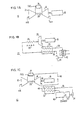
- Fig. 1A illustrates a simple gas turbine engine 10 which includes a compressor 12, a combustion chamber 14, a turbine 16, and a load 18.
- the controlling parameters are the turbine inlet temperature, TIT, the compression ratio, CPR, and the engine RPM.
- the turbine exhaust temperature is used as a measure of TIT.
- the turbine outlet temperature T exh is linked in a one-to-one corresponding fashion with the turbine inlet temperature through knowledge of the turbine characteristics.
- the controlling parameter is the fuel flow to the system which effects the turbine inlet temperature of the engine directly.
- the engine has operating limits, of course, due in part to the inertial nature of the heavy engine rotor 20. Therefore the fuel control system must have a differential loop that anticipates the engine response and programs the fuel requirement to produce the response to load variation without exceeding turbine inlet temperatures.
- the gas turbine has an inherent partial feedback loop because of the fact that the turbine-produced power drives the compressor. Therefore, only the power in excess of that required by the compressor is available to drive the load.
- Fig. 1 B depicts a steam (Rankine) cycle engine 22 operating within a Cheng-cycle dual-fluid engine including fired boiler 24, heat input 26, turbine 28, load 18, waste heat boiler or heat exchanger 32, and pump 34.
- This system is unique in that the steam expanded through the turbine 28 gives away much of its discharge heat to the oncoming water and steam in line 36 in waste heat boiler 32.
- the exhaust steam, line 38 is condensed in condensor 40 for return and reuse in the cycle or wasted in an open cycle.
- feed water is pumped through the waste heat boiler 32 to become superheated steam.
- the steam is fed into the fired boiler 24 and heated further to the designed gas turbine inlet temperature, determined by the turbine inlet temperature of the gas turbine of Fig.
- Fig. 1C is a block schematic diagram of the Cheng dual-fluid cycle engine 42 illustrating the two cycles in parallel. Where applicable the reference numerals of components of Figs. 1A and 1B are used in Fig. 1C. A detailed description of this engine cycle is set forth in US-A-4,128,994. Added to the heat engine 42 of Fig. 1C is a waste water clean-up 43 before pump 34.
- the combining or superimposition of the two cycles in a parallel arrangement simplifies the component mechanical arrangement of the powerplant.
- the engine has only one output shaft 48; additional heating of the steam by the combustion products is simple; and the steam turbine is eliminated. This represents a significant saving in costs of producing such an engine as compared to the typical "combined cycle" engine.
- the control functions become more complex.
- the Cheng cycle can be dissected superifically into two parallel cycles, the mutual interaction between the gaseous working fluid of the Brayton cycle and the liquid vapor working fluids of the Rankine cycle produces more than parallel work output.
- Air has a gamma function close to 1.4 and steam has a gamma function close to 1.28.
- the gamma function (specific heat ratio) is implicitly dependent on both temperature and pressure.
- the mixing of the working fluids makes the expansion process dependent on the mixture ratio of the working fluids as well, because the proportional relationship between turbine inlet temperature and exhaust temperature of a simple gas turbine or a simple steam turbine at a given pressure ratio and component efficiency does not hold for a Cheng-cycle system.
- both the turbine inlet temperature corresponding to best efficiency and the respective working fluid ratios have to be computed for an engine of .fixed hardware components.
- the correct operating parameters for each point representing a range of partial load operations can be calculated using the method indicated in US-A-4,128,994 except that the calculations must be made at partial load and with real (fixed) engine component characteristics.
- the highest efficiencies at reduced load occur, surprisingly, at reduced turbine inlet temperatures, which the control system produces as a result rather than as a controlled reference variable.
- a control system concept applicable to the series combined cycle (COGAS) engine is first described.
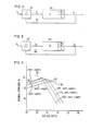
- a standard feedback control system 50 for a simple gas turbine is illustrated schematically.
- R indicates a desired setting based upon the engine load.
- R is compared with a feedback signal indicative of the actual output setting at comparator 52.
- An error signal E results which is sent to control unit 54, which provides a signal to increase or decrease the fuel flow depending on error E i .
- a new feedback signal C based upon the new actual fuel flow, is sent back to the comparator 52.
- Control unit 54 has certain boundary limits in order to avoid compressor stall.
- the control system 50 must have a built-in auxiliary control loop for engine start-up and shut-down but it is not discussed here.
- the controlling parameter in this case is the fuel flow rate, which establishes a certain air-fuel ratio to obtain the turbine inlet temperature necessary to produce the desired temperature.
- Fig. 3 the same simple control loop 50' is diagrammed for the Rankine or steam cycle system.
- the steam cycle follows the gas turbine cycle in a serial fashion.
- a preset load condition as given by R 2 , is compared with the feedback signal C 2 at comparator 52, which in this case can be the steam temperature, the turbine exhaust temperature, boiler pressure, etc. to produce an error signal E 2 .
- This signal is sent to the controller 54.
- the controller 54 either increases or decreases the steam flow rate as the control parameter instead of the fuel flow rate in the gas turbine system 50.
- the air, fuel, and steam flow rates can be adjusted to maintain the continuous rating maximum turbine inlet temperature.
- the design continuous-rating maximum turbine inlet temperature does not produce the highest efficiency at partial toads.
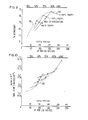
- Figs. 4, 5 and 6 are a series of plots for a specific engine to illustrate the control functions for that engine, in accordance with the present invention.
- Fig. 4 illustrates the thermal efficiencies for a given known, single-shaft turbine engine in terms of air/fuel ratio of a dual-fluid cycle engine at different load conditions.
- a number of examples of turbine inlet temperature conditions namely 760°C, 788°C and 816°C respectively (1400°F, 1450°F and 1500°F) are shown, as an independent parameter within the plot.
- the engine has a compression ratio of 7.3 to 1, inlet pressure of 0.98 bar (14.3 PSIA) exhaust pressure of 1.04 bar (15.1 PSIA), inlet temperature of 27°C (80°F) and 60% relative humidity.
- Performance is plotted against air/fuel ratio in Fig. 4 because this represents the energy input to the engine 42.
- An engine design point control path 60 links all the peak efficiency design points at different TITs with a fixed AT "top” and "neck". This graph shows clearly the unexpected result that maximum efficiencies are achieved by a lowering of the turbine inlet temperature as the partial load gets smaller.
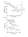
- Fig. 5 represents the power output per mass unit of air flow through the turbine of Fig. 4 for the same turbine inlet temperatures, as a function of the air-fuel ratio.
- the peak thermal efficiency for such a single-shaft, constant RPM system, for which the compressor air flow rate is nearly constant occurs at discrete air-fuel ratios.
- the locus of such points is indicated by the control path 60. If, in throttling the engine for lesser load (increased air-fuel ratio) one changes the air-fuel ratio and the steam-to-air ratio to maintain a fixed turbine inlet temperature at the lower power output of the engine, the engine efficiency falls off faster than if the turbine inlet temperature is also allowed to fall, and the steam-air and air-fuel ratios re-optimized. In other words, a constant TIT at varying load conditions is not desirable to maximize engine efficiency.
- Fig. 6 presents the data already shown in Figs. 4 and 5 as a cross plot of steam-air flow ratio, XmiX, versus air-fuel flow ratio, at varying partial loads. This plot shows that the steam-to-air flow rate along a constant TIT operating path is highly nonlinear and as a matter of fact is discontinuous around peak efficiency points.
- the optimum efficiency operating line for a Cheng dual-fluid engine thus involves changing the air-fuel ratio, steam-air ratio and turbine inlet temperature simultaneously when going from the design load condition to a lesser load condition.
- the engine design is optimized at the maximum efficiency point corresponding to a continuous-running maximum turbine inlet temperature. Assuming this to be the case, to accommodate power loads above the design load of the engine, requires departure from the (apparent) optimum efficiency operating line in order not to exceed the assumed limiting turbine inlet temperature. Thus the "best" operating line has a discontinuity (change of slope) at or near the maximum efficiency point for 100 percent load.
- the preferred engine operating lines corresponding to a variable turbine inlet temperature, are specified such that for a given load condition the correct air-fuel ratio and steam-air ratio to maintain high thermal efficiency at partial loads can be obtained.
- the engine can not follow the design point operating line at over load due to the lack of heat exchanger surface area. At less than 100% load the surface area allows the temperature differences AT “top” and AT “neck” to be reduced below that allowed in the design.
- the "real" control path is shown as 60' in Figs. 4, 5 and 6. This is explained in detail later. The control system described next is designed to achieve this result.
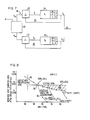
- Fig. 7 is a block schematic of a control system 80 for a Cheng dual-fluid cycle engine.
- Control system 80 uses a pre-computed multi-dimensional contoured map stored in master memory 82. This stored map contains operating conditions which link the operating parameters for high efficiency operation at each load condition for the dual-fluid cycle engine.
- the control load setting R triggers predetermined signals R, o and R 20 from memory 82 to separately establish desired operating points for a gas turbine servo system 84 and a steam servo system 86.
- the respective servo loops 84 and 86 then operate independently of each other to control, respectively, the fuel flow rate and the steam flow rate so that the engine operates at the locus of the highest peak efficiencies for that load, i.e., along the optimum control path shown in Figs. 4-6. No over-all control feedback is provided; only feedback is provided within the separate gas turbine and steam control loops.
- the components of the gas turbine control loop 84 and steam control loop 86 are basically the same as those shown in Figs. 2 and 3, respectively, for a gas turbine and steam turbine engine.
- identical numerals used in Figs. 2 and 3 are used in the following description.
- the input load setting R, o set by memory 82
- the error comparison box 52 goes to the error comparison box 52 where the actual fuel flow is compared with the desired setting R, o to produce error signal E,.
- This signal is acted upon by control unit 54 which provides a control feedback signal C, for controlling the fuel flow.
- Controlling fuel flow basically controls the engine heat input rate. Controls to compensate for barometric pressure, ambient temperature, etc., are not described here but are within the scope of skill in the art of gas turbine controls.
- the steam flow rate is controlled by the steam servo system 86.
- the input load setting R 2o set by memory 82 in response to a desired engine load condition, goes to comparator 52, producing an error signal E 2 .
- This signal is acted upon by steam controller 54, which produces a feedback control signal C 2 which establishes the correct steam flow rate.
- the steam controller senses the boiler pressure and temperature.
- the combination of the control signals C 1 and C 2 provides the right control operating signals C 3 to accommodate the actual load output such that the engine can be operated on the peak efficiency contour for the given load requirement.
- the differential, proportional, and the integrating signal processors in the respective steam and gas control loops 86 and 84 provide conventional servo-system control.
- the flow rates of air and steam may be momentarily increased or decreased beyond the ultimate steady state flow rates corresponding to the new load command.
- the flow rate overshoots are designed a priori from knowledge of the engine component dynamic characteristics so that physical or characteristic performance limits of the equipment are not exceeded.
- the fuel-air-steam ratios must be kept within the limits that would cause overheating of the turbine, and varied in a way to avoid compressor stall or surge. Fuel flow may not be dropped so suddenly with decreased load as to cause combustor flame out.
- differential processor which compares the anticipated variation with the rate of change of fuel and steam flow rate. That is, it differentiates the flow rates with respect to time.
- the differential processor controls the fuel and steam flow rate variation to initially overshoot the steady state flow requirement, then rapidly adjusts the overshoot to steady-state flow rates for the load.
- the differential response is in action only if the rate of change of flow rate is larger than a preset rate of change of flow rate.
- the threshold function can be provided by a mechanical-hydraulic system, such as a spring loaded check valve, or by an electrical system having a threshold trigger voltage with a ramp function. If the rate of change of the flow rate is smaller than the preset rate of change of flow rate, the control signal simply goes to proportional control. The proportional control must be provided with a certain gain in terms of mechanical advantages or electrical amplification.
- the fuel flow rate is set according to the master control 82 command.
- the error signals E, and E 2 are processed through integrating signal processors in both the gas and steam controllers. Any control system can be plagued with some high frqeuency short- duration noise inputs which are not true commands from the operator; mechanical vibration to the control handle transmitted through the floor, for example. Because the turbine system of a rotary machine has rotational energy stored in the rotor, the engine does not have to chase short- time duration changes. Therefore, an integrated processor is used to filter out noises as much as possible. The characteristic time of the integrated processor can be determined a priori from the known engine system component dynamics.
- the boiler 32 is an energy storage system that warrants the requirement of an integrating processor.
- Inertia of the turbine wheels is replaced by thermal lags.
- the operating contour is determined a priori.
- the memory system 82 stores precomputed values for all the operating parameters, i.e., different RPMs, pressure ratios and temperatures.
- the memory 82 produces the two signals R lo and R 20 dependent upon the particluar set of operating parameters called for, and the load condition.
- This memory control system 80 need only obtain the command of an engine operator for a different load condition to determine what operating parameters are necessary to regulate the engine for operation at the peak efficiency.
- the controlled parameters are: (1) fuel flow rate and (2) the steam flow rate.
- the memory 82 essentially eliminates the freedom of the control paths of the parallel combination of Brayton and Rankine cycle. As a result, for a given load condition away from peak load condition, the turbine inlet temperature is no longer maintained at the highest turbine inlet temperature for a given throughput. Rather, the turbine inlet temperature is computed for the load setting from a known engine operating map and stored in the memory system 82.
- the control of the engine is accomplished by reference to the memory 82 in such a way that the load setting provides commands to the fuel setting and the steam flow rate setting without an overall feedback control.
- the memory control system 80 constitutes an open-loop, positive control system rather than a feedback control system on top of two individual feedback systems.
- Figs. 4, 5 and 6 show typical steady state operating characteristics of a single-shaft dual-fluid cycle engine. These allow one to determine the limitations and characteristics of all the possible control paths, as will be explained.
- the prior Cheng patent allows one to determine peak operating regions for a particular dual-fluid cycle engine design.
- a temperature difference OT t°P and ⁇ T neck , for the heat exchanger 32 is assumed on the grounds of heat exchanger size and economic trade off.
- the required surface area for the heat exchanger varies at different turbine inlet temperatures, TIT, and compression ratios, CPR.
- the heat transfer surface areas for superheater, evaporator, and economizer for heat exchanger 32 are fixed.
- the temperature differentials ⁇ T top and ⁇ T neck are no longer design constraint considerations. Under partial load conditions excess surface area is available in the waste heat boiler. Thus, the heat transfer area is greater than that required to maintain llTtop and llTneck at less than 100 percent load. Consequently, these temperature differences decrease.
- the fixed surface area of heat exchanger 32 is inadequate, however, to maintain the design ⁇ T top and ⁇ T neck along the overload control path about 100% load.
- Fig. 8 which plots the heat exchanger 32 area per unit of air flow as a function of air-fuel ratio both for the design case 90 and an actual heat exchanger case 92.
- the "real" heat exchanger case 92 is a horizontal line passing through the design operating curve 90 at 100% load.
- the additional heat exchanger surface area available at partial loads means smaller ⁇ T top , hence higher engine overall efficiency at partial load. This is indicated by the cross-hatched area 94.
- the operating map is generated as a perturbation over that of the engine design map. This is accomplished by examining the horizontal control path 92 of "real" heat exchanger 32. As explained, improved efficiency results in the partial load region due to the available excess heat exchanger area. As also explained, during partial load conditions, the prescribed maximum temperature difference between the exhaust gas mixture and the incoming steam are removed.
- the new peak operating point is computed based upon a steam/air ratio which satisfies the two conditions, set forth in US ⁇ A ⁇ 4,128,994, simultaneously: (1) maximum heat recovery from the exhaust gases, i.e., lowest effective temperature of the exhaust gases and (2) maximum superheat steam temperature prior to entering the combustion chamber 14.
- the control memory 82 requires information on load versus steam flow and fuel flow, at given ambient temperature, relative humidity and atmospheric pressure. The peak efficiency points defining one optimum control path are therefore recalculated from the information in Figs. 4, 5 and 6. This is compiled in Figs. 9-11.
- Fig. 9 is a plot of efficiency
- Fig. 10 is a plot of fuel flow
- Fig. 11 is a plot of steam flow all as a function of output power per mass unit of air flow per second.
- the control path 60 shows the control path of maximum efficiency.
- the load output in terms of power for full and partial load is normalized to one mass unit per second air flow through the compressor, such that for a single-shaft constant-RPM engine for generating electricity the air flow rate is essentially a constant.
- Other engines having power turbines with variable RPM load follow essentially the same procedure only the normalization factor is connected by air flow, due to RPM change according to a compressor map.
- control path information As an alternative method to store control path information, one can link fuel control to steam flow rate. From Figs. 9, 10 and 11 one can cross plot the control path 60 as a ratio of steam-fuel flow ratio as a function of output power per mass unit of air flow per second as shown in Fig. 12. These relationships can be stored in memory 82 to link the fuel control with steam control.
- Efficiency of an engine system can be measured in either of two ways: one as a fraction of the available energy that is utilized as either work or heat.
- Co-generation is a total energy system which utilizes the waste heat to generate process steam. The energy of the process steam is counted as an output of the system so that the overall efficiency is increased.
- an alternative control path 96 for the engine is to reduce the steam-flow rate while reducing the load output so that the engine runs at maximum designed turbine inlet temperature.
- the excessive boiler 32 surface area is then used for co-generation, such that only the proper amount of steam is used in the Cheng cycle engine 42 at a given load.
- the co-generation path 96 represents another limit of the choice of control path.
- the control path is bounded by constant maximum TIT.
- the first limit is the control path linking all the highest possible efficiency points at constant heat exchanger surface area. This follows the horizontal path 92.
- Other paths can be chosen in the region between path 92 and 96 to satisfy specific applications but generally they are bounded by the co-generation path 96 and the optimum engine efficiency control path 92.
- Figs. 4, 5 and 6 show the complex nature of identifying the peaks for a single-shaft single- speed dual-fluid cycle engine. If the variable load can be accommodated by changing RPM then air flow and pressure ratio become dominant operating variables. Changing RPM occurs in the case for pumping a fluid, in contrast to driving a utility generator, where synchronous turbine-generator speed must be maintained. To identify the operating conditions for peak efficiencies for an engine with these additional variable parameters, two more operating maps are required. One can regard Figs. 4, 5 and 6 as representative cross sections of three-dimensional maps where the additional dimension represents either compression ratio or air flow. Such plots can be readily made using the methods similar to those defined in the prior Cheng patent but with some differences in parametric conditions for each compression ratio or air flow, and then plotted or prepared as a contoured multiple-dimensional surface map.
- the use of a dual-shaft arrangement for the Cheng cycle engine system permits the use of a variable-speed turbine to drive the compressor to supply whatever air flow is required to accommodate the load at high efficiency.
- the first turbine, or core turbine, that drives the compressor can be equipped with variable stator vanes.
- the variable stator vanes in such a case do not add another degree of freedom to the engine operation because the position of the guide vanes is determined by the required air and steam flow.
- variable air flow and compression ratio required to drive the work turbine, which in turn, may be either constant- speed or variable-speed, under its load condition, constitutes in essence a problem similar to that discussed above for the single-shaft variable-speed engine.
- the computations required to identify the maximum efficiency conditions corresponding to each load become increasingly complex.
- the best-efficiency optimum operating condition can be represented by a multiple-dimensional contoured surface in which each point represents the simultaneous variation of several of the engine operating parameters. It is evident that this control must be able to process the additional (compressor RPM or pressure ratio) input in determining how to establish the new operating parameters to accommodate the load, and it must be equipped with differential, proportional and integral control responses that operate on the additional input. From the multi- dimension control surface, a unique control path is singled out for a specific Cheng cycle engine.
- control system for a particular dual-fluid engine is highly specific to the characteristics of the components of that particular engine configuration.
- protective devices would be employed.
- RPM governors, high temperature turbine inlet temperature limiters, boiler pressure limiters, and so on, which are not shown in the controller block background, would be integrated into the control system as in other prior art systems.
- the link of the two parallel cycles is through the memory system 82.
- the memory 82 is preprogrammed electronically in a memory storage bank or by a mechanical cam and gear system or by a combination of both. For highest efficiency operation at any load the system must be programmed to guide the dual-fluid cycle to operate along the path which links the peak efficiency points. If the engine is to be used to co-generate power and heat, then a different control path which maintains highest continuous rating turbine inlet temperature and maximizes steam production at that operating condition is used. All dual-fluid cycle engine control paths will ordinarily be bounded by conditions corresponding to their objectives.
Landscapes
- Engineering & Computer Science (AREA)
- Chemical & Material Sciences (AREA)
- Combustion & Propulsion (AREA)
- Mechanical Engineering (AREA)
- General Engineering & Computer Science (AREA)
- Engine Equipment That Uses Special Cycles (AREA)
- Control Of Turbines (AREA)
Applications Claiming Priority (2)
| Application Number | Priority Date | Filing Date | Title |
|---|---|---|---|
| US59591 | 1979-07-23 | ||
| US06/059,591 US4297841A (en) | 1979-07-23 | 1979-07-23 | Control system for Cheng dual-fluid cycle engine system |
Publications (3)
| Publication Number | Publication Date |
|---|---|
| EP0034614A1 EP0034614A1 (en) | 1981-09-02 |
| EP0034614A4 EP0034614A4 (en) | 1981-11-25 |
| EP0034614B1 true EP0034614B1 (en) | 1988-05-04 |
Family
ID=22023978
Family Applications (1)
| Application Number | Title | Priority Date | Filing Date |
|---|---|---|---|
| EP80901642A Expired EP0034614B1 (en) | 1979-07-23 | 1981-02-09 | Control system for cheng dual-fluid cycle engine system |
Country Status (7)
| Country | Link |
|---|---|
| US (1) | US4297841A (enExample) |
| EP (1) | EP0034614B1 (enExample) |
| JP (1) | JPS56500899A (enExample) |
| CA (1) | CA1159658A (enExample) |
| DE (1) | DE3072089D1 (enExample) |
| MX (1) | MX150918A (enExample) |
| WO (1) | WO1981000280A1 (enExample) |
Families Citing this family (56)
| Publication number | Priority date | Publication date | Assignee | Title |
|---|---|---|---|---|
| US4393649A (en) * | 1979-07-23 | 1983-07-19 | International Power Technology, Inc. | Steam output control system |
| US4680927A (en) * | 1979-07-23 | 1987-07-21 | International Power Technology, Inc. | Control system for Cheng dual-fluid cycle engine system |
| US4549397A (en) * | 1979-07-23 | 1985-10-29 | International Power Technology, Inc. | Control system for Cheng dual-fluid cycle engine system |
| DE3331153A1 (de) * | 1983-08-30 | 1985-03-14 | Brown, Boveri & Cie Ag, 6800 Mannheim | Gasturbinenanlage fuer offenen prozess |
| US4823546A (en) * | 1984-02-07 | 1989-04-25 | International Power Technology | Steam-injected free-turbine-type gas turbine |
| US4660376A (en) * | 1984-04-27 | 1987-04-28 | General Electric Company | Method for operating a fluid injection gas turbine engine |
| US4569195A (en) * | 1984-04-27 | 1986-02-11 | General Electric Company | Fluid injection gas turbine engine and method for operating |
| US4631914A (en) * | 1985-02-25 | 1986-12-30 | General Electric Company | Gas turbine engine of improved thermal efficiency |
| US4753068A (en) * | 1987-01-15 | 1988-06-28 | El Masri Maher A | Gas turbine cycle incorporating simultaneous, parallel, dual-mode heat recovery |
| US5170622A (en) * | 1991-04-02 | 1992-12-15 | Cheng Dah Y | Advanced regenerative parallel compound dual fluid heat engine Advanced Cheng Cycle (ACC) |
| US5233826A (en) * | 1991-04-02 | 1993-08-10 | Cheng Dah Y | Method for starting and operating an advanced regenerative parallel compound dual fluid heat engine-advanced cheng cycle (ACC) |
| US5255505A (en) * | 1992-02-21 | 1993-10-26 | Westinghouse Electric Corp. | System for capturing heat transferred from compressed cooling air in a gas turbine |
| USRE43252E1 (en) | 1992-10-27 | 2012-03-20 | Vast Power Portfolio, Llc | High efficiency low pollution hybrid Brayton cycle combustor |
| US5329758A (en) * | 1993-05-21 | 1994-07-19 | The United States Of America As Represented By The Secretary Of The Navy | Steam-augmented gas turbine |
| US5431016A (en) * | 1993-08-16 | 1995-07-11 | Loral Vought Systems Corp. | High efficiency power generation |
| US6170264B1 (en) | 1997-09-22 | 2001-01-09 | Clean Energy Systems, Inc. | Hydrocarbon combustion power generation system with CO2 sequestration |
| DE19902437C5 (de) * | 1999-01-22 | 2017-01-12 | General Electric Technology Gmbh | Verfahren und Vorrichtung zum schnellen Anfahren und zur schnellen Leistungssteigerung einer Gasturbinenanlage |
| US6247316B1 (en) | 2000-03-22 | 2001-06-19 | Clean Energy Systems, Inc. | Clean air engines for transportation and other power applications |
| US6637183B2 (en) | 2000-05-12 | 2003-10-28 | Clean Energy Systems, Inc. | Semi-closed brayton cycle gas turbine power systems |
| US7273981B2 (en) * | 2001-02-09 | 2007-09-25 | Bsst, Llc. | Thermoelectric power generation systems |
| US6539725B2 (en) * | 2001-02-09 | 2003-04-01 | Bsst Llc | Efficiency thermoelectrics utilizing thermal isolation |
| US6959555B2 (en) * | 2001-02-09 | 2005-11-01 | Bsst Llc | High power density thermoelectric systems |
| US6672076B2 (en) | 2001-02-09 | 2004-01-06 | Bsst Llc | Efficiency thermoelectrics utilizing convective heat flow |
| US7946120B2 (en) | 2001-02-09 | 2011-05-24 | Bsst, Llc | High capacity thermoelectric temperature control system |
| US7942010B2 (en) | 2001-02-09 | 2011-05-17 | Bsst, Llc | Thermoelectric power generating systems utilizing segmented thermoelectric elements |
| US7231772B2 (en) | 2001-02-09 | 2007-06-19 | Bsst Llc. | Compact, high-efficiency thermoelectric systems |
| US6868677B2 (en) | 2001-05-24 | 2005-03-22 | Clean Energy Systems, Inc. | Combined fuel cell and fuel combustion power generation systems |
| US7426835B2 (en) | 2001-08-07 | 2008-09-23 | Bsst, Llc | Thermoelectric personal environment appliance |
| US8490412B2 (en) | 2001-08-07 | 2013-07-23 | Bsst, Llc | Thermoelectric personal environment appliance |
| US6812395B2 (en) | 2001-10-24 | 2004-11-02 | Bsst Llc | Thermoelectric heterostructure assemblies element |
| US20110209740A1 (en) * | 2002-08-23 | 2011-09-01 | Bsst, Llc | High capacity thermoelectric temperature control systems |
| EP1576266B1 (en) | 2002-11-15 | 2014-09-03 | Clean Energy Systems, Inc. | Low pollution power generation system with ion transfer membrane air separation |
| WO2004081479A2 (en) | 2003-03-10 | 2004-09-23 | Clean Energy Systems, Inc. | Reheat heat exchanger power generation systems |
| WO2005100754A2 (en) | 2004-04-16 | 2005-10-27 | Clean Energy Systems, Inc. | Zero emissions closed rankine cycle power system |
| US7847179B2 (en) | 2005-06-06 | 2010-12-07 | Board Of Trustees Of Michigan State University | Thermoelectric compositions and process |
| CN101313420B (zh) | 2005-06-28 | 2011-08-17 | Bsst有限责任公司 | 具有中间回路的热电发电器 |
| US7870745B2 (en) | 2006-03-16 | 2011-01-18 | Bsst Llc | Thermoelectric device efficiency enhancement using dynamic feedback |
| US7952015B2 (en) | 2006-03-30 | 2011-05-31 | Board Of Trustees Of Michigan State University | Pb-Te-compounds doped with tin-antimony-tellurides for thermoelectric generators or peltier arrangements |
| US20080216510A1 (en) * | 2006-08-22 | 2008-09-11 | David Vandor | Combined Cycle System For Gas Turbines and Reciprocating Engines and a Method for the Use of Air as Working Fluid in Combined Cycle Power Plants |
| US20080289677A1 (en) * | 2007-05-25 | 2008-11-27 | Bsst Llc | Composite thermoelectric materials and method of manufacture |
| CN104990301B (zh) | 2007-05-25 | 2019-04-16 | 詹思姆公司 | 分配式热电加热和冷却的系统和方法 |
| ES2457819T3 (es) * | 2007-12-10 | 2014-04-29 | Alstom Technology Ltd | Procedimiento para la regulación de una turbina de gas en una central eléctrica |
| EP2244971A2 (en) * | 2008-01-14 | 2010-11-03 | The Ohio State University Research Foundation | Thermoelectric figure of merit enhancement by modification of the electronic density of states |
| EP2269240A2 (en) * | 2008-04-24 | 2011-01-05 | ZT Plus | Improved thermoelectric materials combining increased power factor and reduced thermal conductivity |
| CN102105757A (zh) | 2008-06-03 | 2011-06-22 | Bsst有限责任公司 | 热电热泵 |
| EP2349753B1 (en) | 2008-10-23 | 2016-11-23 | Gentherm Incorporated | Multi-mode hvac system with thermoelectric device |
| CN102803132A (zh) * | 2009-04-13 | 2012-11-28 | 美国俄亥俄州立大学 | 具有增强的热电功率因子的热电合金 |
| US8702013B2 (en) * | 2010-02-18 | 2014-04-22 | Igor Zhadanovsky | Vapor vacuum heating systems and integration with condensing vacuum boilers |
| WO2012135734A2 (en) | 2011-04-01 | 2012-10-04 | Zt Plus | Thermoelectric materials having porosity |
| US9293680B2 (en) | 2011-06-06 | 2016-03-22 | Gentherm Incorporated | Cartridge-based thermoelectric systems |
| US9006557B2 (en) | 2011-06-06 | 2015-04-14 | Gentherm Incorporated | Systems and methods for reducing current and increasing voltage in thermoelectric systems |
| WO2014022428A2 (en) | 2012-08-01 | 2014-02-06 | Gentherm Incorporated | High efficiency thermoelectric generation |
| US8567177B1 (en) | 2012-11-30 | 2013-10-29 | Yoganeck, LLC | Gas turbine engine system with water recycling feature |
| JP6637765B2 (ja) | 2013-01-30 | 2020-01-29 | ジェンサーム インコーポレイテッドGentherm Incorporated | 熱電ベースの熱管理システム |
| US11075331B2 (en) | 2018-07-30 | 2021-07-27 | Gentherm Incorporated | Thermoelectric device having circuitry with structural rigidity |
| US11152557B2 (en) | 2019-02-20 | 2021-10-19 | Gentherm Incorporated | Thermoelectric module with integrated printed circuit board |
Family Cites Families (13)
| Publication number | Priority date | Publication date | Assignee | Title |
|---|---|---|---|---|
| US1094060A (en) * | 1913-03-05 | 1914-04-21 | Ralph Gerber | Unloading apparatus. |
| US2327135A (en) * | 1941-11-04 | 1943-08-17 | Rumsey W Scott | Freight transfer mechanism |
| US2469678A (en) * | 1943-12-18 | 1949-05-10 | Edwin T Wyman | Combination steam and gas turbine |
| US3630397A (en) * | 1969-09-02 | 1971-12-28 | Nelson Equipment Co | Side shifting storage and transfer apparatus |
| US3657879A (en) * | 1970-01-26 | 1972-04-25 | Walter J Ewbank | Gas-steam engine |
| US3693347A (en) * | 1971-05-12 | 1972-09-26 | Gen Electric | Steam injection in gas turbines having fixed geometry components |
| US4065006A (en) * | 1973-12-27 | 1977-12-27 | Barry Leonard D | Container side-transfer system |
| US4130208A (en) * | 1974-12-02 | 1978-12-19 | Barry Leonard D | Side rails container transfer system |
| US3978661A (en) * | 1974-12-19 | 1976-09-07 | International Power Technology | Parallel-compound dual-fluid heat engine |
| US3991889A (en) * | 1975-04-15 | 1976-11-16 | Cox Robert E | Railway transportating system and apparatus therefor |
| US4124129A (en) * | 1976-01-20 | 1978-11-07 | Barry Leonard D | Loader and storage system |
| CA1083835A (en) * | 1976-07-14 | 1980-08-19 | International Power Technology, Inc. | Regenerative parallel compound dual-fluid heat engine |
| US4248039A (en) * | 1978-12-06 | 1981-02-03 | International Power Technology, Inc. | Regenerative parallel compound dual fluid heat engine |
-
1979
- 1979-07-23 US US06/059,591 patent/US4297841A/en not_active Expired - Lifetime
-
1980
- 1980-07-07 JP JP50198280A patent/JPS56500899A/ja active Pending
- 1980-07-07 DE DE8080901642T patent/DE3072089D1/de not_active Expired
- 1980-07-07 WO PCT/US1980/000859 patent/WO1981000280A1/en not_active Ceased
- 1980-07-22 MX MX183252A patent/MX150918A/es unknown
- 1980-07-23 CA CA000356838A patent/CA1159658A/en not_active Expired
-
1981
- 1981-02-09 EP EP80901642A patent/EP0034614B1/en not_active Expired
Also Published As
| Publication number | Publication date |
|---|---|
| EP0034614A4 (en) | 1981-11-25 |
| WO1981000280A1 (en) | 1981-02-05 |
| DE3072089D1 (en) | 1988-06-09 |
| JPS56500899A (enExample) | 1981-07-02 |
| CA1159658A (en) | 1984-01-03 |
| MX150918A (es) | 1984-08-16 |
| EP0034614A1 (en) | 1981-09-02 |
| US4297841A (en) | 1981-11-03 |
Similar Documents
| Publication | Publication Date | Title |
|---|---|---|
| EP0034614B1 (en) | Control system for cheng dual-fluid cycle engine system | |
| US4680927A (en) | Control system for Cheng dual-fluid cycle engine system | |
| US4499721A (en) | Control system for Cheng dual-fluid cycle engine system | |
| US5203159A (en) | Pressurized fluidized bed combustion combined cycle power plant and method of operating the same | |
| US5042246A (en) | Control system for single shaft combined cycle gas and steam turbine unit | |
| CS199691A3 (en) | Process and system for detecting and controlling of a combined turbine unit excessive speed | |
| US4549397A (en) | Control system for Cheng dual-fluid cycle engine system | |
| US2219994A (en) | Gas turbine plant and regulating system therefor | |
| EP1063402B1 (en) | Method for operating an industrial gas turbine with optimal performance | |
| US3422800A (en) | Combined gas turbine and waste heat boiler control system | |
| US4450363A (en) | Coordinated control technique and arrangement for steam power generating system | |
| EP0172224B2 (en) | Steam-injected free-turbine-type gas turbine | |
| US3505811A (en) | Control system for a combined gas turbine and steam turbine power plant | |
| JPS6118649B2 (enExample) | ||
| JPH01285608A (ja) | コンバインドプラントの運転方法及び装置 | |
| US4823546A (en) | Steam-injected free-turbine-type gas turbine | |
| US4854121A (en) | Combined cycle power plant capable of controlling water level in boiler drum of power plant | |
| US4393649A (en) | Steam output control system | |
| CN100385092C (zh) | 用于蒸汽轮机的快速发电系统及方法 | |
| US4417438A (en) | Control system for Cheng dual-fluid cycle engine system | |
| EP0353374B1 (en) | Gas turbine unit for combined production of electricity and heat and method for operating such unit | |
| CA1177263A (en) | Control system for dual-fluid brayton/rankine cycle engine system | |
| JPH0811922B2 (ja) | 部分周蒸気タービンの熱消費率改善方法 | |
| GB2176248A (en) | Turbine control | |
| US4175382A (en) | Steam power plant with pressure-fired boiler |
Legal Events
| Date | Code | Title | Description |
|---|---|---|---|
| PUAI | Public reference made under article 153(3) epc to a published international application that has entered the european phase |
Free format text: ORIGINAL CODE: 0009012 |
|
| 17P | Request for examination filed |
Effective date: 19810316 |
|
| AK | Designated contracting states |
Designated state(s): CH DE FR GB NL SE |
|
| GRAA | (expected) grant |
Free format text: ORIGINAL CODE: 0009210 |
|
| AK | Designated contracting states |
Kind code of ref document: B1 Designated state(s): CH DE FR GB LI NL SE |
|
| REF | Corresponds to: |
Ref document number: 3072089 Country of ref document: DE Date of ref document: 19880609 |
|
| ET | Fr: translation filed | ||
| PLBE | No opposition filed within time limit |
Free format text: ORIGINAL CODE: 0009261 |
|
| STAA | Information on the status of an ep patent application or granted ep patent |
Free format text: STATUS: NO OPPOSITION FILED WITHIN TIME LIMIT |
|
| 26N | No opposition filed | ||
| REG | Reference to a national code |
Ref country code: CH Ref legal event code: PUE Owner name: SGP-VA ENERGIE- UND UMWELTTECHNIK GESELLSCHAFT M.B Ref country code: CH Ref legal event code: PFA Free format text: INTERNATIONAL POWER TECHNOLOGY, INC. |
|
| NLS | Nl: assignments of ep-patents |
Owner name: SGP-VA ENERGIE- UND UMWELTTECHNIK GESELLSCHAFT M.B |
|
| REG | Reference to a national code |
Ref country code: FR Ref legal event code: TP |
|
| REG | Reference to a national code |
Ref country code: GB Ref legal event code: 732 |
|
| EAL | Se: european patent in force in sweden |
Ref document number: 80901642.1 |
|
| PGFP | Annual fee paid to national office [announced via postgrant information from national office to epo] |
Ref country code: GB Payment date: 19990624 Year of fee payment: 20 |
|
| PGFP | Annual fee paid to national office [announced via postgrant information from national office to epo] |
Ref country code: SE Payment date: 19990628 Year of fee payment: 20 Ref country code: FR Payment date: 19990628 Year of fee payment: 20 Ref country code: DE Payment date: 19990628 Year of fee payment: 20 Ref country code: CH Payment date: 19990628 Year of fee payment: 20 |
|
| PGFP | Annual fee paid to national office [announced via postgrant information from national office to epo] |
Ref country code: NL Payment date: 19990630 Year of fee payment: 20 |
|
| PG25 | Lapsed in a contracting state [announced via postgrant information from national office to epo] |
Ref country code: LI Free format text: LAPSE BECAUSE OF EXPIRATION OF PROTECTION Effective date: 20000706 Ref country code: GB Free format text: LAPSE BECAUSE OF EXPIRATION OF PROTECTION Effective date: 20000706 Ref country code: CH Free format text: LAPSE BECAUSE OF EXPIRATION OF PROTECTION Effective date: 20000706 |
|
| PG25 | Lapsed in a contracting state [announced via postgrant information from national office to epo] |
Ref country code: NL Free format text: LAPSE BECAUSE OF EXPIRATION OF PROTECTION Effective date: 20000707 |
|
| REG | Reference to a national code |
Ref country code: GB Ref legal event code: PE20 Effective date: 20000706 |
|
| PG25 | Lapsed in a contracting state [announced via postgrant information from national office to epo] |
Ref country code: SE Free format text: THE PATENT HAS BEEN ANNULLED BY A DECISION OF A NATIONAL AUTHORITY Effective date: 20000730 |
|
| REG | Reference to a national code |
Ref country code: CH Ref legal event code: PL |
|
| NLV7 | Nl: ceased due to reaching the maximum lifetime of a patent |
Effective date: 20000707 |
|
| EUG | Se: european patent has lapsed |
Ref document number: 80901642.1 |