EP0034591B1 - Apparatus for controlling capacity of a multiple-stage cooling system - Google Patents
Apparatus for controlling capacity of a multiple-stage cooling system Download PDFInfo
- Publication number
- EP0034591B1 EP0034591B1 EP80901475A EP80901475A EP0034591B1 EP 0034591 B1 EP0034591 B1 EP 0034591B1 EP 80901475 A EP80901475 A EP 80901475A EP 80901475 A EP80901475 A EP 80901475A EP 0034591 B1 EP0034591 B1 EP 0034591B1
- Authority
- EP
- European Patent Office
- Prior art keywords
- cut
- pressure
- signals
- delayed
- capacity
- Prior art date
- Legal status (The legal status is an assumption and is not a legal conclusion. Google has not performed a legal analysis and makes no representation as to the accuracy of the status listed.)
- Expired
Links
- 238000001816 cooling Methods 0.000 title claims abstract description 46
- 238000012544 monitoring process Methods 0.000 claims description 8
- 230000007423 decrease Effects 0.000 claims description 7
- 238000005259 measurement Methods 0.000 claims description 5
- 238000001514 detection method Methods 0.000 claims description 3
- 230000000737 periodic effect Effects 0.000 claims 1
- 239000003507 refrigerant Substances 0.000 abstract description 10
- 239000012530 fluid Substances 0.000 abstract description 6
- 238000000034 method Methods 0.000 abstract description 3
- 239000004020 conductor Substances 0.000 description 35
- 230000003111 delayed effect Effects 0.000 description 13
- 238000005057 refrigeration Methods 0.000 description 13
- 239000007788 liquid Substances 0.000 description 4
- XLYOFNOQVPJJNP-UHFFFAOYSA-N water Substances O XLYOFNOQVPJJNP-UHFFFAOYSA-N 0.000 description 3
- 230000003213 activating effect Effects 0.000 description 2
- 230000001351 cycling effect Effects 0.000 description 2
- 230000001419 dependent effect Effects 0.000 description 2
- 238000013461 design Methods 0.000 description 2
- 238000010438 heat treatment Methods 0.000 description 2
- 238000012986 modification Methods 0.000 description 2
- 230000004048 modification Effects 0.000 description 2
- 238000004378 air conditioning Methods 0.000 description 1
- 230000015572 biosynthetic process Effects 0.000 description 1
- 230000006835 compression Effects 0.000 description 1
- 238000007906 compression Methods 0.000 description 1
- 230000001934 delay Effects 0.000 description 1
- 238000010586 diagram Methods 0.000 description 1
- 238000007599 discharging Methods 0.000 description 1
- 230000007774 longterm Effects 0.000 description 1
- 238000012423 maintenance Methods 0.000 description 1
- 230000007257 malfunction Effects 0.000 description 1
- 230000001737 promoting effect Effects 0.000 description 1
- 230000003252 repetitive effect Effects 0.000 description 1
Images
Classifications
-
- F—MECHANICAL ENGINEERING; LIGHTING; HEATING; WEAPONS; BLASTING
- F25—REFRIGERATION OR COOLING; COMBINED HEATING AND REFRIGERATION SYSTEMS; HEAT PUMP SYSTEMS; MANUFACTURE OR STORAGE OF ICE; LIQUEFACTION SOLIDIFICATION OF GASES
- F25B—REFRIGERATION MACHINES, PLANTS OR SYSTEMS; COMBINED HEATING AND REFRIGERATION SYSTEMS; HEAT PUMP SYSTEMS
- F25B49/00—Arrangement or mounting of control or safety devices
- F25B49/02—Arrangement or mounting of control or safety devices for compression type machines, plants or systems
- F25B49/027—Condenser control arrangements
-
- F—MECHANICAL ENGINEERING; LIGHTING; HEATING; WEAPONS; BLASTING
- F25—REFRIGERATION OR COOLING; COMBINED HEATING AND REFRIGERATION SYSTEMS; HEAT PUMP SYSTEMS; MANUFACTURE OR STORAGE OF ICE; LIQUEFACTION SOLIDIFICATION OF GASES
- F25B—REFRIGERATION MACHINES, PLANTS OR SYSTEMS; COMBINED HEATING AND REFRIGERATION SYSTEMS; HEAT PUMP SYSTEMS
- F25B49/00—Arrangement or mounting of control or safety devices
- F25B49/02—Arrangement or mounting of control or safety devices for compression type machines, plants or systems
- F25B49/022—Compressor control arrangements
-
- G—PHYSICS
- G05—CONTROLLING; REGULATING
- G05D—SYSTEMS FOR CONTROLLING OR REGULATING NON-ELECTRIC VARIABLES
- G05D23/00—Control of temperature
- G05D23/19—Control of temperature characterised by the use of electric means
- G05D23/1906—Control of temperature characterised by the use of electric means using an analogue comparing device
- G05D23/1912—Control of temperature characterised by the use of electric means using an analogue comparing device whose output amplitude can take more than two discrete values
-
- G—PHYSICS
- G05—CONTROLLING; REGULATING
- G05D—SYSTEMS FOR CONTROLLING OR REGULATING NON-ELECTRIC VARIABLES
- G05D23/00—Control of temperature
- G05D23/19—Control of temperature characterised by the use of electric means
- G05D23/20—Control of temperature characterised by the use of electric means with sensing elements having variation of electric or magnetic properties with change of temperature
-
- F—MECHANICAL ENGINEERING; LIGHTING; HEATING; WEAPONS; BLASTING
- F25—REFRIGERATION OR COOLING; COMBINED HEATING AND REFRIGERATION SYSTEMS; HEAT PUMP SYSTEMS; MANUFACTURE OR STORAGE OF ICE; LIQUEFACTION SOLIDIFICATION OF GASES
- F25B—REFRIGERATION MACHINES, PLANTS OR SYSTEMS; COMBINED HEATING AND REFRIGERATION SYSTEMS; HEAT PUMP SYSTEMS
- F25B2400/00—General features or devices for refrigeration machines, plants or systems, combined heating and refrigeration systems or heat-pump systems, i.e. not limited to a particular subgroup of F25B
- F25B2400/07—Details of compressors or related parts
- F25B2400/075—Details of compressors or related parts with parallel compressors
-
- F—MECHANICAL ENGINEERING; LIGHTING; HEATING; WEAPONS; BLASTING
- F25—REFRIGERATION OR COOLING; COMBINED HEATING AND REFRIGERATION SYSTEMS; HEAT PUMP SYSTEMS; MANUFACTURE OR STORAGE OF ICE; LIQUEFACTION SOLIDIFICATION OF GASES
- F25B—REFRIGERATION MACHINES, PLANTS OR SYSTEMS; COMBINED HEATING AND REFRIGERATION SYSTEMS; HEAT PUMP SYSTEMS
- F25B2400/00—General features or devices for refrigeration machines, plants or systems, combined heating and refrigeration systems or heat-pump systems, i.e. not limited to a particular subgroup of F25B
- F25B2400/23—Separators
-
- F—MECHANICAL ENGINEERING; LIGHTING; HEATING; WEAPONS; BLASTING
- F25—REFRIGERATION OR COOLING; COMBINED HEATING AND REFRIGERATION SYSTEMS; HEAT PUMP SYSTEMS; MANUFACTURE OR STORAGE OF ICE; LIQUEFACTION SOLIDIFICATION OF GASES
- F25B—REFRIGERATION MACHINES, PLANTS OR SYSTEMS; COMBINED HEATING AND REFRIGERATION SYSTEMS; HEAT PUMP SYSTEMS
- F25B2600/00—Control issues
- F25B2600/02—Compressor control
- F25B2600/025—Compressor control by controlling speed
- F25B2600/0253—Compressor control by controlling speed with variable speed
-
- Y—GENERAL TAGGING OF NEW TECHNOLOGICAL DEVELOPMENTS; GENERAL TAGGING OF CROSS-SECTIONAL TECHNOLOGIES SPANNING OVER SEVERAL SECTIONS OF THE IPC; TECHNICAL SUBJECTS COVERED BY FORMER USPC CROSS-REFERENCE ART COLLECTIONS [XRACs] AND DIGESTS
- Y02—TECHNOLOGIES OR APPLICATIONS FOR MITIGATION OR ADAPTATION AGAINST CLIMATE CHANGE
- Y02B—CLIMATE CHANGE MITIGATION TECHNOLOGIES RELATED TO BUILDINGS, e.g. HOUSING, HOUSE APPLIANCES OR RELATED END-USER APPLICATIONS
- Y02B30/00—Energy efficient heating, ventilation or air conditioning [HVAC]
- Y02B30/70—Efficient control or regulation technologies, e.g. for control of refrigerant flow, motor or heating
Definitions
- This invention relates to an apparatus for increasing the performance of a multi-stage refrigeration or cooling system both in terms of matching load to demand as closely as possible in terms of economic use of all of the compressors.
- Patents which are typical of the prior art for mechanically or electromechanically controlling refrigeration compressor capacity include the following U.S. Patent Nos: 3,885,938; 3,828,152; 3,719,057; 3,581,519, 3,580,006; 3,552,137; 3,377,816 and 3,792,317.
- time delay means responsive to said measurement means for producing a time delay prior to generating a corresponding cut-in or cut-out signal
- selection means for selecting at least one compressor to be energised or deenergised in response to a cut-in or cut-out signal so as to match system capacity to the cooling load.
- the selection means includes circuit means for tandemly energising a combination of said compressors from a number of possible combinations that exceeds the number of preselected compressors in the system.
- the U.S. Patent 3717300 (Evaids). This describes a temperature control apparatus for heating hot water by means of electrical resistance elements which are protected in a closed loop and are energised and deenergised by means of a Wheatstone bridge balancing circuit containing a thermistor.
- the circuit is an integrated electronic circuit which relies upon closely matched resistors, a number of which are temperature dependent. It is inherently subject to malfunction through failure of a component and would be difficult to adapt to purposes other than its intended purpose.
- the circuit operates on a FIFO strategy (first-in, first-out).
- the present invention is based upon the realisation of the important advantages to be obtained by utilisation of the strategy defined in the first characteristic feature, e.g. a FIFO strategy, in a cooling system based upon tendemly connected compressors in a common cooling duct and that these advantages can be simply and reliably brought about through an improved control means based upon logic circuits which can ensure safe long term use and ease of maintenance, and which enable the cooling system to operate at close pressure settings giving higher performance and energy saving.
- the strategy defined in the first characteristic feature e.g. a FIFO strategy
- control circuit means comprises,
- the status monitoring means comprises a counter for receiving said delayed-increase and delayed-decrease capacity signals from said time delay means and generating in response thereto one of two corresponding successively repeatable series of cut-in and cut-out control signal outputs, the number of control signal outputs in each series at least equalling the number of cooling stages in the system
- said enabling means comprises a latch circuit for receiving each of said cut-in control signal outputs as "set” signals generating in response thereto a selected one of a single successively repeatable series of cooling stage "on” signals for cutting-in a corresponding cooling stage, said latch circuit further receiving each of said cut-out control signal outputs as "reset” signals removing in response thereto a selected one of said "on” signals from said latch circuit series for cutting-out a corresponding cooling stage, said actuating means being responsive to said "on” signals, and means being provided if necessary for disabling the counter when all of the compressors are on or off.
- the refrigeration system capacity controller circuit 10 is shown disposed in a multiple-stage refrigeration or cooling system 20 consisting of a plurality of parallel staged refrigerant compressors 12, 14, 16, and 18 for discharging compressed pressurized refrigerant vapor through discharge line 22 to a condenser coil 25 where the pressurized refrigerant vapor is condensed to a liquid and then delivered to a receiver vessel 26.
- the liquid refrigerant flows through line 28 and through an expansion device or valve 30, typically a mechanical expansion valve responding to the temperature in suction line 38 as sensed by temperature sensing device 32.
- the temperature signal from sensor 32 is applied to valve 30 through conductor 33 to initiate the expansion valve action.
- the liquid refrigerant is injected through expansion device 30 into the evaporator coil 35 where the liquid refrigerant, encountering the low pressure of the evaporator coil, boils and evaporates thus absorbing heat from the evaporator coil.
- the hot vaporized refrigerant from the evaporator coil is drawn through suction line 38 to the inlet ports of the multiple compressors 12-18.
- the number of parallel compressors to be staged in the system varies according to the refrigerating or cooling system load. In Figure 1, three compressors are shown in dotted lines as 12, 14 and 16 and an "N"th number of compressors is shown by compressor 18.
- a pressure transducer 40 is attached to the suction line 38 and determines the refrigerant vapor pressure within suction line 38 and generates an electrical signal representative of the measured pressure.
- the signal is applied through conductor 42 as an input to the capacity controller circuit 10, which will be hereinafter described in greater detail.
- the output of the controller circuit 10 is a plurality of outputs corresponding to the number of the plurality of cooling stages or parallel compressors staged in the system. Accordingly, there are a corresponding "N" number of outputs from the capacity controller circuit 10 labelled 1, 2, 3 and N.
- the controller circuit output 1 is applied through conductor 56 to the coil of a relay 44 which controls relay switch contacts 45 for applying AC power via conductors 52 and 54 to the first compressor 12 for energizing the compressor when it is desired to cut the compressor into the system.
- the 2, 3 and N outputs of the capacity controller circuit are applied through conductors 58, 60 and 62, respectively, to the coils of relays 46, 48 and 50, respectively, for successively closing switches 47, 49 and 51, respectively, for successively applying AC electrical power to the 2, 3, and N compressors, respectively, for either turning on or turning off the compressors in a staged sequence.
- the pressure detecting means or transducer 40 is shown sealingly inserted into the refrigerant vapor flow 65 in suction line tubing 38.
- Pressure transducer 40 may be any conventional pressure detecting means for generating an electrical signal representative of the pressure within line 38.
- the pressure signal from transducer 40 is applied through conductors 42 and 70 to the positive input of a comparator circuit 74, and through conductors 42 and 72 to the negative input of a second comparator circuit 76.
- a voltage potential is applied through a voltage varying means such as a potentiometer 75 to the negative input of the comparator circuit 74.
- a voltage is applied through a voltage varying means such as potentiometer 77 to the positive input of the comparator circuit 76 to set a predetermined "cut-out” pressure for the system.
- Comparator circuit 74 compares the predetermined cooling system "cut-in” pressure (set by potentiometer 75) against the suction line pressure continuously detected by pressure transducer 40 and produces a "cut-in” electrical signal when the measured pressure exceeds the predetermined "cut-in” pressure.
- Comparator circuit 76 compares the predetermined cooling system "cut-out” pressure (set by potentiometer 77) against the pressure continuously detected by the pressure transducer 40 and produces a "cut-out” electrical signal when the detected system pressure exceeds the predetermined "cut-out” pressure.
- transducer 40 potentiometers 75 and 77 for establishing system pressure "cut-in” or “cut-out” pressure levels and the comparators 74 and 76 constitute detection means 64 for establishing a selected cooling stage “cut-in” or “cut-out” pressure and determining when those established pressures have been reached and providing an output signal in response thereto, i.e., output of comparators 74 or 76.
- the "cut-in" signal of comparator 74 is applied through conductor 78 to a timer 82 which generates an output electrical control signal after a first predetermined minimum time delay.
- the delayed time output control signal is applied through conductor 86 as an input to a counter 90.
- Counter 90 is a conventional counter circuit that generates a successive plurality of outputs 1 to N corresponding to the number of staged parallel compressors in the system. Each delayed control signal received from timer 82 by counter 90 will cause a counter output signal to appear at one of the series of successive counter outputs 1, 2, 3 or N in repetitive succession, and are applied via a conductor 95 as a "set" input to a latch circuit 94.
- the latch circuit 94 is of conventional solid- state design and generates a series of repeatable successive "cut-in” electrical control signals at outputs 1, 2, 3 and N, to be applied through conductors 56, 58, 60 and 62, respectively, to a series of repeatable successive compressor control relays 44, 46, 48 and 50, respectively, in response to successive "set" input signals received via conductors 95 from the 1, 2, 3 or N outputs of counter 90. For example, if the counter 90 has an output signal at output 1 applied through a conductor 95 as a "set” input to latch circuit 94, latch circuit 94 will generate a control signal output voltage at its 1 output (conductor 56).
- output signals from counter 90 appearing in a series successively at 2, 3 and N are applied through conductors 94 as repeatable successive "set” inputs to latch circuit 94, thereby generating "cut-in” or turn on control signals appearing at outputs 2, 3 and N (conductors 58, 60 and 62, respectively).
- the electrical control signals are voltages applied through conductors 56, 58, 60 and 62, respectively to relays 44, 46, 48 and 50, respectively, as hereinabove described for successively energizing the relays 44, 46, 48 and 50, respectively, and successively energizing or turning on one of the multiple compressors 12, 14, 16 and 18, respectively.
- the "cut-out" output signal of comparator 76 is applied through conductor 80 to a timer 84.
- Timer circuit 84 generates a delayed "cut-out” electrical control signal after a predetermined time delay.
- the control signal is applied through conductor 88 as an input to another counter circuit 92.
- Counter 92 may be identical to the counter 90 hereinabove described.
- Each successive delayed "cut-out” control signal received from timer circuit 84 generates one of a series of repeatable successive electrical signals at counter 92 outputs 1, 2, 3 and N, which are applied through conductors 93 as "reset” inputs to latch circuit 94. Receipt of the successive series of delayed "cut-out” control signals from counter 92 causes the latch circuit 94 to be reset in the succession in which the counter signals are received.
- the latch circuit outputs 1, 2, 3 and N are also connected by conductors 99 as inputs to a conventional AND gate 96.
- the AND gate 96 When all of the latch circuit outputs 1, 2, 3 and N have positive output voltages appearing thereon, the AND gate 96 generates an output signal applied through conductor 97 to counter 90 to disable counter 90 at its last count and prevent further delayed "cut-in" electrical signals received from timer 82 from generating further counter 90 output electrical signals for application to the latch circuit 94.
- the latch circuit outputs 1, 2, 3, and N are also connected by means of conductors 101 as inputs to a conventional NOR gate 98.
- NOR gate 98 will generate an electrical output signal to be applied through conductor 103 to disable counter 92 when all of the latch circuit outputs 1, 2, 3 and N have been reset and there are no output voltage signals present thereon.
- the electrical signal received from NOR gate 98 disables counter 92 and prevents any further "cut-out" delayed signals received from timer 84 from triggering any further counter 92 output signals to be applied as reset inputs to latch circuit 94.
- the operation of the capacity controlling circuit 10 can now further be described with reference to Figures 1, 2 and 4.
- the graph of Figure 4 depicts the system refrigerating fluid vs. time and is represented by pressure trace 121.
- the selected "cut-in" pressure represented by line 120 is set for the system by potentiometer 75 as one input to the comparator 74, as hereinabove described.
- the selected "cut-out" pressure represented by line 130 is set by potentiometer 77 as one input to comparator 76, as hereinabove described.
- the desired system suction line pressure range ⁇ P has been selected for optimum efficiency of the system.
- the timer 82 establishes a predetermined delay time which is represented by the time interval ⁇ T, and the delay time established by timer circuit 84 is represented by the shorter time interval ⁇ t.
- ⁇ T time interval
- ⁇ t time interval
- compressors 1 and 2 are operating in the system within the ⁇ P established by "cut-in” pressure (120) and the “cut-out” pressure (130)
- the suction line pressure will rise. If the load is heavy enough, the pressure (121) will rise until it exceeds the predetermined value established by potentiometer 75 (line 120) at point 122 and comparator 74 will generate an electrical "cut-in" signal to be applied to the timer 82.
- the comparator signal output occurs at point 122 which is the point at which the suction line pressure 121 rises above or exceeds the predetermined cut-in system pressure and establishes the beginning of the delay time AT of timer 82.
- the suction pressure may continue to rise as shown in Figure 4 until timer 82 generates its delayed "cut-in” electrical control signal which is applied to counter 90, and since compressors 1 and 2 are already operating, counter 90 will generate an output signal at output 3 which is then applied through a conductor 95 as a "set” input to latch circuit 94.
- Receipt of the delayed "cut-in” signal from output 3 of timer 82 by the latch circuit 94 causes a positive voltage to appear at latch output 3 (conductor 60) which is applied to relay 48 for energizing the relay, closings relay switch 49 and "cutting-in” the third compressor 16, which has been "turned off” the longest time period.
- the end of the predetermined time delay, ⁇ T, established by timer 82, occurs at point 124, and the third compressor or cooling stage now in the system adds cooling capacity and returns the pressure to the desired operating pressure line pressure to the desired operating pressure differential ⁇ P range established by pressures 120 and 130.
- comparator 76 will generate a "cut-out” signal applied to the timer 84 occuring at point 126, which begins the established time delay ⁇ t.
- timer 84 When the predetermined time delay At has elapsed, timer 84 generates a "cut-out” electrical control signal applied through conductor 88 as an input to the counter 92.
- the counter 92 in response to the received signal, will generate an output signal on line I applied through a conductor 93 to latch circuit 94 as a "reset" input.
- the counter reset signal applied to latch circuit 94 will "reset" output line I of the latch circuit, thereby removing the positive voltage output at conductor 56 and de-energizing relay 44, opening switch contacts 45 and "cutting-out” compressor 12 (which has been operating the longest time period) from the system, as reflected at 128, the end of the delay At and the point where the suction pressure again begins to increase.
- compressor 12 is "cut-out” of the system, the suction line pressure begins to increase until it returns to the desired operating range between the pressure differentials 120 and 130.
- the multiple staged compressors can be "cut-in” or “cut-out” of the system to increase or decrease refrigeration capacity depending on the system refrigeration load.
- the compressor that has operated the longest will always be the first to be “cut-out” when the system capacity needs diminish, and the compressor that has not operated the longest will be the next to be “cut-in” when the system capacity needs increase.
- the timers 82 and 84 and counters 90 and 92 "remember" the length of their respective time delays, AT and ⁇ t. For example, referring to Figures 1, 2 and 4, if AT is five (5) minutes, and At is five (5) seconds, if suction pressure 121 rises above the "cut-in" pressure (120) at point 122, the five (5) minute AT period begins. However, if suction pressure trace 121 had dropped back below "cut-in" pressure 120 after only two (2) minutes had elapsed (or before reaching point 124), the "cut-in” signal from comparator 74 will cease, disabling timer 82.
- timer 82 will again be energized and will produce a delayed "cut-in” signal after only three (3) minutes (the balance of AT left over from the last AT period) and "cut-in” or turn on the next compressor or cooling stage of the system.
- timer 84 will again be enabled and will produce a delayed "cut-out” signal after only two (2) seconds (the balance of At left over from the last At period) and "cut-out” or turn off the compressor which has run the longest.
- the refrigeration capacity control circuit herein disclosed may also be utilized in controlling multiple-stage refrigeration or cooling systems having multi-cylinder compressors that are staged by controlling the compression of a plurality of compressor cylinders using conventional control valves by having controller 10 outputs control the utilization of the cooling stages by controlling the cylinders used by the compressors in the system.
- controller 10 outputs control the utilization of the cooling stages by controlling the cylinders used by the compressors in the system.
- the output of "cut-out” comparator 76 could be applied to timer 82 and utilize a single delay time for both "cut-in” and “cut-out” determinations.
- the ⁇ P differential between "cut-in” pressure 120 ( Figure 4) and “cut-out” pressure 130 may be large or small, depending on the system design and the best system operating pressure. In certain systems, the ⁇ P could be set at zero, with the "cut-in” and “cut-out” pressures being established at the same value.
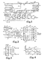
- FIG. 3 Another embodiment of the detecting means 64 is shown in Figure 3.
- a pair of pressure switches 102, 104 are sealingly disposed in line 38 in contact with the pressurized refrigerating fluid vapor 65 flowing therein.
- the pressure switches 102 and 104 may be preset to operate at preset selected established "cut-in” and “cut-out” pressures, respectively, detected in line 38.
- pressure switch 102 detects pressure exceeding the established "cut-in” pressure, it is actuated and operates switch contacts 105 to apply a voltage signal via conductors 108 and 78 to timer 82 for the purposes hereinabove described.
- pressure switch 104 detects pressure below the established "cut-out” pressure, it is actuated and operates switch contacts 107 to apply a voltage signal via conductors 108 and 80 to timer 84 for the purposes hereinabove described. Accordingly, the means of establishment of the single selected system "cut-in” and “cut-out” pressures and the determination of reaching those pressures can be combined, thus eliminating the need for the comparator circuits 74 and 76 and the potentiometers 75 and 77.
Landscapes
- Engineering & Computer Science (AREA)
- Physics & Mathematics (AREA)
- General Physics & Mathematics (AREA)
- Automation & Control Theory (AREA)
- Mechanical Engineering (AREA)
- Thermal Sciences (AREA)
- General Engineering & Computer Science (AREA)
- Air Conditioning Control Device (AREA)
- Control Of Positive-Displacement Pumps (AREA)
- Devices That Are Associated With Refrigeration Equipment (AREA)
- Applications Or Details Of Rotary Compressors (AREA)
Abstract
Description
- This invention relates to an apparatus for increasing the performance of a multi-stage refrigeration or cooling system both in terms of matching load to demand as closely as possible in terms of economic use of all of the compressors.
- In the past, the cycling of stages of a multiple-stage refrigeration or cooling system has been principally accomplished by setting each stage at a successively lower "cut-in" and "cut-out" pressure of the refrigeration fluid flowing in the suction line from the evaporator coil to the compressor(s) or cooling stages. The use of successively lower "cut-in" and "cut-out" pressure ranges for each cooling stage results in an average pressure which is lower than the mean pressure of the pressure differential between the "cut-in" and "cut-out" pressures of the highest stage. Various mechanical and electromechanical systems have been devices to attempt to solve this problem, primarily utilising the successively lower pressure ranges for each successive cooling stage as described above.
- Patents which are typical of the prior art for mechanically or electromechanically controlling refrigeration compressor capacity include the following U.S. Patent Nos: 3,885,938; 3,828,152; 3,719,057; 3,581,519, 3,580,006; 3,552,137; 3,377,816 and 3,792,317.
- It is known in particular from U.S. Patent 3,513,662 to provide in a control means for a cooling system a preselected number of commonly piped compressors having a common suction pressure load; measurement means for generating an increase capacity signal when said suction pressure exceeds a first preselected value and a decrease capacity signal when said suction pressure falls below a second predetermined value;
- time delay means responsive to said measurement means for producing a time delay prior to generating a corresponding cut-in or cut-out signal; and
- selection means for selecting at least one compressor to be energised or deenergised in response to a cut-in or cut-out signal so as to match system capacity to the cooling load.
- In the system of this U.S. patent there is a feed-back control system in which both the fluid flow and the control scheme exhibit a cascaded or serially connected format. In other words the system operates on a LIFO (last-in first-out) strategy in which the ability of the control circuit to energise or deenergise a compressor is entirely dependent upon the status of the other in-line compressors in the system. For example in a three compressor system at any given time the combinations possible are No. 1, 1+2, and 1+2+3 i.e. a total of three combinations equal to the number of compressors. Such a system is subject to the disadvantages above described and also the disadvantage that the compressors are subjected to unequal wear, since the first compressor always takes the maximum load and the third compressor the least load. There is the further disadvantage that at least the first and possibly the second compressor will not be de-energised periodically as recommended by manufacturers. Although it is disclosed in US-A-3 513 662 to even out wear on the individual compressors by interchanging the order of energising the compressors, no specific means have been described for achieving this aim. According to a characterizing feature of the apparatus according to the invention, the selection means includes circuit means for tandemly energising a combination of said compressors from a number of possible combinations that exceeds the number of preselected compressors in the system.
- The U.S. Patent 3717300 (Evaids). This describes a temperature control apparatus for heating hot water by means of electrical resistance elements which are protected in a closed loop and are energised and deenergised by means of a Wheatstone bridge balancing circuit containing a thermistor. The circuit is an integrated electronic circuit which relies upon closely matched resistors, a number of which are temperature dependent. It is inherently subject to malfunction through failure of a component and would be difficult to adapt to purposes other than its intended purpose. The circuit operates on a FIFO strategy (first-in, first-out). In its preferred arrangement, there is deliberate interruption of the circuit even when this is not needed to match demand, the purpose being to distribute the stress caused by long periods of use and to prevent the formation of "hot-spots". Use of such a system in a cooling system utilising a common circulation circuit would be counterproductive in promoting excessive and unnecessary compressor cycling. A modification of the circuit is described in which continuous interruption is not caused. It is said that this modification could be useful for long relay life but is discarded the ground that it would cause the same heating units to be energised for long periods of time thereby developing hot spots and failing to distribute the load. The patent does suggest that the load resistors may be considered as relays for activating cooling devices. There is no suggestion of utilising such a circuit in activating tendemly arranged compressors in a common cooling circuit or for utilising the modified and less preferred circuit arrangement in such a situation.
- The present invention is based upon the realisation of the important advantages to be obtained by utilisation of the strategy defined in the first characteristic feature, e.g. a FIFO strategy, in a cooling system based upon tendemly connected compressors in a common cooling duct and that these advantages can be simply and reliably brought about through an improved control means based upon logic circuits which can ensure safe long term use and ease of maintenance, and which enable the cooling system to operate at close pressure settings giving higher performance and energy saving.
- Thus the invention is further characterised in that the control circuit means comprises,
- status monitoring means connected for receiving said delayed-increase capacity signals and delayed-decrease capacity signals from said time delay means and monitoring and storing compressor operational status, and
- enabling means responsive to said status monitoring means and connected in tandem with said plurality of actuation means for generating a separate output voltage to at least one actuation means corresponding to a compressor of appropriate status in response to delayed-increase capacity signals received from said time delay means, and for discontinuing at least one of said output voltages corresponding to a compressor of appropriate status in response to delayed-decrease capacity signals.
- Preferably the status monitoring means comprises a counter for receiving said delayed-increase and delayed-decrease capacity signals from said time delay means and generating in response thereto one of two corresponding successively repeatable series of cut-in and cut-out control signal outputs, the number of control signal outputs in each series at least equalling the number of cooling stages in the system, and wherein said enabling means comprises a latch circuit for receiving each of said cut-in control signal outputs as "set" signals generating in response thereto a selected one of a single successively repeatable series of cooling stage "on" signals for cutting-in a corresponding cooling stage, said latch circuit further receiving each of said cut-out control signal outputs as "reset" signals removing in response thereto a selected one of said "on" signals from said latch circuit series for cutting-out a corresponding cooling stage, said actuating means being responsive to said "on" signals, and means being provided if necessary for disabling the counter when all of the compressors are on or off.
- In order that the manner in which the above- recited advantages and features of the invention are attained can be understood in detail, a more particular description of the invention may be had by reference to specific embodiments thereof which are illustrated in the appended drawings, which drawings form part of this specification. It is to be noted, however, that the appended drawings illustrate only typical embodiments of the invention and therefore are not to be considered limiting of its scope for the invention may admit to further equally affective embodiments.
- In the drawings:
- Figure 1 is a simplified schematic of a multiple-stage cooling or refrigeration system including the capacity control apparatus according to this invention.
- Figure 2 is a block diagram schematic of the capacity controller circuit shown in Figure 1.
- Figure 3 is a partial schematic representation of another embodiment of a pressure detection means for determining when a selected system "cut-in" and "cut-out" pressure has been reached.
- Figure 4 is a graphical representation of the refrigerating fluid pressure vs. time of a multiple-stage refrigeration or cooling system load operating within the parameters of the capacity control method and apparatus according to the present invention.
- Referring now to Figure 1, the refrigeration system
capacity controller circuit 10 is shown disposed in a multiple-stage refrigeration or cooling system 20 consisting of a plurality of parallel stagedrefrigerant compressors discharge line 22 to acondenser coil 25 where the pressurized refrigerant vapor is condensed to a liquid and then delivered to a receiver vessel 26. From the receiver 26, the liquid refrigerant flows through line 28 and through an expansion device orvalve 30, typically a mechanical expansion valve responding to the temperature insuction line 38 as sensed bytemperature sensing device 32. The temperature signal fromsensor 32 is applied tovalve 30 throughconductor 33 to initiate the expansion valve action. The liquid refrigerant is injected throughexpansion device 30 into theevaporator coil 35 where the liquid refrigerant, encountering the low pressure of the evaporator coil, boils and evaporates thus absorbing heat from the evaporator coil. The hot vaporized refrigerant from the evaporator coil is drawn throughsuction line 38 to the inlet ports of the multiple compressors 12-18. The number of parallel compressors to be staged in the system varies according to the refrigerating or cooling system load. In Figure 1, three compressors are shown in dotted lines as 12, 14 and 16 and an "N"th number of compressors is shown by compressor 18. - A pressure transducer 40 is attached to the
suction line 38 and determines the refrigerant vapor pressure withinsuction line 38 and generates an electrical signal representative of the measured pressure. The signal is applied throughconductor 42 as an input to thecapacity controller circuit 10, which will be hereinafter described in greater detail. The output of thecontroller circuit 10 is a plurality of outputs corresponding to the number of the plurality of cooling stages or parallel compressors staged in the system. Accordingly, there are a corresponding "N" number of outputs from thecapacity controller circuit 10 labelled 1, 2, 3 and N. Thecontroller circuit output 1 is applied throughconductor 56 to the coil of a relay 44 which controls relay switch contacts 45 for applying AC power viaconductors 52 and 54 to thefirst compressor 12 for energizing the compressor when it is desired to cut the compressor into the system. Similarly, the 2, 3 and N outputs of the capacity controller circuit are applied throughconductors relays closing switches 47, 49 and 51, respectively, for successively applying AC electrical power to the 2, 3, and N compressors, respectively, for either turning on or turning off the compressors in a staged sequence. - Referring now to Figures 1, 2 and 4, the operation of the
capacity controller circuit 10 will be described in greater detail. The pressure detecting means or transducer 40 is shown sealingly inserted into therefrigerant vapor flow 65 insuction line tubing 38. Pressure transducer 40 may be any conventional pressure detecting means for generating an electrical signal representative of the pressure withinline 38. The pressure signal from transducer 40 is applied throughconductors 42 and 70 to the positive input of a comparator circuit 74, and throughconductors potentiometer 75 to the negative input of the comparator circuit 74. Similarly, a voltage is applied through a voltage varying means such aspotentiometer 77 to the positive input of the comparator circuit 76 to set a predetermined "cut-out" pressure for the system. Comparator circuit 74 compares the predetermined cooling system "cut-in" pressure (set by potentiometer 75) against the suction line pressure continuously detected by pressure transducer 40 and produces a "cut-in" electrical signal when the measured pressure exceeds the predetermined "cut-in" pressure. Comparator circuit 76 compares the predetermined cooling system "cut-out" pressure (set by potentiometer 77) against the pressure continuously detected by the pressure transducer 40 and produces a "cut-out" electrical signal when the detected system pressure exceeds the predetermined "cut-out" pressure. The combination of transducer 40,potentiometers - The "cut-in" signal of comparator 74 is applied through
conductor 78 to a timer 82 which generates an output electrical control signal after a first predetermined minimum time delay. The delayed time output control signal is applied throughconductor 86 as an input to a counter 90. Counter 90 is a conventional counter circuit that generates a successive plurality ofoutputs 1 to N corresponding to the number of staged parallel compressors in the system. Each delayed control signal received from timer 82 by counter 90 will cause a counter output signal to appear at one of the series ofsuccessive counter outputs conductor 95 as a "set" input to alatch circuit 94. - The
latch circuit 94 is of conventional solid- state design and generates a series of repeatable successive "cut-in" electrical control signals atoutputs conductors compressor control relays conductors 95 from the 1, 2, 3 or N outputs of counter 90. For example, if the counter 90 has an output signal atoutput 1 applied through aconductor 95 as a "set" input to latchcircuit 94,latch circuit 94 will generate a control signal output voltage at its 1 output (conductor 56). Similarly, output signals from counter 90 appearing in a series successively at 2, 3 and N are applied throughconductors 94 as repeatable successive "set" inputs to latchcircuit 94, thereby generating "cut-in" or turn on control signals appearing atoutputs conductors conductors relays multiple compressors - Similarly, the "cut-out" output signal of comparator 76 is applied through
conductor 80 to atimer 84.Timer circuit 84 generates a delayed "cut-out" electrical control signal after a predetermined time delay. The control signal is applied throughconductor 88 as an input to anothercounter circuit 92.Counter 92 may be identical to the counter 90 hereinabove described. Each successive delayed "cut-out" control signal received fromtimer circuit 84 generates one of a series of repeatable successive electrical signals at counter 92outputs conductors 93 as "reset" inputs to latchcircuit 94. Receipt of the successive series of delayed "cut-out" control signals from counter 92 causes thelatch circuit 94 to be reset in the succession in which the counter signals are received. - For example, upon receipt of a
counter 92output 1 signal applied throughconductor 93 as a "reset" input to latchcircuit 94, thelatch 94 output at 1 will be reset and no voltage will appear onconductor 56 thus de-energizing relay 44, opening relay switch contacts 45 and "cutting-out" thefirst compressor 12, which has run the longest. Accordingly,successive counter 92 signals received fromoutputs circuit 94 will successively reset the latch circuit and remove the latch circuit voltage outputs appearing atlines conductors compressors - In addition, the
latch circuit outputs conductors conductors 99 as inputs to a conventional ANDgate 96. When all of thelatch circuit outputs gate 96 generates an output signal applied throughconductor 97 to counter 90 to disable counter 90 at its last count and prevent further delayed "cut-in" electrical signals received from timer 82 from generating further counter 90 output electrical signals for application to thelatch circuit 94. Similarly, thelatch circuit outputs conductors 101 as inputs to a conventional NORgate 98. NORgate 98 will generate an electrical output signal to be applied throughconductor 103 to disable counter 92 when all of thelatch circuit outputs gate 98 disables counter 92 and prevents any further "cut-out" delayed signals received fromtimer 84 from triggering anyfurther counter 92 output signals to be applied as reset inputs to latchcircuit 94. - The operation of the
capacity controlling circuit 10 can now further be described with reference to Figures 1, 2 and 4. The graph of Figure 4 depicts the system refrigerating fluid vs. time and is represented bypressure trace 121. The selected "cut-in" pressure represented byline 120 is set for the system bypotentiometer 75 as one input to the comparator 74, as hereinabove described. The selected "cut-out" pressure represented byline 130 is set bypotentiometer 77 as one input to comparator 76, as hereinabove described. The desired system suction line pressure range ΔP has been selected for optimum efficiency of the system. The timer 82, as hereinabove described, establishes a predetermined delay time which is represented by the time interval ΔT, and the delay time established bytimer circuit 84 is represented by the shorter time interval Δt. Assuming thatcompressors point 122 and comparator 74 will generate an electrical "cut-in" signal to be applied to the timer 82. - The comparator signal output occurs at
point 122 which is the point at which thesuction line pressure 121 rises above or exceeds the predetermined cut-in system pressure and establishes the beginning of the delay time AT of timer 82. The suction pressure may continue to rise as shown in Figure 4 until timer 82 generates its delayed "cut-in" electrical control signal which is applied to counter 90, and sincecompressors output 3 which is then applied through aconductor 95 as a "set" input to latchcircuit 94. Receipt of the delayed "cut-in" signal fromoutput 3 of timer 82 by thelatch circuit 94 causes a positive voltage to appear at latch output 3 (conductor 60) which is applied to relay 48 for energizing the relay, closings relay switch 49 and "cutting-in" thethird compressor 16, which has been "turned off" the longest time period. The end of the predetermined time delay, ΔT, established by timer 82, occurs at point 124, and the third compressor or cooling stage now in the system adds cooling capacity and returns the pressure to the desired operating pressure line pressure to the desired operating pressure differential ΔP range established bypressures - In the event the suction pressure (121) declines because of over-capacity in the system, and falls below the predetermined "cut-out" pressure represented by
line 130, then comparator 76 will generate a "cut-out" signal applied to thetimer 84 occuring atpoint 126, which begins the established time delay Δt. When the predetermined time delay At has elapsed,timer 84 generates a "cut-out" electrical control signal applied throughconductor 88 as an input to thecounter 92. Thecounter 92, in response to the received signal, will generate an output signal on line I applied through aconductor 93 to latchcircuit 94 as a "reset" input. The counter reset signal applied to latchcircuit 94 will "reset" output line I of the latch circuit, thereby removing the positive voltage output atconductor 56 and de-energizing relay 44, opening switch contacts 45 and "cutting-out" compressor 12 (which has been operating the longest time period) from the system, as reflected at 128, the end of the delay At and the point where the suction pressure again begins to increase. Whencompressor 12 is "cut-out" of the system, the suction line pressure begins to increase until it returns to the desired operating range between thepressure differentials - In this way the multiple staged compressors can be "cut-in" or "cut-out" of the system to increase or decrease refrigeration capacity depending on the system refrigeration load. The compressor that has operated the longest will always be the first to be "cut-out" when the system capacity needs diminish, and the compressor that has not operated the longest will be the next to be "cut-in" when the system capacity needs increase.
- The
timers 82 and 84 and counters 90 and 92 "remember" the length of their respective time delays, AT and Δt. For example, referring to Figures 1, 2 and 4, if AT is five (5) minutes, and At is five (5) seconds, ifsuction pressure 121 rises above the "cut-in" pressure (120) atpoint 122, the five (5) minute AT period begins. However, ifsuction pressure trace 121 had dropped back below "cut-in"pressure 120 after only two (2) minutes had elapsed (or before reaching point 124), the "cut-in" signal from comparator 74 will cease, disabling timer 82. Similarly, ifsuction pressure trace 121 falls below the "cut-out"pressure 130 as atpoint 126, the five (5) second At period begins. However, if the suction pressure (121) increases and rises above "cut-out" pressure (130) after only three (3) seconds, the "cut-out" signal from comparator 76 will cease and disabletimer 84, and no delayed "cut-out" signal will be sent to counter 92. Accordingly, no delayed "cut-in" signal will be addressed to counter 90. Therefore, no additional compressor or cooling stage will be "cut-in", but the next time thesuction pressure 121 exceeds the "cut-in" pressure, timer 82 will again be energized and will produce a delayed "cut-in" signal after only three (3) minutes (the balance of AT left over from the last AT period) and "cut-in" or turn on the next compressor or cooling stage of the system. Similarly, the next time thepressure trace 121 decreases to fall below the "cut-out" pressure,timer 84 will again be enabled and will produce a delayed "cut-out" signal after only two (2) seconds (the balance of At left over from the last At period) and "cut-out" or turn off the compressor which has run the longest. - The refrigeration capacity control circuit herein disclosed may also be utilized in controlling multiple-stage refrigeration or cooling systems having multi-cylinder compressors that are staged by controlling the compression of a plurality of compressor cylinders using conventional control valves by having
controller 10 outputs control the utilization of the cooling stages by controlling the cylinders used by the compressors in the system. In addition, it is important to understand that while the system above described in Figures 1, 2 and 4 uses a separate time delay after determination of the reaching of the established "cut-in" or "cut-out" pressures, only a single time delay is necessary to enable selection of successive cooling stages utilizing a single selected "cut-in" system pressure and a single selected "cut-out" system pressure. For instance, in Figure 2, the output of "cut-out" comparator 76 could be applied to timer 82 and utilize a single delay time for both "cut-in" and "cut-out" determinations. Further, the ΔP differential between "cut-in" pressure 120 (Figure 4) and "cut-out"pressure 130 may be large or small, depending on the system design and the best system operating pressure. In certain systems, the ΔP could be set at zero, with the "cut-in" and "cut-out" pressures being established at the same value. - Another embodiment of the detecting
means 64 is shown in Figure 3. A pair of pressure switches 102, 104 are sealingly disposed inline 38 in contact with the pressurized refrigeratingfluid vapor 65 flowing therein. The pressure switches 102 and 104 may be preset to operate at preset selected established "cut-in" and "cut-out" pressures, respectively, detected inline 38. Whenpressure switch 102 detects pressure exceeding the established "cut-in" pressure, it is actuated and operatesswitch contacts 105 to apply a voltage signal viaconductors pressure switch 104 detects pressure below the established "cut-out" pressure, it is actuated and operates switch contacts 107 to apply a voltage signal viaconductors timer 84 for the purposes hereinabove described. Accordingly, the means of establishment of the single selected system "cut-in" and "cut-out" pressures and the determination of reaching those pressures can be combined, thus eliminating the need for the comparator circuits 74 and 76 and thepotentiometers - While the above description of the preferred embodiments has been made with particular reference to a multiple-stage refrigeration system using parallel staged compressors or staged multiple-cylinder compresssors, it should be appreciated that the capacity controlling method and apparatus herein described may be utilized in controlling the capacity of any multiple-stage cooling system such as air- conditioning systems utilizing chilled water and the like, by controlling cooling stages in those systems by controlling utilization of water circulating pumps or controlling the utilization of vanes in centrifugal pumps and the like.
Claims (4)
Priority Applications (1)
| Application Number | Priority Date | Filing Date | Title |
|---|---|---|---|
| AT80901475T ATE11338T1 (en) | 1979-07-31 | 1980-07-31 | APPARATUS FOR CONTROLLING THE CAPACITY OF A MULTISTAGE REFRIGERATION SYSTEM. |
Applications Claiming Priority (2)
| Application Number | Priority Date | Filing Date | Title |
|---|---|---|---|
| US6252579A | 1979-07-31 | 1979-07-31 | |
| US62525 | 1993-05-11 |
Publications (3)
| Publication Number | Publication Date |
|---|---|
| EP0034591A1 EP0034591A1 (en) | 1981-09-02 |
| EP0034591A4 EP0034591A4 (en) | 1982-01-26 |
| EP0034591B1 true EP0034591B1 (en) | 1985-01-16 |
Family
ID=22043052
Family Applications (1)
| Application Number | Title | Priority Date | Filing Date |
|---|---|---|---|
| EP80901475A Expired EP0034591B1 (en) | 1979-07-31 | 1981-02-24 | Apparatus for controlling capacity of a multiple-stage cooling system |
Country Status (8)
| Country | Link |
|---|---|
| EP (1) | EP0034591B1 (en) |
| JP (1) | JPS56501097A (en) |
| AT (1) | ATE11338T1 (en) |
| AU (1) | AU543220B2 (en) |
| CA (1) | CA1158745A (en) |
| DE (1) | DE3069971D1 (en) |
| WO (1) | WO1981000446A1 (en) |
| ZA (1) | ZA804656B (en) |
Families Citing this family (8)
| Publication number | Priority date | Publication date | Assignee | Title |
|---|---|---|---|---|
| IT1168497B (en) * | 1981-07-13 | 1987-05-20 | Necchi Spa | CONDENSER MOTOR-COMPRESSOR GROUP FOR REFRIGERATION CYCLES |
| FR2521272B1 (en) * | 1982-02-09 | 1985-12-13 | Bonnet Ets | CONTROL PROGRAMMER FOR MULTI-COMPRESSOR REFRIGERATION PLANT |
| JPS58145519A (en) * | 1982-02-20 | 1983-08-30 | Sanden Corp | Controller for cooler of vehicle |
| US4580071A (en) * | 1983-07-28 | 1986-04-01 | Mitsubishi Denki Kabushiki Kaisha | Generator cooling apparatus |
| US4633672A (en) * | 1985-02-19 | 1987-01-06 | Margaux Controls, Inc. | Unequal compressor refrigeration control system |
| DE253928T1 (en) * | 1986-07-22 | 1988-10-13 | Margaux Controls Inc., San Jose, Calif. | CONTROL SYSTEM FOR COMPRESSORS OF COOLING SYSTEMS. |
| IL85537A0 (en) * | 1987-02-25 | 1988-08-31 | Prestcold Ltd | Refrigeration systems |
| FR2617581B1 (en) * | 1987-06-30 | 1989-09-29 | Henriot Jean Luc | REFRIGERATION SYSTEM FOR AN APPARATUS FOR FREEZING AND PRESERVING FOOD PRODUCTS |
Citations (2)
| Publication number | Priority date | Publication date | Assignee | Title |
|---|---|---|---|---|
| US3744932A (en) * | 1971-04-30 | 1973-07-10 | Prevett Ass Inc | Automatic sequence control system for pump motors and the like |
| FR2165138A5 (en) * | 1971-12-20 | 1973-08-03 | Laks Maurice |
Family Cites Families (5)
| Publication number | Priority date | Publication date | Assignee | Title |
|---|---|---|---|---|
| US2782350A (en) * | 1953-08-06 | 1957-02-19 | Whirlpool Seeger Corp | Electrical circuit for multiple motor system |
| US3513662A (en) * | 1968-11-12 | 1970-05-26 | Armour & Co | Feedback control system for sequencing motors |
| US3717300A (en) * | 1971-10-14 | 1973-02-20 | Athena Controls | Temperature control apparatus with a cyclical distributor |
| US4003370A (en) * | 1975-10-14 | 1977-01-18 | American Hospital Supply Corporation | Blood pressure monitor system and method |
| GB1553217A (en) * | 1976-08-31 | 1979-09-26 | Isovel Ltd | Refrigerating apparatus |
-
1980
- 1980-07-29 CA CA000357253A patent/CA1158745A/en not_active Expired
- 1980-07-31 DE DE8080901475T patent/DE3069971D1/en not_active Expired
- 1980-07-31 JP JP50180680A patent/JPS56501097A/ja active Pending
- 1980-07-31 ZA ZA00804656A patent/ZA804656B/en unknown
- 1980-07-31 WO PCT/US1980/000971 patent/WO1981000446A1/en not_active Ceased
- 1980-07-31 AT AT80901475T patent/ATE11338T1/en not_active IP Right Cessation
- 1980-07-31 AU AU61294/80A patent/AU543220B2/en not_active Ceased
-
1981
- 1981-02-24 EP EP80901475A patent/EP0034591B1/en not_active Expired
Patent Citations (2)
| Publication number | Priority date | Publication date | Assignee | Title |
|---|---|---|---|---|
| US3744932A (en) * | 1971-04-30 | 1973-07-10 | Prevett Ass Inc | Automatic sequence control system for pump motors and the like |
| FR2165138A5 (en) * | 1971-12-20 | 1973-08-03 | Laks Maurice |
Also Published As
| Publication number | Publication date |
|---|---|
| CA1158745A (en) | 1983-12-13 |
| AU6129480A (en) | 1981-03-03 |
| JPS56501097A (en) | 1981-08-06 |
| WO1981000446A1 (en) | 1981-02-19 |
| DE3069971D1 (en) | 1985-02-28 |
| EP0034591A4 (en) | 1982-01-26 |
| ZA804656B (en) | 1982-02-24 |
| EP0034591A1 (en) | 1981-09-02 |
| AU543220B2 (en) | 1985-04-04 |
| ATE11338T1 (en) | 1985-02-15 |
Similar Documents
| Publication | Publication Date | Title |
|---|---|---|
| US4831832A (en) | Method and apparatus for controlling capacity of multiple compressors refrigeration system | |
| US4612776A (en) | Method and apparatus for controlling capacity of a multiple-stage cooling system | |
| US4951475A (en) | Method and apparatus for controlling capacity of a multiple-stage cooling system | |
| US5265434A (en) | Method and apparatus for controlling capacity of a multiple-stage cooling system | |
| US5067326A (en) | Method and apparatus for controlling capacity of a multiple-stage cooling system | |
| US4679404A (en) | Temperature responsive compressor pressure control apparatus and method | |
| US4628700A (en) | Temperature optimizer control apparatus and method | |
| KR100190148B1 (en) | Fuzzy Logic Control Circuit of Liquid Injection for Motor Cooling | |
| US4193781A (en) | Head pressure control for heat reclaim refrigeration systems | |
| US4535602A (en) | Shift logic control apparatus for unequal capacity compressors in a refrigeration system | |
| US4537038A (en) | Method and apparatus for controlling pressure in a single compressor refrigeration system | |
| US5042264A (en) | Method for detecting and correcting reversing valve failures in heat pump systems having a variable speed compressor | |
| US4535607A (en) | Method and control system for limiting the load placed on a refrigeration system upon a recycle start | |
| US5077983A (en) | Method and apparatus for improving efficiency of a pulsed expansion valve heat pump | |
| EP0151493A2 (en) | Room-warming/cooling and hot-water supplying heat pump apparatus | |
| US4538422A (en) | Method and control system for limiting compressor capacity in a refrigeration system upon a recycle start | |
| CA1264364A (en) | Automatic anti-surge control for dual centrifugal compressor system | |
| WO1988006703A1 (en) | Refrigeration systems | |
| KR900005977B1 (en) | Protective capacity control system for a refrigeration system | |
| WO2013016436A1 (en) | Loading and unloading of compressors in a cooling system | |
| US4326387A (en) | Fluidic time delay system | |
| EP0034591B1 (en) | Apparatus for controlling capacity of a multiple-stage cooling system | |
| US4825662A (en) | Temperature responsive compressor pressure control apparatus and method | |
| WO2005022050A2 (en) | Boosted air source heat pump | |
| CA2086398C (en) | Automatic chiller stopping sequence |
Legal Events
| Date | Code | Title | Description |
|---|---|---|---|
| PUAI | Public reference made under article 153(3) epc to a published international application that has entered the european phase |
Free format text: ORIGINAL CODE: 0009012 |
|
| AK | Designated contracting states |
Designated state(s): AT CH DE FR GB LI LU NL SE |
|
| 17P | Request for examination filed |
Effective date: 19810817 |
|
| GRAA | (expected) grant |
Free format text: ORIGINAL CODE: 0009210 |
|
| AK | Designated contracting states |
Designated state(s): AT CH DE FR GB LI LU NL SE |
|
| PG25 | Lapsed in a contracting state [announced via postgrant information from national office to epo] |
Ref country code: AT Effective date: 19850116 |
|
| REF | Corresponds to: |
Ref document number: 11338 Country of ref document: AT Date of ref document: 19850215 Kind code of ref document: T |
|
| REF | Corresponds to: |
Ref document number: 3069971 Country of ref document: DE Date of ref document: 19850228 |
|
| ET | Fr: translation filed | ||
| PG25 | Lapsed in a contracting state [announced via postgrant information from national office to epo] |
Ref country code: LU Free format text: LAPSE BECAUSE OF NON-PAYMENT OF DUE FEES Effective date: 19850731 |
|
| PLBE | No opposition filed within time limit |
Free format text: ORIGINAL CODE: 0009261 |
|
| STAA | Information on the status of an ep patent application or granted ep patent |
Free format text: STATUS: NO OPPOSITION FILED WITHIN TIME LIMIT |
|
| 26N | No opposition filed | ||
| PG25 | Lapsed in a contracting state [announced via postgrant information from national office to epo] |
Ref country code: LI Effective date: 19860731 Ref country code: CH Effective date: 19860731 |
|
| PGFP | Annual fee paid to national office [announced via postgrant information from national office to epo] |
Ref country code: NL Payment date: 19860731 Year of fee payment: 7 |
|
| PG25 | Lapsed in a contracting state [announced via postgrant information from national office to epo] |
Ref country code: SE Effective date: 19860801 |
|
| REG | Reference to a national code |
Ref country code: CH Ref legal event code: PL |
|
| PG25 | Lapsed in a contracting state [announced via postgrant information from national office to epo] |
Ref country code: NL Effective date: 19880201 |
|
| NLV4 | Nl: lapsed or anulled due to non-payment of the annual fee | ||
| PG25 | Lapsed in a contracting state [announced via postgrant information from national office to epo] |
Ref country code: FR Free format text: LAPSE BECAUSE OF NON-PAYMENT OF DUE FEES Effective date: 19880331 |
|
| REG | Reference to a national code |
Ref country code: FR Ref legal event code: ST |
|
| PGFP | Annual fee paid to national office [announced via postgrant information from national office to epo] |
Ref country code: DE Payment date: 19890929 Year of fee payment: 10 |
|
| PG25 | Lapsed in a contracting state [announced via postgrant information from national office to epo] |
Ref country code: DE Effective date: 19910403 |
|
| PGFP | Annual fee paid to national office [announced via postgrant information from national office to epo] |
Ref country code: GB Payment date: 19930721 Year of fee payment: 14 |
|
| PG25 | Lapsed in a contracting state [announced via postgrant information from national office to epo] |
Ref country code: GB Effective date: 19940731 |
|
| EUG | Se: european patent has lapsed |
Ref document number: 80901475.6 Effective date: 19870812 |
|
| GBPC | Gb: european patent ceased through non-payment of renewal fee |
Effective date: 19940731 |