EP0033991B1 - Record player - Google Patents
Record player Download PDFInfo
- Publication number
- EP0033991B1 EP0033991B1 EP81200100A EP81200100A EP0033991B1 EP 0033991 B1 EP0033991 B1 EP 0033991B1 EP 81200100 A EP81200100 A EP 81200100A EP 81200100 A EP81200100 A EP 81200100A EP 0033991 B1 EP0033991 B1 EP 0033991B1
- Authority
- EP
- European Patent Office
- Prior art keywords
- pick
- arm
- control element
- path
- coupling portion
- Prior art date
- Legal status (The legal status is an assumption and is not a legal conclusion. Google has not performed a legal analysis and makes no representation as to the accuracy of the status listed.)
- Expired
Links
Images


Classifications
-
- G—PHYSICS
- G11—INFORMATION STORAGE
- G11B—INFORMATION STORAGE BASED ON RELATIVE MOVEMENT BETWEEN RECORD CARRIER AND TRANSDUCER
- G11B3/00—Recording by mechanical cutting, deforming or pressing, e.g. of grooves or pits; Reproducing by mechanical sensing; Record carriers therefor
- G11B3/02—Arrangements of heads
- G11B3/08—Raising, lowering, traversing otherwise than for transducing, arresting, or holding-up heads against record carriers
- G11B3/085—Raising, lowering, traversing otherwise than for transducing, arresting, or holding-up heads against record carriers using automatic means
- G11B3/08535—Driving the head
- G11B3/08538—Driving the head the head being driven by the same means as the record can
- G11B3/08541—Driving the head the head being driven by the same means as the record can for pivoting pick-up arms
- G11B3/08545—Driving the head the head being driven by the same means as the record can for pivoting pick-up arms driven by cams
Definitions
- the control element After the pick-up arm has been returned to an end position through a movement in the first direction, the control element, after being locked, and thus the pick-up arm are slightly pivoted back under the influence of the control spring. Thus the pick-up arm is moved to the rest position with a detour, which results in loss of time and an unsteady movement of the pick-up arm. Further as a result of inaccurate adjustment or wear it is possible that the control element will not be locked correctly after tensioning of the control spring, so that the pick-up arm is again moved in the second direction from the rest position towards the turntable, which is undesirable.
- the frame carries guide means for the control element, which guide means, when the rod is moved in the first and second directions during control of the pick-up arm in the second direction of movement, cause the coupling portion of the control element to follow first and second paths respectively, which paths are substantially concentric with the axis of the pick-up arm spindle, the first path being situated at a greater radial distance from said axis than the second path and the coupling portion of the control element being engageable with the coupling portion of the pick-up arm lever in the second path only.
- the record player shown in Figure 1 comprises a frame 1 on which a turntable 2 is mounted for rotation about an axis 3.
- a pick-up arm spindle 4 is journalled in the frame 1, which spindle extends through a deck plate 5 of the frame 1 and is rigidly connected to a pick-up arm 6.
- the pick-up arm spindle 4 extends substantially parallel to the axis of rotation 3 and at right angles to the deck plate 5.
- a pick-up element 7 is secured to the pick-up arm 6. In the rest position of the pick-up arm 6, shown in Figure 1, the pick-up arm is situated on a support 8.
- the pick-up arm can be secured to the support 8 by means of a latch 9.
- control elements which are usually provided for controlling the record player, such as a control knob 10 for starting and stopping the record player operation and a control knob 11 for selecting the speed of rotation of the turntable and at the same time setting the position to which the pick-up arm 6 is automatically moved in a manner to be described hereinafter.
- actuating lever 12 on the deck plate, by means of which lever the pick-up arm 6 can be lifted or lowered relative to the turntable 2.
- the second portion 15 of the pick-up arm lever 13 comprises a pawl 24 which extends substantially parallel to the axis of rotation 3 and whose function will also be described in more detail hereinafter.
- Figures 2-5 represent a setting for a 17-cm, 35-rpm record for which the recess 42 is operative.
- a broken line in Figure 4 shows how the pin 57, after rotation of the control disc through approximately 315°, has passed a point 81 which constitutes an end point of the second path and which is situated near the end of the second ridge 64.
- the connecting rod 47 Adjacent the slot 48 the connecting rod 47 is formed with a ramp surface which rises in the direction of the spindle 46 and is such that in the position of the connecting rod 47 shown in Figures 2 and 6 the support 84 is in lowest position relative to the deck plate 5. In this position the support 84 is spaced from the underside of the pick-up arm 6.
- the connecting rod 47 moves in the direction of the arrow E, the projections 85 are lifted towards the deck plate 5 by the ramp surface of the connecting rod 47 against the pressure of the spring 86, which results in an upward movement of the support 84 relative to the deck plate 5.
- This upward movement results in the support 84 lifting the pick-up arm 6, so that the pick-up arm 6 and the pick-up element 7 are entirely clear of the turntable 2 during control by the control disc 27.
- the said coupling means are actuated so that the gear wheel 27 again meshes with the teeth of the control disc 27. Subsequently, the control disc 27 again starts to rotate in the direction of the arrow A. The pin 57 is then moved from the starting point 78 in the first path to the end point 79. Owing to the ramp surface of the connecting rod near the slot 48 the pin 49 is raised so that the support 84 lifts the pick-up arm 6. The pick-up element 7 is thereby moved clear of the record on the turntable 2.
Description
- The invention relates to a record player having a frame on which a turntable is mounted for rotation and in which a pick-up arm spindle is journalled, which spindle is rigidly connected to a pick-up arm and to a pick-up arm lever, the frame also carrying a rotary control member by which the pick-up arm can be controlled in a first direction of movement about the axis of the spindle away from the centre of the turntable and in a second direction of movement about the axis of the spindle towards the centre of the turntable, and which for this purpose is connected to a rod which is movable translationally in reciprocal first and second directions and to which is connected a control element which comprises a coupling portion which, during control of the pick-up arm in the second direction of movement and when the rod is moving in the second direction is engageable with a coupling portion of the pick-up arm lever, for controlling the pick-up arm in the second direction of movement.
- A record player of this type is known from United States Patent Specification 3,342,499. In this known record player the control element is rotatable about the pick-up arm spindle under the influence of a control spring which is connected to the control element, by which rotation the pick-up arm is movable in the second direction from a rest position towards the centre of the turntable. If the pick-up arm of this known record player is moved in the first direction towards the rest position under the influence of the control member, the control spring of the control element is tensioned again. In order to prevent the pick-up arm, after having reached the rest position, from being moved again in the second direction, a locking mechanism ensures that the control element cannot rotate after the control spring has been tensioned. In order to enable the control element to be locked, some clearance is necessary between a catch provided on the control element and the locking mechanism.
- After the pick-up arm has been returned to an end position through a movement in the first direction, the control element, after being locked, and thus the pick-up arm are slightly pivoted back under the influence of the control spring. Thus the pick-up arm is moved to the rest position with a detour, which results in loss of time and an unsteady movement of the pick-up arm. Further as a result of inaccurate adjustment or wear it is possible that the control element will not be locked correctly after tensioning of the control spring, so that the pick-up arm is again moved in the second direction from the rest position towards the turntable, which is undesirable.
- It is the object of the invention to effect control of the pick-up arm of such a record player in such a way that the pick-up arm is moved to the rest position in a rapid and reliable manner.
- According to the invention the frame carries guide means for the control element, which guide means, when the rod is moved in the first and second directions during control of the pick-up arm in the second direction of movement, cause the coupling portion of the control element to follow first and second paths respectively, which paths are substantially concentric with the axis of the pick-up arm spindle, the first path being situated at a greater radial distance from said axis than the second path and the coupling portion of the control element being engageable with the coupling portion of the pick-up arm lever in the second path only. Thus, since during the pick-up arm movement in the first direction the coupling portion of the control element is situated in the first path which is spaced from the second path, erroneous engagement of the said coupling portions of the control element and the pick-up arm lever is not possible.
- This ensures that after the pick-up arm has been returned by a movement in the first direction, the pick-up arm is positioned in the rest position in a direct and stable manner.
- Moving the pick-up arm again in the second direction towards the turntable is possible only after a deliberate starting operation, i.e. a movement of the coupling portion of the control element from the first path to the second path.
- It is to be noted that it is known from United States Patent Specification 3,848,875 to guide the coupling portion of a control element in a record player such a way that coupling is obtained in a specific part of the path. However, in that case there is no question of two paths which are spaced from each other and which are concentric with the axis of the pick-up arm spindle, so that the risk of re-coupling in the rest position still exists.
- In a preferred embodiment of the invention resilient means are provided by which the control element is movable to bring the coupling portion of this element from an end point of the second path to a point in the first path. The resilient means ensure that, when the end point of the second path is reached during the movement of the control element in the second path, the control element is always moved into the first path. In this way it is achieved that after disengagement of the two coupling portions the coupling portions cannot erroneously engage again.
- In this preferred embodiment it is of advantage if the control element is pivotably connected to the rod and the resilient means tend to pivot the control element with the coupling portion relative to the rod.
- This results in a simple reliably operating construction which is capable of effecting the said disengagement of the coupling portions in an effective manner.
- In this embodiment it is also advantageous if the coupling portion of the control element is pivotably connected to the other portion of the control element and the resilient means are arranged between the coupling portion and the rod.
- Thus, after the pick-up arm has completed the movement in the second direction, the two coupling portions can readily disengage owing to the pivotal movement of the coupling portion of the control element.
- In this respect it is advantageous if the guide means are constituted by at least one arcuate ridge which is concentric with the pick-up arm spindle. The sides of this ridge constitute simple easy-to-mount guide means.
- In view of the foregoing it is of advantage if a first arcuate ridge partially defines a sector of circle and a second arcuate ridge is situated entirely within said sector, the first and the second path being respectively defined by one of the sides of the ridges which face towards each other and by one of the sides which face away from each other.
- The ridges may, for example, be provided in a simple yet accurate manner by injection-moulding if the ridges are integral with the frame.
- In a further embodiment of the invention displacement means are provided by which the coupling portion of the control element is movable from an end point of the first path to a starting point of the second path. Thus, the coupling portions of the control element and the pick-up arm lever can be coupled only after performing a deliberate operation, namely the actuation of the displacement means.
- In order to enable the control element to be moved from the first path into the second path by the displacement means it is preferred that the displacement means comprise a starting spring which is movable relative to the control element and whose force is greater than the force of the said resilient means.
- In this respect it is found to be advantageous if the displacement means further comprise a starting lever which is pivotable against spring force into a latched position, in which position the starting spring presses against the control element.
- In order to enable the control element to return into the first path a preferred embodiment of the invention is characterized in that after the coupling portion of the control element has moved into the second path the starting lever can be released from the latched position by the rod.
- The invention will now be described in more detail with reference to the drawings, which show some embodiments to which the invention is not limited.
- In the drawings:
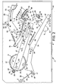
- Figure 1 is a perspective view of a record player in accordance with the invention;
- Figure 2 is an underneath view, taken on the line II-II in Figure 1, of those record player parts which are relevant to the invention, the control disc being in the rest position.
- Figure 3 is an underneath view similar to Figure 2 but showing a situation in which the starting lever has been pivoted into the locked position, the control disc has been rotated through approximately 180° and the pick-up arm is still in the rest position,
- Figure 4 is an underneath view similar to Figure 2 but showing the control disc rotated through approximately 315° and the pick-up arm pivoted relative to the turntable into a set-down position,
- Figure 5 is an underneath view similar to Figure 2 but showing the control disc rotated through approximately 180° and the pick-up arm returned to the rest position,
- Figure 6 is a cross-sectional view on an enlarged scale, taken on the line VI-VI in Figure 2,
- Figure 7 is an underneath view of part of a second embodiment of a record player in accordance with the invention, and
- Figure 8 is an underneath view of part of a third embodiment of a record player in accordance with the invention.
- The record player shown in Figure 1 comprises a
frame 1 on which aturntable 2 is mounted for rotation about anaxis 3. A pick-up arm spindle 4 is journalled in theframe 1, which spindle extends through adeck plate 5 of theframe 1 and is rigidly connected to a pick-up arm 6. The pick-up arm spindle 4 extends substantially parallel to the axis ofrotation 3 and at right angles to thedeck plate 5. A pick-up element 7 is secured to the pick-up arm 6. In the rest position of the pick-up arm 6, shown in Figure 1, the pick-up arm is situated on asupport 8. The pick-up arm can be secured to thesupport 8 by means of a latch 9. - On the
deck plate 5 of theframe 1 there are arranged a number of control elements which are usually provided for controlling the record player, such as acontrol knob 10 for starting and stopping the record player operation and acontrol knob 11 for selecting the speed of rotation of the turntable and at the same time setting the position to which the pick-up arm 6 is automatically moved in a manner to be described hereinafter. There is further provided an actuatinglever 12 on the deck plate, by means of which lever the pick-up arm 6 can be lifted or lowered relative to theturntable 2. - As is shown in Figure 2, the pick-
up arm spindle 4 is rigidly connected to a pick-up arm lever 13 underneath thedeck plate 5. The rest position of the pick-up arm 6 is schematically represented in Figure 2. The pick-up arm lever 13, like most of the parts to be described hereinafter, of the control mechanism for controlling the pick-up arm 6, is preferably made of a plastic and extends substantially parallel to thedeck plate 5. The pick-up arm lever 13 comprises afirst portion 14 and asecond portion 15. Near its free end theportion 14 comprises apawl 16 which extends substantially parallel to the axis ofrotation 3 and constitutes a coupling portion, whose function is to be described in more detail hereinafter. Also mounted on theportion 14 is atorsion spring 17 having turns are arranged around apin 18 which is integral with theportion 14. Thespring 17 compriseslimbs abutments portion 14, thelimb 19 comprising afree end portion 23 which extends substantially parallel to the axis ofrotation 3 over some distance and which also constitutes a coupling portion whose function is to be described in more detail hereinafter. - Near its free end the
second portion 15 of the pick-up arm lever 13 comprises apawl 24 which extends substantially parallel to the axis ofrotation 3 and whose function will also be described in more detail hereinafter. - In a manner not shown, the
frame 1 carries a drive motor for driving theturntable 2. By means of thecontrol knob 10 the motor can be started or stopped, thereby then bringing theturntable 2 into rotation or to a standstill respectively. By means of thecontrol knob 11, in a manner not shown, the speed of the turntable can be set to 33 or 45 revolutions per minute, as required. When theturntabie 2 is driven, aspindle 25 which is rigidly connected to theturntable 2 is also made to rotate, the central axis of said spindle coinciding with the axis ofrotation 3. Underneath thedeck plate 5 thespindle 25 carries agear wheel 26. Thegear wheel 26 can drive atoothed control disc 27, the transmission ratio being such that during driving thedisc 27 rotates far more slowly than thegearwheel 26. Through the rotation of thecontrol disc 27 the pick-up arm 6 can be controlled relative to theturntable 2. The teeth of thedisc 27 are interrupted by agap 28 where there are no teeth so that in a rest position, as shown in Figure 2 thedisc 27 is not driven by thegear wheel 26. Coupling means (not shown) are provided which are known per se and consequently do not fall within the scope of the invention and which are adapted to establish a coupling between thedisc 27 and thegearwheel 26 so that thedisc 27 is rotated through an angle such that thegear wheei 26 meshes with the teeth of thedisc 27. Thegear wheel 26 then rotates thedisc 27 about ashaft 29 in the direction of arrow A (see Figures 2-5). - Underneath the teeth the
disc 27 comprises anarcuate ridge 30 which is concentric with theshaft 29 and is situated adjacent thegap 28 and which preferably extends through an arc of approximately 120°. The ends of theridge 30 adjoin a part-cylindrical wall 31 which is also concentric with theshaft 29 and whose axial dimension is approximately twice the axial dimension of theridge 30. Arecess 32 is formed in thewall 31 at approximately 270° from thegap 28, measured in the direction of the arrow A. In the rest position of thedisc 27 an arcuate slidingsurface 33 formed on an adjustinglever 34 is at least partly situated in therecess 32. The slidingsurface 33 prevents an undesired rotation of thedisc 27 out of the rest position. - The
lever 34 is pivotable about ashaft 35, aspring 36 tending to pivot thelever 34 in the direction of arrow B in Figure 2. Thespring 36 thus ensures that in the rest position of thedisc 27 thelever 34 occupies the rest position shown in Figure 2. The slidingsurface 33 of thelever 34 is so positioned in the axial direction relative to the teeth of thedisc 27 that upon rotation of thedisc 27 the slidingsurface 33 slides along thewall 31 and then moves in the direction of the arrow B towards theshaft 29 owing to the smaller axial dimension of theridge 30. The latter movement can be limited by a stop which is constituted by anend portion 37 of arod 38, whichend portion 37 extends substantially parallel to the axis ofrotation 3. Therod 38 is coupled to thecontrol knob 11, theend portion 37 being movable betweenabutments deck plate 5, in a direction represented by an arrow C and an arrow D respectively in Figure 2. In the position shown in Figure 2 thecontrol knob 11 has been set to a turntable speed of 45 revolutions per minute, thestop portion 37 engaging with theabutment 40. In this position astop surface 41 of thelever 34 is clear of thestop portion 37 of therod 38. In this position of the lever 34 arecess 42 in thelever 34 at that end of thelever 34 which is remote from the slidingsurface 33 can receive thepawl 24 when the pick-uparm lever 13 is pivoted. This pivotal movement of the pick-up arm is effected in manner to be described hereinafter as the result of the rotation of thedisc 27. In this pivoted position of the pick-uparm lever 13, shown in Figure 4, the pick-up arm is in the correct set-down position for playing a 17-cm diameter, 45-rpm record. For a correct guidance of thepawl 24 into therecess 42 awall 42a of the recess has an arcuate shape which is concentric with theshaft 35, awall 42b extending obliquely inwards. Therecess 42 is separated from a correspondingly shapedrecess 44, which is disposed at a smaller distance than therecess 42 from thepivotal axis 35, by asurface portion 43 of thelever 34 on which thepawl 24 can slide. Therecess 44 serves for receiving thepawl 24 in the position of the pick-up arm position for playing a 30-cm, 33-rpm record. To move thepawl 24 into therecess 44, therod 38 has to be moved in a manner not shown in the direction of the arrow D by actuating thecontrol knob 11, after which, by pivotal movement in the direction of the arrow B, the free end of thelever 34 is moved against a stop constituted by anupright wall 45 of theframe 1 as a result of the force of thespring 36. - On the underside of the
control disc 27, relative to thedeck plate 5 there is arranged near the gap 28 aspindle 46 to which a connectingrod 47 is pivotably connected. Therod 47 is formed with aslot 48 through which apin 49 passes. In the position of the connecting rod shown in Figure 2 thepin 49 is situated near that end of theslot 48 which is remote from thespindle 46, whilst after rotation of thedisc 27 through approximately 180° in the direction of the arrow A thepin 49 is situated near that end of theslot 48 which is nearer the spindle 46 (see Figure 3). Thus the connectingrod 47 is movable between two end positions in the directions of the arrows E and F in Figure 2 by rotation of thedisc 27. The connectingrod 47 comprises a laterally projectingportion 50 at the location of theslot 48. Aspindle 51 is secured to theportion 50, which spindle extends substantially parallel to the axis of rota- ;tion 3 and pivotally connects acontrol element 52 to the connectingrod 47. Thecontrol element 52 comprises anarm 53 which extends from thespindle 51 and at its end which is remote from thespindle 51 adjoins twolimbs limb 54 is provided with twopins deck plate 5 substantially parallel to the axis ofrotation 3. Thelimb 55, which relative to thelimb 54 is situated at a shorter distance from the pick-uparm spindle 4, is provided with aspindle 58 at its end which is remote from thedeck plate 5, which spindle also extends substantially parallel to the axis ofrotation 3. By means of the spindle 58 a coup- ;ling portion 59, which forms part of thecontrol element 52, is pivotably connected to thearm 53. - The
coupling portion 59 extends from thespindle 58 substantially towards the pick-uparm spindle 4 and constitutes a pawl which, in a manner to be described hereinafter, can be coupled to thepawl 16 of the pick-uparm lever 13. Between thecoupling portion 59 and the laterally projectingportion 50 of the connectingrod 47 there is arranged aspring 61, which tends to pivot thecoupling portion 59 about thespindle 58 in the direction of arrow G in Figure 2, the pivotal movement being limited by astop 62 on thelimb 55. Thespring 61 constitutes resilient means which also tend to pivot thecontrol element 52 with thecoupling portion 59 relative to the connectingrod 47 about thespindle 51 in the direction of arrow H in Figure 2. - In the position shown in Figure 2 the pivotal movement of the
control element 52 is limited by an end portion of an arcuatefirst ridge 63 which is concentric with the pick-uparm spindle 4, thepin 57 being urged against the side of theridge 63 which faces the pick-uparm spindle 4. Relative to the pick-uparm spindle 4 theridge 63 partially defines a sector of a circle, asecond ridge 64 being situated entirely within said sector and thus at a shorter distance from the pick-uparm spindle 4. In the embodiment shown theridges deck plate 5 by injection-moulding. However, it is alternatively possible to arrange theridges plate 5. Theridges frame 1, constitute guide means for guiding thecontrol element 52 during the rotation of thecontrol disc 27 in the direction of the arrow A. By means of theridges coupling portion 59 of thecontrol element 52, depending on a first direction and a second direction respectively in which the pick-uparm 6 is moved about the axis of thespindle 4 away from or towards the turntable can be guided in a first path or a second path concentric with the pick-uparm spindle 4, the first path being situated at a greater radial distance from the pick-up arm spindle than the second path. - In order to enable the
coupling portion 59 to be moved from an end point of the first path to a starting point of the second path displacement means 65 are provided on the underside of thedeck plate 5, which means comprise a startinglever 66 which is connected to thedeck plate 5 so as to be pivotable about aspindle 67. The startinglever 66 is coupled to arod 68, which comprises acoupling portion 69 which extends substantially parallel to the axis ofrotation 3. Thiscoupling portion 69 presses against alug 70 on the startinglever 66. Near a centre portion of the starting lever 66 awire starting spring 71 is secured to said starting lever, which spring is slightly bent towards theridge 63 at some distance from the point at which the spring is secured to thelever 66. The end portion of thespring 71 which adjoins the bent portion thereof is so situated that by pivoting the startinglever 66 said end portion of the spring is movable to a position near the righthand end of theridge 63 in Figure 2. By means of aspring 72 the startinglever 66 is pivoted about thespindle 67 in a direction of the arrow I in Figure 2 and is urged against astop 73 which is fixed to thedeck plate 5. In this position said end portion of the startingspring 71 is situated at an ample distance from theridge 63. At its end which is remote from the startinglever 66 thespring 72 is secured to a latchinglever 74, which is pivotable about aspindle 75, thespring 72 tending to pivot the latchinglever 74 about thespindle 75 in the direction of the arrow J in Figure 4. Near its end which is remote from thespindle 75 the latchinglever 74 comprises a plurality ofcam protrusions 76, which are adapted to co-operate with apin 77 which is secured to the startinglever 66. - Control of the pick-up arm during the start cycle and the stop cycle respectively is described hereinafter. I. Start cycle
- The
rod 68 is coupled to thecontrol knob 10 in a manner not shown. By means of thecontrol knob 10 therod 68 is moved in the direction of the arrow K in Figure 2. As a result of this thecoupling portion 69 presses against thelug 70 and the startinglever 66 is pivoted in a direction opposite to that of the arrow I in Figure 2 into the position shown in Figure 3. In this position thepin 77 is latched behind one of thecam protrusions 76. Owing to this pivotal movement of the startinglever 66 the end portion of the startingspring 71 has been moved into the immediate vicinity of the righthand part of theridge 63. Simultaneously with the actuation of thecontrol knob 10 the drive motor of the record player is started, thegear wheel 26 is caused by coupling means, not shown, to mesh with thedisc 27 and thedisc 27 is rotated in the direction of the arrow A. - As a result of this rotation of the
disc 27 the connectingrod 47 is moved in the direction of the arrow E, so that thepin 57, starting from a point which is designated by thereference numeral 78 in Figure 2, follows an arcuate first path, represented by a broken line, which is substantially concentric with the pick-uparm spindle 4 and is situated between theridges rod 47 in the direction of the arrow E, in a manner to be described hereinafter, the pick-uparm 6 is automatically lifted relative to thedeck plate 5 in an axial direction relative to theturntable 2, so that the pick-up arm is raised clear of thesupport 8. Thepin 57 follows the first path frompoint 78 until the pin, after rotation of thedisc 27 through approximately 180°, arrives at an end point indicated by thereference numeral 79 in Figure 3. At this point of the path the end portion of the startingspring 71 presses against thepin 56 with a force which is greater than the force of thespring 61 with the result that the startingspring 71 tends to pivot thecontrol element 52 in a direction opposite to that of the arrow H. As theridge 64 has a smaller length of arc than theridge 63, thecontrol element 52 can be pivoted atpoint 79 under the influence of the pressure of the startingspring 71. Thepin 57 then moves in a substantially radial direction relative to the pick-uparm spindle 4 frompoint 79 to astarting point 80 of the second path, which point is situated near that side of theridge 64 which faces the pick-uparm spindle 4. Upon further rotation of thedisc 27 in the direction of the arrow A, the twocoupling portions coupling portion 59, during the transfer to the second path, reaches a position which is situated at a smaller radial distance from the pick-up arm spindle. Further rotation of thedisc 27 results in the pick-uparm lever 13 being pivoted in the second direction, indicated by an arrow L in Figure 3. - During rotation of the
disc 27, as already described in the foregoing, thelever 34 is pivoted in the direction of the arrow B after having reached theridge 30, so that depending on the setting ofrod 38 therecess arm lever 13. As already stated in the foregoing, Figures 2-5 represent a setting for a 17-cm, 35-rpm record for which therecess 42 is operative. A broken line in Figure 4 shows how thepin 57, after rotation of the control disc through approximately 315°, has passed apoint 81 which constitutes an end point of the second path and which is situated near the end of thesecond ridge 64. Under the influence of the resilient means constituted by thespring 61, thecontrol element 52 is subsequently pivoted in the direction indicated by the arrow H, so that thepin 57 is moved up to apoint 82 in the first path, situated near theend point 78. As is shown in Figure 4, thepawl 24 engages in therecess 42 in this position as a result of the pivotal movement of the pick-uparm lever 13 in the direction of the arrow L. Owing to the shape of thewalls recess 42 the pick-up arm position is defined exactly. This provides an accurate set-down position of the pick-uparm 6 relative to the record on theturntable 2. - During the movement of the
pin 57 along the second path betweenpoints pin 83 on the laterally projectingportion 50, as is shown in Figure 4, moves against the end of the latchinglever 74 owing to the movement of the connectingrod 47 in the direction of the arrow F, thepin 83 tending to pivot the latchinglever 74 in a direction opposite to that of the arrow J. As a result of this thepin 77 is released from its latched position behind therelevant cam protrusion 76, so that by means of thespring 72 the startinglever 66 is pivoted in the direction of the arrow I. Thus, the startingspring 71 is returned to the rest position at an ample distance from theridge 63. - As stated previously, a mechanism is provided to enable the pick-up
arm 6 to be lifted or lowered in an axial direction relative toturntable 2. For this purpose thepin 49 is arranged so as to be movable in a direction perpendicular to thedeck plate 5. Thepin 49 projects beyond thedeck plate 5 and is connected to anarcuate support 84, which is substantially concentric with the pick-up arm spindle 4 (see Figures 1 and 6). Underneath thedeck plate 5, thepin 49 is provided with tworadial projections 85 which are urged against the top of the connectingrod 47 by aspring 86. Adjacent theslot 48 the connectingrod 47 is formed with a ramp surface which rises in the direction of thespindle 46 and is such that in the position of the connectingrod 47 shown in Figures 2 and 6 thesupport 84 is in lowest position relative to thedeck plate 5. In this position thesupport 84 is spaced from the underside of the pick-uparm 6. When the connectingrod 47 moves in the direction of the arrow E, theprojections 85 are lifted towards thedeck plate 5 by the ramp surface of the connectingrod 47 against the pressure of thespring 86, which results in an upward movement of thesupport 84 relative to thedeck plate 5. This upward movement results in thesupport 84 lifting the pick-uparm 6, so that the pick-uparm 6 and the pick-upelement 7 are entirely clear of theturntable 2 during control by thecontrol disc 27. Starting from the position of the connectingrod 47 shown in Figure 4, in which thepin 57 of thecontrol element 52 is situated atpoint 82 in the first path, the ramp surface of the connecting rod, upon a further movement of thepin 57 in the direction of thestarting point 78 of the first path, is moved relative to theprojections 85 as a result of the movement of the connectingrod 47 in the direction of the arrow F, and theprojections 85 and thepin 49 are moved in a downward direction relative to thedeck plate 5 under the influence of thespring 86. As a result of this, thesupport 84 and thus the pick-uparm 6 is lowered, so that the pick-upelement 7 comes into contact with a record which is placed on theturntable 2. In this position the pick-uparm 6 is again entirely clear of thesupport 84, as in the rest position. - During the movement of the
pin 57 frompoint 82 to thestarting point 78 of the first path thelever 34 is pivoted in a direction opposite to that of the arrow B, because the slidingsurface 33 again comes into contact with thewall 31, so that thepawl 24 is disengaged from therecess 42. Thus, when thecontrol disc 27 has again reached the rest position, the pick-uparm lever 30 is entirely clear of thelever 34. The slidingsurface 33, which is again in contact with therecess 32, prevents an undesired rotation of thedisc 27. After disengagement of the pick-up arm lever the pick-up arm can now move freely relative to theturntable 2 for playing the record. - When the stylus of the pick-up
element 7 has arrived in the lead-out groove near the centre portion of the record, the said coupling means, not shown, are actuated so that thegear wheel 27 again meshes with the teeth of thecontrol disc 27. Subsequently, thecontrol disc 27 again starts to rotate in the direction of the arrow A. Thepin 57 is then moved from thestarting point 78 in the first path to theend point 79. Owing to the ramp surface of the connecting rod near theslot 48 thepin 49 is raised so that thesupport 84 lifts the pick-uparm 6. The pick-upelement 7 is thereby moved clear of the record on theturntable 2. The free end of the connectingrod 47, which is remote from thespindle 46, subsequently engages with theend portion 23 of thespring 17, so that as the connectingrod 47 moves further in the direction of the arrow E the pick-uparm lever 13 is pivoted in a direction opposite to that of the arrow L. This pivotal movement is not impeded because owing to the action of thewall 31 therecesses lever 34 are situated a distance from thepawl 24. The result of this is that after rotation of thecontrol disc 27 through approximately 180°, as shown in Figure 5, the pick-uparm 6 can again reach the rest position. - At this instant the
pin 57 of thecontrol element 52 has reached theend point 79 of the first path. Upon further rotation of thecontrol disc 27 the connectingrod 47 subsequently returns in the direction of the arrow F. As a result of this, thepin 57 moves back in the direction of thestarting point 78. As thespring 61 continuously tends to pivot thecontrol element 52 in the direction of the arrow H, thepin 57 is forced to remain in the first path. Due to the action of thespring 72 the startingspring 71 is situated at an ample distance from thepin 56 and thus cannot influence thecontrol element 52 in any way. Thus, it is ensured that thepin 57 moves from theend point 79 to thestarting point 78 of the first path between the tworidges coupling portion 59, when the pick-up arm is returned to the rest position, erroneously to engage thecoupling portion 16 of the pick-uparm lever 13. - A further rotation of the
control disc 27 results in thepin 57 being moved back along the first path to thestarting point 78. During the movement frompoint 82 to point 78 thepin 49 is again moved down, so that the pick-uparm 6 is lowered onto thesupport 8. Subsequently, thepin 57 will reach thestarting point 78, whilst thedisc 27 again disengages from thegear wheel 26 and thelever 34 again prevents thedisc 27 from being rotated. Finally, the drive motor of the record player is automatically stopped in a manner not shown. - As a result of this, after being returned to a position above the
support 8, through a movement in the first direction, the pick-up arm is placed in the rest position in a direct and stable manner - Instead of the two
ridges ridge 87. Thepin 57 is then moved during the starting cycle betweenpoints ridge 87 which faces away from the pick-uparm spindle 8. Subsequently, during control of the pick-uparm 6 in the second direction thepin 57 is moved betweenpoints ridge 87 which faces the pick-uparm 4. Under the influence of thespring 61 the pin is then guided frompoint 81, which in the present embodiment is situated near the end of theridge 87, to point 82 in the first path, the pin finally being returned frompoint 82 topoint 78. It is to be noted that in this embodiment, the location and force of thespring 61 relative to thecontrol element 52 are such that thepin 57, despite the local absence of a guide wall, is steered along the first path between thepoints pin 57 only travels along the first path between thepoints - As is shown in Figure 8, it is alternatively possible to provide a
separate starting spring 88 on aspindle 89 on the underside of thedeck plate 5 and to arrange it to be pivotable in such a way that, in a manner similar to that described in the foregoing, thespring 88 is moved against thepin 56 by moving a startinglever 90 on which apawl 91 is provided. - Furthermore, it is to be noted that instead of the mechanical displacement means 65 shown it is possible to employ electro-magnetic or electrical displacement means, such as a relay which is adapted to press the
pin 56 of thecontrol element 52 in the direction of the pick-uparm spindle 4, if thepin 57 is to be moved frompoint 79 of the first path to point 80 of the second path in order to move the pick-uparm 6 in the second direction. - Apart from the said accurate control of the pick-up
arm 6, the construction of an automatic record player as described in the foregoing furthermore has the advantage that, owing to the comparatively small number of components, assembly of the record player is simple and cheap. The large number of parts mounted on thedeck plate 5, such as theridges frame 1 by injection-moulding, thereby greatly simplifying assembly of the record player. - Moreover, this yields the advantage that the various components can initially be positioned very accurately relative to each other in a simple manner, so that adjustment of the various parts relative to each other is no longer necessary.
Claims (11)
Applications Claiming Priority (2)
| Application Number | Priority Date | Filing Date | Title |
|---|---|---|---|
| NL8000860 | 1980-02-12 | ||
| NL8000860A NL8000860A (en) | 1980-02-12 | 1980-02-12 | TURNTABLE. |
Publications (3)
| Publication Number | Publication Date |
|---|---|
| EP0033991A2 EP0033991A2 (en) | 1981-08-19 |
| EP0033991A3 EP0033991A3 (en) | 1981-08-26 |
| EP0033991B1 true EP0033991B1 (en) | 1983-05-25 |
Family
ID=19834814
Family Applications (1)
| Application Number | Title | Priority Date | Filing Date |
|---|---|---|---|
| EP81200100A Expired EP0033991B1 (en) | 1980-02-12 | 1981-01-29 | Record player |
Country Status (7)
| Country | Link |
|---|---|
| US (1) | US4348756A (en) |
| EP (1) | EP0033991B1 (en) |
| JP (1) | JPS56124163A (en) |
| BR (1) | BR8100767A (en) |
| CA (1) | CA1144868A (en) |
| DE (1) | DE3160329D1 (en) |
| NL (1) | NL8000860A (en) |
Families Citing this family (2)
| Publication number | Priority date | Publication date | Assignee | Title |
|---|---|---|---|---|
| NL8304334A (en) * | 1983-12-16 | 1985-07-16 | Philips Nv | RECORD PLAYER WITH A TONE ARM CONTROL. |
| JPH082801Y2 (en) * | 1984-01-27 | 1996-01-29 | 松下電器産業株式会社 | Record player pickup arm moving device |
Citations (2)
| Publication number | Priority date | Publication date | Assignee | Title |
|---|---|---|---|---|
| US3697087A (en) * | 1968-11-13 | 1972-10-10 | Pioneer Electronic Corp | Automatic record player |
| US3848875A (en) * | 1971-12-06 | 1974-11-19 | Matsushita Electric Ind Co Ltd | Automatic record player |
Family Cites Families (3)
| Publication number | Priority date | Publication date | Assignee | Title |
|---|---|---|---|---|
| US3240498A (en) * | 1960-05-23 | 1966-03-15 | Zenith Radio Corp | Record changer mechanism |
| FR1283687A (en) * | 1961-03-15 | 1962-02-02 | Nortons Tividale Ltd | Improvements in processes and apparatus intended for the separation of solid materials into fractions, according to their density |
| US3342499A (en) * | 1963-12-02 | 1967-09-19 | Matsushita Electric Ind Co Ltd | Automatic record player |
-
1980
- 1980-02-12 NL NL8000860A patent/NL8000860A/en not_active Application Discontinuation
-
1981
- 1981-01-29 EP EP81200100A patent/EP0033991B1/en not_active Expired
- 1981-01-29 DE DE8181200100T patent/DE3160329D1/en not_active Expired
- 1981-02-05 US US06/231,711 patent/US4348756A/en not_active Expired - Fee Related
- 1981-02-05 CA CA000370226A patent/CA1144868A/en not_active Expired
- 1981-02-09 BR BR8100767A patent/BR8100767A/en unknown
- 1981-02-09 JP JP1705481A patent/JPS56124163A/en active Pending
Patent Citations (2)
| Publication number | Priority date | Publication date | Assignee | Title |
|---|---|---|---|---|
| US3697087A (en) * | 1968-11-13 | 1972-10-10 | Pioneer Electronic Corp | Automatic record player |
| US3848875A (en) * | 1971-12-06 | 1974-11-19 | Matsushita Electric Ind Co Ltd | Automatic record player |
Also Published As
| Publication number | Publication date |
|---|---|
| NL8000860A (en) | 1981-09-01 |
| EP0033991A2 (en) | 1981-08-19 |
| DE3160329D1 (en) | 1983-07-07 |
| EP0033991A3 (en) | 1981-08-26 |
| BR8100767A (en) | 1981-08-25 |
| US4348756A (en) | 1982-09-07 |
| JPS56124163A (en) | 1981-09-29 |
| CA1144868A (en) | 1983-04-19 |
Similar Documents
| Publication | Publication Date | Title |
|---|---|---|
| EP0033991B1 (en) | Record player | |
| US2588807A (en) | Change-speed friction drive for record changers | |
| US4178809A (en) | Mode change-over device for recording and/or reproducing apparatus | |
| EP0166602B1 (en) | Auto reverse tape recording and reproducing apparatus | |
| US4269373A (en) | Automatic stop mechanism for tape recorder | |
| US4661866A (en) | Switching mechanism for the tape deck of a magnetic-tape-cassette apparatus | |
| US4539669A (en) | Front-loading record player | |
| US4435800A (en) | Automatic record player | |
| US4766586A (en) | Disc-record player | |
| KR910001294Y1 (en) | Control device for magnetic tape cassette equipment | |
| US4291886A (en) | Automatic record changer | |
| US4201390A (en) | Semi-automatic record player | |
| US4376305A (en) | Automatic record player | |
| US4701903A (en) | Automatic record player pick-up arm control device having minimal height | |
| US4346465A (en) | Automatic record player | |
| US4412321A (en) | Record changer | |
| US4183538A (en) | Automatic record playing apparatus | |
| US4455640A (en) | Record playing device | |
| US4256310A (en) | Lead-in system for record player | |
| EP0023224A1 (en) | Device for playing record player | |
| CA1119533A (en) | Automatic record player | |
| US4356561A (en) | Control apparatus in automatic audio disc player | |
| JPS582426B2 (en) | Continuous automatic record player control device | |
| US4363120A (en) | Record player speed changing mechanism | |
| KR840001730Y1 (en) | Record player speed changing mechanism |
Legal Events
| Date | Code | Title | Description |
|---|---|---|---|
| PUAI | Public reference made under article 153(3) epc to a published international application that has entered the european phase |
Free format text: ORIGINAL CODE: 0009012 |
|
| PUAL | Search report despatched |
Free format text: ORIGINAL CODE: 0009013 |
|
| AK | Designated contracting states |
Designated state(s): BE CH DE FR GB IT NL |
|
| AK | Designated contracting states |
Designated state(s): BE CH DE FR GB IT NL |
|
| 17P | Request for examination filed |
Effective date: 19810720 |
|
| RAP1 | Party data changed (applicant data changed or rights of an application transferred) |
Owner name: N.V. PHILIPS' GLOEILAMPENFABRIEKEN |
|
| ITF | It: translation for a ep patent filed |
Owner name: ING. C. GREGORJ S.P.A. |
|
| GRAA | (expected) grant |
Free format text: ORIGINAL CODE: 0009210 |
|
| AK | Designated contracting states |
Designated state(s): BE CH DE FR GB IT LI NL |
|
| REF | Corresponds to: |
Ref document number: 3160329 Country of ref document: DE Date of ref document: 19830707 |
|
| ET | Fr: translation filed | ||
| PGFP | Annual fee paid to national office [announced via postgrant information from national office to epo] |
Ref country code: FR Payment date: 19840130 Year of fee payment: 4 |
|
| PGFP | Annual fee paid to national office [announced via postgrant information from national office to epo] |
Ref country code: BE Payment date: 19840331 Year of fee payment: 4 |
|
| PLBE | No opposition filed within time limit |
Free format text: ORIGINAL CODE: 0009261 |
|
| PLBE | No opposition filed within time limit |
Free format text: ORIGINAL CODE: 0009261 |
|
| STAA | Information on the status of an ep patent application or granted ep patent |
Free format text: STATUS: NO OPPOSITION FILED WITHIN TIME LIMIT |
|
| PGFP | Annual fee paid to national office [announced via postgrant information from national office to epo] |
Ref country code: CH Payment date: 19840425 Year of fee payment: 4 |
|
| 26N | No opposition filed | ||
| 26N | No opposition filed | ||
| PG25 | Lapsed in a contracting state [announced via postgrant information from national office to epo] |
Ref country code: LI Effective date: 19850131 Ref country code: CH Effective date: 19850131 |
|
| PGFP | Annual fee paid to national office [announced via postgrant information from national office to epo] |
Ref country code: NL Payment date: 19850131 Year of fee payment: 5 |
|
| PGFP | Annual fee paid to national office [announced via postgrant information from national office to epo] |
Ref country code: DE Payment date: 19850325 Year of fee payment: 5 |
|
| REG | Reference to a national code |
Ref country code: CH Ref legal event code: PL |
|
| PG25 | Lapsed in a contracting state [announced via postgrant information from national office to epo] |
Ref country code: BE Effective date: 19860131 |
|
| BERE | Be: lapsed |
Owner name: N.V. PHILIPS' GLOEILAMPENFABRIEKEN Effective date: 19860131 |
|
| PG25 | Lapsed in a contracting state [announced via postgrant information from national office to epo] |
Ref country code: NL Effective date: 19860801 |
|
| NLV4 | Nl: lapsed or anulled due to non-payment of the annual fee | ||
| PGFP | Annual fee paid to national office [announced via postgrant information from national office to epo] |
Ref country code: GB Payment date: 19890129 Year of fee payment: 9 |
|
| PG25 | Lapsed in a contracting state [announced via postgrant information from national office to epo] |
Ref country code: FR Free format text: LAPSE BECAUSE OF NON-PAYMENT OF DUE FEES Effective date: 19890929 |
|
| PG25 | Lapsed in a contracting state [announced via postgrant information from national office to epo] |
Ref country code: DE Effective date: 19891003 |
|
| REG | Reference to a national code |
Ref country code: FR Ref legal event code: ST |
|
| PG25 | Lapsed in a contracting state [announced via postgrant information from national office to epo] |
Ref country code: GB Effective date: 19900129 |
|
| GBPC | Gb: european patent ceased through non-payment of renewal fee |