EP0033808B1 - Nox reduction in multisolid fluidized bed combustors - Google Patents
Nox reduction in multisolid fluidized bed combustors Download PDFInfo
- Publication number
- EP0033808B1 EP0033808B1 EP80304736A EP80304736A EP0033808B1 EP 0033808 B1 EP0033808 B1 EP 0033808B1 EP 80304736 A EP80304736 A EP 80304736A EP 80304736 A EP80304736 A EP 80304736A EP 0033808 B1 EP0033808 B1 EP 0033808B1
- Authority
- EP
- European Patent Office
- Prior art keywords
- bed
- region
- particles
- dense
- entrained
- Prior art date
- Legal status (The legal status is an assumption and is not a legal conclusion. Google has not performed a legal analysis and makes no representation as to the accuracy of the status listed.)
- Expired
Links
- MWUXSHHQAYIFBG-UHFFFAOYSA-N Nitric oxide Chemical compound O=[N] MWUXSHHQAYIFBG-UHFFFAOYSA-N 0.000 claims abstract description 40
- 239000002245 particle Substances 0.000 claims abstract description 38
- RAHZWNYVWXNFOC-UHFFFAOYSA-N Sulphur dioxide Chemical compound O=S=O RAHZWNYVWXNFOC-UHFFFAOYSA-N 0.000 claims abstract description 37
- 239000000446 fuel Substances 0.000 claims abstract description 30
- NINIDFKCEFEMDL-UHFFFAOYSA-N Sulfur Chemical compound [S] NINIDFKCEFEMDL-UHFFFAOYSA-N 0.000 claims abstract description 29
- 238000002485 combustion reaction Methods 0.000 claims abstract description 29
- 229910052717 sulfur Inorganic materials 0.000 claims abstract description 29
- 239000011593 sulfur Substances 0.000 claims abstract description 29
- 238000000034 method Methods 0.000 claims description 22
- 239000007789 gas Substances 0.000 claims description 19
- 239000010419 fine particle Substances 0.000 claims description 18
- 239000002594 sorbent Substances 0.000 claims description 16
- 230000001590 oxidative effect Effects 0.000 claims description 14
- 238000006243 chemical reaction Methods 0.000 claims description 7
- 230000003134 recirculating effect Effects 0.000 claims description 3
- IJGRMHOSHXDMSA-UHFFFAOYSA-N Atomic nitrogen Chemical compound N#N IJGRMHOSHXDMSA-UHFFFAOYSA-N 0.000 abstract description 11
- UGFAIRIUMAVXCW-UHFFFAOYSA-N Carbon monoxide Chemical compound [O+]#[C-] UGFAIRIUMAVXCW-UHFFFAOYSA-N 0.000 abstract description 7
- 229910002091 carbon monoxide Inorganic materials 0.000 abstract description 7
- QVGXLLKOCUKJST-UHFFFAOYSA-N atomic oxygen Chemical compound [O] QVGXLLKOCUKJST-UHFFFAOYSA-N 0.000 abstract description 4
- 229910052760 oxygen Inorganic materials 0.000 abstract description 4
- 239000001301 oxygen Substances 0.000 abstract description 4
- 239000003344 environmental pollutant Substances 0.000 abstract description 3
- 231100000719 pollutant Toxicity 0.000 abstract description 3
- 238000004064 recycling Methods 0.000 abstract description 2
- OKTJSMMVPCPJKN-UHFFFAOYSA-N Carbon Chemical compound [C] OKTJSMMVPCPJKN-UHFFFAOYSA-N 0.000 abstract 1
- 229960004424 carbon dioxide Drugs 0.000 abstract 1
- 229910002090 carbon oxide Inorganic materials 0.000 abstract 1
- 229910001873 dinitrogen Inorganic materials 0.000 abstract 1
- 230000003647 oxidation Effects 0.000 description 21
- 238000007254 oxidation reaction Methods 0.000 description 21
- VYPSYNLAJGMNEJ-UHFFFAOYSA-N Silicium dioxide Chemical compound O=[Si]=O VYPSYNLAJGMNEJ-UHFFFAOYSA-N 0.000 description 11
- 235000019738 Limestone Nutrition 0.000 description 9
- 239000006028 limestone Substances 0.000 description 9
- 239000011362 coarse particle Substances 0.000 description 6
- 239000000571 coke Substances 0.000 description 5
- 239000003245 coal Substances 0.000 description 4
- 229910052757 nitrogen Inorganic materials 0.000 description 4
- 239000000377 silicon dioxide Substances 0.000 description 4
- PNEYBMLMFCGWSK-UHFFFAOYSA-N Alumina Chemical compound [O-2].[O-2].[O-2].[Al+3].[Al+3] PNEYBMLMFCGWSK-UHFFFAOYSA-N 0.000 description 3
- 239000004035 construction material Substances 0.000 description 3
- 239000000463 material Substances 0.000 description 3
- 239000002006 petroleum coke Substances 0.000 description 3
- 239000004576 sand Substances 0.000 description 3
- XEEYBQQBJWHFJM-UHFFFAOYSA-N Iron Chemical compound [Fe] XEEYBQQBJWHFJM-UHFFFAOYSA-N 0.000 description 2
- UQSXHKLRYXJYBZ-UHFFFAOYSA-N Iron oxide Chemical compound [Fe]=O UQSXHKLRYXJYBZ-UHFFFAOYSA-N 0.000 description 2
- TXKMVPPZCYKFAC-UHFFFAOYSA-N disulfur monoxide Inorganic materials O=S=S TXKMVPPZCYKFAC-UHFFFAOYSA-N 0.000 description 2
- 238000002347 injection Methods 0.000 description 2
- 239000007924 injection Substances 0.000 description 2
- 230000014759 maintenance of location Effects 0.000 description 2
- JTJMJGYZQZDUJJ-UHFFFAOYSA-N phencyclidine Chemical class C1CCCCN1C1(C=2C=CC=CC=2)CCCCC1 JTJMJGYZQZDUJJ-UHFFFAOYSA-N 0.000 description 2
- 239000000047 product Substances 0.000 description 2
- 239000007787 solid Substances 0.000 description 2
- XTQHKBHJIVJGKJ-UHFFFAOYSA-N sulfur monoxide Chemical compound S=O XTQHKBHJIVJGKJ-UHFFFAOYSA-N 0.000 description 2
- 239000010963 304 stainless steel Substances 0.000 description 1
- 235000008733 Citrus aurantifolia Nutrition 0.000 description 1
- 229910000589 SAE 304 stainless steel Inorganic materials 0.000 description 1
- QAOWNCQODCNURD-UHFFFAOYSA-L Sulfate Chemical compound [O-]S([O-])(=O)=O QAOWNCQODCNURD-UHFFFAOYSA-L 0.000 description 1
- 235000011941 Tilia x europaea Nutrition 0.000 description 1
- 229910052925 anhydrite Inorganic materials 0.000 description 1
- 230000015572 biosynthetic process Effects 0.000 description 1
- 239000007795 chemical reaction product Substances 0.000 description 1
- 239000000567 combustion gas Substances 0.000 description 1
- 230000001276 controlling effect Effects 0.000 description 1
- 230000006378 damage Effects 0.000 description 1
- 230000003247 decreasing effect Effects 0.000 description 1
- 230000000881 depressing effect Effects 0.000 description 1
- 230000000994 depressogenic effect Effects 0.000 description 1
- 239000010459 dolomite Substances 0.000 description 1
- 229910000514 dolomite Inorganic materials 0.000 description 1
- 230000000694 effects Effects 0.000 description 1
- 230000002349 favourable effect Effects 0.000 description 1
- 239000012530 fluid Substances 0.000 description 1
- 239000010881 fly ash Substances 0.000 description 1
- 239000010440 gypsum Substances 0.000 description 1
- 229910052602 gypsum Inorganic materials 0.000 description 1
- 238000010438 heat treatment Methods 0.000 description 1
- 229910052595 hematite Inorganic materials 0.000 description 1
- 239000011019 hematite Substances 0.000 description 1
- 238000009413 insulation Methods 0.000 description 1
- 229910052742 iron Inorganic materials 0.000 description 1
- LIKBJVNGSGBSGK-UHFFFAOYSA-N iron(3+);oxygen(2-) Chemical compound [O-2].[O-2].[O-2].[Fe+3].[Fe+3] LIKBJVNGSGBSGK-UHFFFAOYSA-N 0.000 description 1
- 239000004571 lime Substances 0.000 description 1
- 229910044991 metal oxide Inorganic materials 0.000 description 1
- 150000004706 metal oxides Chemical class 0.000 description 1
- 229910000480 nickel oxide Inorganic materials 0.000 description 1
- GNRSAWUEBMWBQH-UHFFFAOYSA-N oxonickel Chemical compound [Ni]=O GNRSAWUEBMWBQH-UHFFFAOYSA-N 0.000 description 1
- 239000011236 particulate material Substances 0.000 description 1
- 230000001737 promoting effect Effects 0.000 description 1
- 230000001105 regulatory effect Effects 0.000 description 1
- 230000000717 retained effect Effects 0.000 description 1
- 239000002910 solid waste Substances 0.000 description 1
- 239000000126 substance Substances 0.000 description 1
- 150000003467 sulfuric acid derivatives Chemical class 0.000 description 1
- 230000003685 thermal hair damage Effects 0.000 description 1
- 239000002912 waste gas Substances 0.000 description 1
- 239000002699 waste material Substances 0.000 description 1
Images
Classifications
-
- B—PERFORMING OPERATIONS; TRANSPORTING
- B01—PHYSICAL OR CHEMICAL PROCESSES OR APPARATUS IN GENERAL
- B01J—CHEMICAL OR PHYSICAL PROCESSES, e.g. CATALYSIS OR COLLOID CHEMISTRY; THEIR RELEVANT APPARATUS
- B01J8/00—Chemical or physical processes in general, conducted in the presence of fluids and solid particles; Apparatus for such processes
- B01J8/18—Chemical or physical processes in general, conducted in the presence of fluids and solid particles; Apparatus for such processes with fluidised particles
- B01J8/24—Chemical or physical processes in general, conducted in the presence of fluids and solid particles; Apparatus for such processes with fluidised particles according to "fluidised-bed" technique
- B01J8/32—Chemical or physical processes in general, conducted in the presence of fluids and solid particles; Apparatus for such processes with fluidised particles according to "fluidised-bed" technique with introduction into the fluidised bed of more than one kind of moving particles
-
- B—PERFORMING OPERATIONS; TRANSPORTING
- B01—PHYSICAL OR CHEMICAL PROCESSES OR APPARATUS IN GENERAL
- B01D—SEPARATION
- B01D53/00—Separation of gases or vapours; Recovering vapours of volatile solvents from gases; Chemical or biological purification of waste gases, e.g. engine exhaust gases, smoke, fumes, flue gases, aerosols
- B01D53/34—Chemical or biological purification of waste gases
- B01D53/46—Removing components of defined structure
- B01D53/54—Nitrogen compounds
- B01D53/56—Nitrogen oxides
-
- F—MECHANICAL ENGINEERING; LIGHTING; HEATING; WEAPONS; BLASTING
- F23—COMBUSTION APPARATUS; COMBUSTION PROCESSES
- F23C—METHODS OR APPARATUS FOR COMBUSTION USING FLUID FUEL OR SOLID FUEL SUSPENDED IN A CARRIER GAS OR AIR
- F23C10/00—Fluidised bed combustion apparatus
- F23C10/005—Fluidised bed combustion apparatus comprising two or more beds
-
- F—MECHANICAL ENGINEERING; LIGHTING; HEATING; WEAPONS; BLASTING
- F23—COMBUSTION APPARATUS; COMBUSTION PROCESSES
- F23C—METHODS OR APPARATUS FOR COMBUSTION USING FLUID FUEL OR SOLID FUEL SUSPENDED IN A CARRIER GAS OR AIR
- F23C10/00—Fluidised bed combustion apparatus
- F23C10/02—Fluidised bed combustion apparatus with means specially adapted for achieving or promoting a circulating movement of particles within the bed or for a recirculation of particles entrained from the bed
- F23C10/04—Fluidised bed combustion apparatus with means specially adapted for achieving or promoting a circulating movement of particles within the bed or for a recirculation of particles entrained from the bed the particles being circulated to a section, e.g. a heat-exchange section or a return duct, at least partially shielded from the combustion zone, before being reintroduced into the combustion zone
- F23C10/08—Fluidised bed combustion apparatus with means specially adapted for achieving or promoting a circulating movement of particles within the bed or for a recirculation of particles entrained from the bed the particles being circulated to a section, e.g. a heat-exchange section or a return duct, at least partially shielded from the combustion zone, before being reintroduced into the combustion zone characterised by the arrangement of separation apparatus, e.g. cyclones, for separating particles from the flue gases
- F23C10/10—Fluidised bed combustion apparatus with means specially adapted for achieving or promoting a circulating movement of particles within the bed or for a recirculation of particles entrained from the bed the particles being circulated to a section, e.g. a heat-exchange section or a return duct, at least partially shielded from the combustion zone, before being reintroduced into the combustion zone characterised by the arrangement of separation apparatus, e.g. cyclones, for separating particles from the flue gases the separation apparatus being located outside the combustion chamber
-
- F—MECHANICAL ENGINEERING; LIGHTING; HEATING; WEAPONS; BLASTING
- F23—COMBUSTION APPARATUS; COMBUSTION PROCESSES
- F23C—METHODS OR APPARATUS FOR COMBUSTION USING FLUID FUEL OR SOLID FUEL SUSPENDED IN A CARRIER GAS OR AIR
- F23C2206/00—Fluidised bed combustion
- F23C2206/10—Circulating fluidised bed
- F23C2206/101—Entrained or fast fluidised bed
-
- F—MECHANICAL ENGINEERING; LIGHTING; HEATING; WEAPONS; BLASTING
- F23—COMBUSTION APPARATUS; COMBUSTION PROCESSES
- F23C—METHODS OR APPARATUS FOR COMBUSTION USING FLUID FUEL OR SOLID FUEL SUSPENDED IN A CARRIER GAS OR AIR
- F23C2206/00—Fluidised bed combustion
- F23C2206/10—Circulating fluidised bed
- F23C2206/103—Cooling recirculating particles
-
- Y—GENERAL TAGGING OF NEW TECHNOLOGICAL DEVELOPMENTS; GENERAL TAGGING OF CROSS-SECTIONAL TECHNOLOGIES SPANNING OVER SEVERAL SECTIONS OF THE IPC; TECHNICAL SUBJECTS COVERED BY FORMER USPC CROSS-REFERENCE ART COLLECTIONS [XRACs] AND DIGESTS
- Y10—TECHNICAL SUBJECTS COVERED BY FORMER USPC
- Y10S—TECHNICAL SUBJECTS COVERED BY FORMER USPC CROSS-REFERENCE ART COLLECTIONS [XRACs] AND DIGESTS
- Y10S423/00—Chemistry of inorganic compounds
- Y10S423/09—Reaction techniques
- Y10S423/16—Fluidization
Definitions
- Fluidized bed combustion has developed recently for burning sulfur-bearing, carbonaceous fuels. This is primarily due to the ability to contact the sulfur dioxide reaction product with a sulfur sorbent for a period of time sufficient to capture a high percentage of the sulfur dioxide. Work on nitrogen oxide removal has trailed the work on sulfur oxide capture because of less stringent legislation to this point.
- the invention provides a method of lowering nitrogen oxides to a desired level and minimising sulfur dioxide in the reaction gases from the combustion of fuel in a multisolid fluidised bed having a lower dense fluidised bed of relatively large particles, an upper dispersed entrained bed of relatively fine particles recirculating through the dense fluidised bed and an entrained sulfur sorbent material therein, which comprises:
- the substoichiometric region is preferably limited to the dense fluidised bed or a substantial portion thereof.
- the region of reducing conditions is preferably maintained such that air is about 40-60% of stoichiometric requirements and the region of oxidizing conditions is preferably maintained at about 18% excess air.
- the temperature in such fluidized bed varies depending, among other things, on the specific fuel used, but is preferably maintained at a uniform level of about 1600-1700° (870-925°C) for most coals and about 1700-1750°F (925-950°C) for most cokes.
- Air for the reducing region is preferably provided by the primary fluidizing gas while oxidizing conditions are preferably provided by introducing secondary air at one or more locations between a point in the dense bed near the upper boundary thereof to a point in the dispersed, entrained bed several feet upwards from the dense bed.
- the position of the secondary air affects the relative effectiveness of nitrogen oxide reduction and sulfur capture; the higher the entrance of secondary air, the more favorable the nitrogen reduction relative to sulfur capture.
- the residence time of the gas in the two regions is a significant factor in the completeness of reaction therein.
- a portion of the cooled fine particles of the entrained bed are conventionally recycled through the dense bed in order to provide mixing therein.
- the remainder of the fine particles are recycled through the oxidizing region in order to depress the temperature therein.
- Backward mixing of the latter fine particles into the dense bed is prevented by maintaining a difference in the sizes of coarse dense bed particles and the fine, entrained bed particles, such that substantially all the particles in the dense bed be at least 4 times the size (diameter) of substantially all the particles in the entrained bed.
- Specific size ranges are (U.S.
- Standard sieve sizes (-4+16 which is a range of -4.76 mm+1.19 mm, (preferably -6+12 which is a range of -3.36 mm+1.68 mm) for the dense bed particles and -40 which is -0.42 mm (preferably -50+200 which is -0.30 mm+0.074 mm) for the entrained bed particles.
- Multisolid fluidized beds have demonstrated the ability to burn sulfur-bearing, carbonaceous fuel at low S0 2 pollution levels when a sulfur sorbent such as limestone is contacted with the reaction gases.
- the method of operating a multisolid fluidized bed is described in detail in our prior U.S.-A-4,084,545. We will not further describe the now conventional operation in great detail.
- the important features to be remembered are a dense, coarse-particle fluidized bed at the lower extreme of the apparatus and a larger entrained bed of finer particles overlapping and recirculating through the dense bed.
- the fluidizing gas enters at the bottom to fluidize the coarse particles and to entrain the fines.
- the overlapping dense and fine beds provide thorough mixing for more complete reaction than available in one-component fluidized beds.
- the present invention is a further improvement in the operation of multisolid fluidized beds of the type shown in the prior two mentioned patents.
- the improved operation allows the combustion of sulfur-bearing carbonaceous fuels while remaining substantially below legislated levels of both NO x and S0 2 emissions.
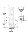
- a multisolid fluidized bed 1 is shown schematically.
- a fluidizing gas or primary air 2 enters the combustor at the bottom and passes through distributor plate 3.
- Fuel and possibly a sulfur sorbent enter at 4.
- the fuel is generally oil or particulate coal or coke.
- the sulfur sorbent is conventional and may for example be limestone, lime or dolomite.
- the sulfur sorbent could also enter at locations 8 or 9 with the secondary air to be later described.
- a coarse, particulate material is present in the combustor and is fluidized in the region I shown in the Figure.
- the size of the coarse component is generally in the range of -4+16 mesh (U.S. Standard) which is -4.76 mm+1.19 mm and preferably -6+12 U.S. mesh which is -3.36 mm+1.68 mm.
- the superficial gas velocity of the primary gas is generally in the range of about 10-60 feet per second (305-1830 cm/sec).
- the coarse component should be stable and inert under the operating conditions.
- Metal oxides are desirable materials for the dense bed. Iron oxide such as contained in hematite, is preferred though aluminium oxide, silica, or nickel oxide among others may be utilized.
- the primary air 2 also entrains a relatively fine particle component in the combustor regions I and II.
- the entrained fine particles are captured above the combustor by cyclone 11 and are recycled back to the combustor through recycle leg 7 and (in the present invention) also through recycle leg 6.
- Heat is removed from the entrained fines either by heat exchange tubing within region II in the combustor or preferably through heat exchange tubing in an external heat exchanger 12.
- a fluidizing gas 5 causes the fines to be retained in the external heat exchanger for a period of time sufficient to give up their heat.
- the fine particles can be made of the same materials as the coarse particles, but silica has been found to be particularly useful.
- the particle size of the fine particles is chosen to be successfully entrained at the superficial velocity of the primary air 2 but also to prevent backmixing into the dense bed when recycled through leg 6 in the Figure. As described later, a particle size of -40 U.S. mesh, which is 0.42 mm, is desirable and a range of -50+200 U.S. mesh, which is -0.30 mm+0.074 mm, is preferred with a coarse particle size of about -6+12 U.S. mesh, which is -3.36 mm+1.68 mm. Larger "fine” particles would backmix and finer "fines” may pass through the cyclones and not be recycled. However, larger fines could be used if larger coarse particles were used in the dense bed. The relative size is the important factor in preventing backmixing.
- the combustor described may be used to completely burn sulfur-bearing fuels in the dense bed region I and to capture sulfur dioxide with limestone in region II which is also known as the freeboard region.
- undesirable nitrogen oxides are formed in the dense bed during combustion and are emitted in the waste gas stream. It is known to limit the excess oxygen or to burn fuels under fuel rich or substoichiometric conditions in order to limit nitrogen oxide formation but several problems have resulted in prior methods utilizing this approach, not the least of which was a decrease in sulfur capture.
- the present invention proposes to reduce problems associated with co-removal of NO x and S0 2 from fuel combustion by creating two regions in a conventional multisolid fluidized combustor and operating the lower region in a fuel rich condition and the upper region in an oxidizing condition.
- the method further includes the recycle of at least a portion of the fine entrained bed particles into the upper oxidizing region for depressing the temperature therein. Backmixing of such recycled fines into the lower fuel-rich region may be prevented by maintaining a substantial size difference between the coarse dense bed particles and the fine entrained bed particles, thus eliminating the need for the orifice plate disclosed in our previous U.S.-A-4.,154,581.
- the orifice plate can be used however if a lesser size difference between coarse and fine fractions is found necessary for other reasons.
- the primary air ratio and the gas residence time are important variables.
- the primary air ratio as used herein means the ratio of the air introduced in the bottom of the combustor to fluidize the particles (total of the primary air 2 and any air used to inject fuel and other solids at 4 in the substoichiometric region) and the calculated stoichiometric air requirement for complete combustion of the fuel.
- the gas residence time as used herein shall mean the time interval for the gas to travel between a lower point and an upper point in the combustor. Mathematically, the gas residence time is equal to the distance between the two points divided by the superficial gas velocity.
- Oxidation in a conventional one-component bed may also be catastrophic in that unburned fuel (especially fines) and carbon monoxide from the fuel-rich zone will burn uncontrolled in the oxidizing zone thereby promoting wide temperature excursions.
- the high temperature can be both a threat to construction materials and an enemy of sulfur dioxide capture since any sulfates are decomposed back to sulfur dioxide at about 1900° F 1040°C).
- a lower region of the combustor marked "Reduction Region” is operated at substoichiometric conditions such that nitrogen oxides released during burning therein are reduced to gaseous nitrogen by char and carbon monoxide according to the following reactions:
- Secondary air is then injected at a preselected point, for example at 9, to bring the oxygen to the desired level (preferably about 10-50% excess air over stoichiometric) in the "Oxidation Region".
- Sulfur sorbent may also be injected at points 4, 8, 9 or 10 or may be recycled through recycle legs 6 and 7 to react with the sulfur and oxygen in the oxidation region to form disposable sulfate products.
- fine limestone is injected at 9 with the secondary air and reacts with sulfur to form gypsum.
- Combustion of unburned fuel also takes place in the upper oxidation region but temperature increases due to such combustion are depressed by recycling cool, fine particles from the entrained bed through cyclone 11, external heat exchanger 12 and recycle leg 6.
- the lower reduction region may be operated at as low a temperature as will support combustion, typically about 1450OF (790°C) for coal and about 1650 0 F (900°C) for coke. This allows the primary air ratio to be reduced to as low as about 0.35:
- the primary air ratio is controlled to about 0.4 to 0.6 (i.e. 40-60% of theoretical stoichiometric air).
- the upper oxidation region is preferably operated at a temperature of about 1600 ⁇ 1700°F (870 ⁇ 925°C) but at least below about 1900°F (1040°C) where CaS0 4 decomposes.
- the height of the reduction region is selected to allow sufficient residence time to reduce the NO x to the desired level.
- the reduction zone is chosen to be the same height (above the distributor plate 3) as the dense fluidized bed I.
- Both the upper recycle leg 6 for the entrained bed particles and the secondary air inlet 9 could be at the same level just above the dense bed as shown in the drawing Figure.
- the secondary air could actually be used to inject the recycle sand through leg 6 and thereby provide better distribution of the recycled particles across the combustor.
- the recycle leg 6 and/or the secondary air inlet 8 could be located just below the upper boundary of the dense bed I such that the better mixing therein is used to distribute the recycled particles. If necessary for better reduction of NO., the secondary air inlet could be located substantially above the dense bed such as at location 10.
- the air inlets at 8, 9 and 10 may be used one at a time or in concert to control the height of the reduction region.
- the height of the oxidation region is chosen to afford sufficient residence time for capture of S0 2 by the sorbent and the oxidation thereof.
- a balance must be struck between the height of the reduction and oxidation regions by the placement of the secondary air inlet.
- two or more secondary air inlets can be used, such as at locations 8, 9 and 10 in order to better control the temperature and oxidizing conditions over a larger region.
- the entrained bed particles continued to be recycled through the dense bed via recycle leg 7 from the external heat exchanger.
- the cooled particles are beneficially used to depress the temperature excursions in the oxidation region resulting from the burning of carbon monoxide and unburned fines coming from the reduction zone. Enough of the fine particles are recycled to maintain the temperature at a satisfactory level to protect construction materials and to promote sulfur dioxide capture and oxidation, preferably in the range of about 1600° ⁇ 1700°F (870 ⁇ 925°C).
- a multisolid fluidized bed combustor test unit was used to demonstrate the invention.
- the combustor column is made of Type 304 stainless steel pipe with a wall thickness of 1/8 inch (3.2 mm).
- the bottom section is 5 feet (1.5 m) in height (above the distributor plate) and has a 6 3/8 inch (16.2 cm) I.D. which is expanded to 8 1/4 inch (21 cm) I.D. for the remaining 15 feet (4.575) freeboard region of the combustor.
- a uniform diameter pipe has also been used but the expanded freeboard region provides longer gas retention time and better SO 2 capture. Thermal insulation around the combustor limits heat loss.
- Secondary air inlets enter the combustor chamber at vertical locations 27 inches (0.685 m), 48 inches (1.22 m), 70 inches (1.78 m), and 105 inches (2.6 m) above the distributor plate.
- the entrained bed particle recirculation system comprises a 12 inch (30.5 cm) diameter cyclone, an external heat exchanger and lower and upper solid recycle legs such as shown in the drawing Figure.
- the recycle legs enter the combustor chamber at vertical locations 2 inches (5 cm) and 48 inches (1.22 m) above the distributor.
- cyclones are installed in series for collecting fly ash.
- Fuel and the limestone sorbent are either premixed at a predetermined Ca/S ratio before feeding or are fed separately to the combustor at specified rates.
- a 1 inch (2.5 cm) diameter pneumatic injection line is used to introduce the fuel and limestone to the combustor at about 2 inches (5 cm) above the distributor plate.
- Petroleum coke having a higher heating value of 15,300 BTU/dry Ib (8500 Kcal/Kg) was used as the fuel. It contained less than 3% moisture and was screened to -8+50 U.S. mesh which is -2.38 mm+0.30 mm before use. Chemical analysis was as follows: Minus 325 Piqua limestone was used as sulfur sorbent. African iron ore (-6+16 U.S. mesh which is -3.36 mm+1.19 mm, 312 Ib/ft 3 (4.99 g/cm 3 ) density) and silica sand (-20+70 U.S. mesh which is -0.84 mm+0.21 mm, 162 Ib/ft 3 (2.59 g/cm 3 ) density) were used for the dense and entrained beds, respectively.
- the apparatus was similar to that described in Example 1.
- the fuel was petroleum coke and was fed at a rate of 36.9 pounds per hour (16.75 Kg/hr) into the combustor dense bed.
- the coarse particle dense bed was made up of African ore with a size of-6+12 U.S. mesh which is -3.36 mm+1.68 mm.
- the entrained bed was made up of -40 U.S. mesh which is 0.42 mm silica sand having a size distribution of:
- the fine entrained bed particles were cooled and recycled into the combustor through either upper recycle leg 6 or lower recycle leg 7 in the Figure.
- the upper recycle leg enters the combustor about 48 inches (1.22 m) above the distributor plate in the oxidation region.
- the combustion was staged by operating a lower region under substoichiometric conditions and then adding secondary air into the combustor above the dense bed to complete combustion and aid in sulfur capture efficiency.
- Primary air was used at 36.9 SCFM (17.4 I/sec) to fluidize the bed and secondary air was added as follows:
Landscapes
- Engineering & Computer Science (AREA)
- Chemical & Material Sciences (AREA)
- Combustion & Propulsion (AREA)
- Chemical Kinetics & Catalysis (AREA)
- Mechanical Engineering (AREA)
- General Engineering & Computer Science (AREA)
- Biomedical Technology (AREA)
- Health & Medical Sciences (AREA)
- Organic Chemistry (AREA)
- Environmental & Geological Engineering (AREA)
- Analytical Chemistry (AREA)
- General Chemical & Material Sciences (AREA)
- Oil, Petroleum & Natural Gas (AREA)
- Fluidized-Bed Combustion And Resonant Combustion (AREA)
- Treating Waste Gases (AREA)
- Catalysts (AREA)
- Traffic Control Systems (AREA)
- Transition And Organic Metals Composition Catalysts For Addition Polymerization (AREA)
- Radar Systems Or Details Thereof (AREA)
Abstract
Description
- Federal and state air quality standards on emissions have made it necessary to seek methods of cleaner burning for carbonaceous fuels. Both S02 and NOx are legislatively regulated. The differences in the behavior of these pollutants and the differences in the best available methods for independently eliminating these gases make an existing single-stage combustion process for their co-removal highly unlikely or at least inefficient.
- Fluidized bed combustion has developed recently for burning sulfur-bearing, carbonaceous fuels. This is primarily due to the ability to contact the sulfur dioxide reaction product with a sulfur sorbent for a period of time sufficient to capture a high percentage of the sulfur dioxide. Work on nitrogen oxide removal has trailed the work on sulfur oxide capture because of less stringent legislation to this point.
- It is an object of the present invention to provide a method for ridding combustion gases of nitrogen oxide pollutants.
- It is also an object of the invention to provide such method in a conventional multisolid fluidized bed combustor.
- It is further an object to minimize the sulfur dioxide emissions released during such inventive process.
- It is also an object to provide a simple method for optimizing nitrogen and sulfur oxide emissions from a multisolid fluidised bed combustor.
- In accordance with the above objectives, the invention provides a method of lowering nitrogen oxides to a desired level and minimising sulfur dioxide in the reaction gases from the combustion of fuel in a multisolid fluidised bed having a lower dense fluidised bed of relatively large particles, an upper dispersed entrained bed of relatively fine particles recirculating through the dense fluidised bed and an entrained sulfur sorbent material therein, which comprises:
- (a) operating a lower region of the multisolid fluidised bed under substoichiometric conditions such that NOx is reduced to the desired level,
- (b) operating an upper region of the multisolid fluidised bed above the substoichiometric lower region under oxidising conditions to complete the combustion of the fuel, characterised in that:
- (c) a size difference is maintained between the relatively large particles and the relatively fine particles such that substantially all of the former are at least about four times the size of substantially all of the latter, and
- (d) at least a portion of the cooled relatively fine particles is recycled from the entrained bed through substantially only the upper region which is operating under oxidising conditions whereby to depress the temperature of such oxidising region to a level conducive to sulfur capture by the sulfur sorbent material.
- The substoichiometric region is preferably limited to the dense fluidised bed or a substantial portion thereof.
- The region of reducing conditions is preferably maintained such that air is about 40-60% of stoichiometric requirements and the region of oxidizing conditions is preferably maintained at about 18% excess air.
- The temperature in such fluidized bed varies depending, among other things, on the specific fuel used, but is preferably maintained at a uniform level of about 1600-1700° (870-925°C) for most coals and about 1700-1750°F (925-950°C) for most cokes.
- Air for the reducing region is preferably provided by the primary fluidizing gas while oxidizing conditions are preferably provided by introducing secondary air at one or more locations between a point in the dense bed near the upper boundary thereof to a point in the dispersed, entrained bed several feet upwards from the dense bed. The position of the secondary air affects the relative effectiveness of nitrogen oxide reduction and sulfur capture; the higher the entrance of secondary air, the more favorable the nitrogen reduction relative to sulfur capture. The residence time of the gas in the two regions is a significant factor in the completeness of reaction therein.
- A portion of the cooled fine particles of the entrained bed are conventionally recycled through the dense bed in order to provide mixing therein. The remainder of the fine particles are recycled through the oxidizing region in order to depress the temperature therein. Backward mixing of the latter fine particles into the dense bed is prevented by maintaining a difference in the sizes of coarse dense bed particles and the fine, entrained bed particles, such that substantially all the particles in the dense bed be at least 4 times the size (diameter) of substantially all the particles in the entrained bed. Specific size ranges are (U.S. Standard sieve sizes (-4+16 which is a range of -4.76 mm+1.19 mm, (preferably -6+12 which is a range of -3.36 mm+1.68 mm) for the dense bed particles and -40 which is -0.42 mm (preferably -50+200 which is -0.30 mm+0.074 mm) for the entrained bed particles.
- Multisolid fluidized beds have demonstrated the ability to burn sulfur-bearing, carbonaceous fuel at low S02 pollution levels when a sulfur sorbent such as limestone is contacted with the reaction gases. The method of operating a multisolid fluidized bed is described in detail in our prior U.S.-A-4,084,545. We will not further describe the now conventional operation in great detail. The important features to be remembered are a dense, coarse-particle fluidized bed at the lower extreme of the apparatus and a larger entrained bed of finer particles overlapping and recirculating through the dense bed. The fluidizing gas enters at the bottom to fluidize the coarse particles and to entrain the fines. The overlapping dense and fine beds provide thorough mixing for more complete reaction than available in one-component fluidized beds.
- Our second U.S.-A-4,154,581 describes the operation of such multisolid fluidized beds with two different temperature zones by providing a baffling means in the dense bed and using the recirculation of entrained bed particles to affect the temperature at their point of entry into the dense bed above or below the baffling means. Somewhat larger fine particles were suggested in the latter patent over those preferred in the present inventive method.
- The present invention is a further improvement in the operation of multisolid fluidized beds of the type shown in the prior two mentioned patents. The improved operation allows the combustion of sulfur-bearing carbonaceous fuels while remaining substantially below legislated levels of both NOx and S02 emissions.
- The inventive method can be best understood by looking at the drawing Figure where a multisolid fluidized bed 1 is shown schematically. In conventional operation a fluidizing gas or
primary air 2 enters the combustor at the bottom and passes through distributor plate 3. Fuel and possibly a sulfur sorbent enter at 4. The fuel is generally oil or particulate coal or coke. The sulfur sorbent is conventional and may for example be limestone, lime or dolomite. The sulfur sorbent could also enter at locations 8 or 9 with the secondary air to be later described. - A coarse, particulate material is present in the combustor and is fluidized in the region I shown in the Figure. The size of the coarse component is generally in the range of -4+16 mesh (U.S. Standard) which is -4.76 mm+1.19 mm and preferably -6+12 U.S. mesh which is -3.36 mm+1.68 mm. As known in the art, a balance between the particle size and the velocity of the fluidizing gas is necessary to keep the bed fluidized in the region I. The superficial gas velocity of the primary gas is generally in the range of about 10-60 feet per second (305-1830 cm/sec). The coarse component should be stable and inert under the operating conditions. Metal oxides are desirable materials for the dense bed. Iron oxide such as contained in hematite, is preferred though aluminium oxide, silica, or nickel oxide among others may be utilized.
- The
primary air 2 also entrains a relatively fine particle component in the combustor regions I and II. The entrained fine particles are captured above the combustor by cyclone 11 and are recycled back to the combustor through recycle leg 7 and (in the present invention) also throughrecycle leg 6. Heat is removed from the entrained fines either by heat exchange tubing within region II in the combustor or preferably through heat exchange tubing in anexternal heat exchanger 12. A fluidizinggas 5 causes the fines to be retained in the external heat exchanger for a period of time sufficient to give up their heat. - The fine particles can be made of the same materials as the coarse particles, but silica has been found to be particularly useful. The particle size of the fine particles is chosen to be successfully entrained at the superficial velocity of the
primary air 2 but also to prevent backmixing into the dense bed when recycled throughleg 6 in the Figure. As described later, a particle size of -40 U.S. mesh, which is 0.42 mm, is desirable and a range of -50+200 U.S. mesh, which is -0.30 mm+0.074 mm, is preferred with a coarse particle size of about -6+12 U.S. mesh, which is -3.36 mm+1.68 mm. Larger "fine" particles would backmix and finer "fines" may pass through the cyclones and not be recycled. However, larger fines could be used if larger coarse particles were used in the dense bed. The relative size is the important factor in preventing backmixing. - In normal operation the combustor described may be used to completely burn sulfur-bearing fuels in the dense bed region I and to capture sulfur dioxide with limestone in region II which is also known as the freeboard region. However, in this operation undesirable nitrogen oxides are formed in the dense bed during combustion and are emitted in the waste gas stream. It is known to limit the excess oxygen or to burn fuels under fuel rich or substoichiometric conditions in order to limit nitrogen oxide formation but several problems have resulted in prior methods utilizing this approach, not the least of which was a decrease in sulfur capture.
- The present invention proposes to reduce problems associated with co-removal of NOx and S02 from fuel combustion by creating two regions in a conventional multisolid fluidized combustor and operating the lower region in a fuel rich condition and the upper region in an oxidizing condition. The method further includes the recycle of at least a portion of the fine entrained bed particles into the upper oxidizing region for depressing the temperature therein. Backmixing of such recycled fines into the lower fuel-rich region may be prevented by maintaining a substantial size difference between the coarse dense bed particles and the fine entrained bed particles, thus eliminating the need for the orifice plate disclosed in our previous U.S.-A-4.,154,581. The orifice plate can be used however if a lesser size difference between coarse and fine fractions is found necessary for other reasons.
- In carrying out the invention the primary air ratio and the gas residence time are important variables. The primary air ratio as used herein means the ratio of the air introduced in the bottom of the combustor to fluidize the particles (total of the
primary air 2 and any air used to inject fuel and other solids at 4 in the substoichiometric region) and the calculated stoichiometric air requirement for complete combustion of the fuel. The gas residence time as used herein shall mean the time interval for the gas to travel between a lower point and an upper point in the combustor. Mathematically, the gas residence time is equal to the distance between the two points divided by the superficial gas velocity. - If the only objective was to reduce NOx during combustion, it would be desirable to operate in a highly substoichiometric mode. But in normal, one-component fluid beds this would lead to several problems. One problem is the reaction of the sulfur sorbent, for example limestone, with the sulfur, yielding CaS. Under fuel-rich conditions this product would be drained from the fluidized bed as solid waste. Unfortunately, CaS is an environmentally undesirable waste and is particularly unsuitable for landfill disposal. Moreover, oxidation of the CaS before its exit from the fluidized bed is unsatisfactory due to short retention time and poor mixing.
- Oxidation in a conventional one-component bed may also be catastrophic in that unburned fuel (especially fines) and carbon monoxide from the fuel-rich zone will burn uncontrolled in the oxidizing zone thereby promoting wide temperature excursions. The high temperature can be both a threat to construction materials and an enemy of sulfur dioxide capture since any sulfates are decomposed back to sulfur dioxide at about 1900° F 1040°C).
- The present invention therefore minimizes these problems in the following manner. Referring again to the drawing Figure, a lower region of the combustor marked "Reduction Region" is operated at substoichiometric conditions such that nitrogen oxides released during burning therein are reduced to gaseous nitrogen by char and carbon monoxide according to the following reactions:


points 4, 8, 9 or 10 or may be recycled through recyclelegs 6 and 7 to react with the sulfur and oxygen in the oxidation region to form disposable sulfate products. For example, fine limestone is injected at 9 with the secondary air and reacts with sulfur to form gypsum. - Combustion of unburned fuel also takes place in the upper oxidation region but temperature increases due to such combustion are depressed by recycling cool, fine particles from the entrained bed through cyclone 11,
external heat exchanger 12 and recycleleg 6. - The lower reduction region may be operated at as low a temperature as will support combustion, typically about 1450OF (790°C) for coal and about 16500F (900°C) for coke. This allows the primary air ratio to be reduced to as low as about 0.35: The lower the primary air ratio the lower is the emission level of NOx. Preferably, the primary air ratio is controlled to about 0.4 to 0.6 (i.e. 40-60% of theoretical stoichiometric air). The upper oxidation region is preferably operated at a temperature of about 1600―1700°F (870―925°C) but at least below about 1900°F (1040°C) where CaS04 decomposes.
- The height of the reduction region is selected to allow sufficient residence time to reduce the NOx to the desired level. The higher the reduction zone, the longer the residence time and the less NOx will escape without reacting with char and carbon monoxide. Generally, the reduction zone is chosen to be the same height (above the distributor plate 3) as the dense fluidized bed I. Both the
upper recycle leg 6 for the entrained bed particles and the secondary air inlet 9 could be at the same level just above the dense bed as shown in the drawing Figure. Likewise, the secondary air could actually be used to inject the recycle sand throughleg 6 and thereby provide better distribution of the recycled particles across the combustor. - In the alternative, the
recycle leg 6 and/or the secondary air inlet 8 could be located just below the upper boundary of the dense bed I such that the better mixing therein is used to distribute the recycled particles. If necessary for better reduction of NO., the secondary air inlet could be located substantially above the dense bed such as at location 10. The air inlets at 8, 9 and 10 may be used one at a time or in concert to control the height of the reduction region. - The height of the oxidation region is chosen to afford sufficient residence time for capture of S02 by the sorbent and the oxidation thereof. Clearly with a finite height of the combustor, a balance must be struck between the height of the reduction and oxidation regions by the placement of the secondary air inlet. Moreover, two or more secondary air inlets can be used, such as at locations 8, 9 and 10 in order to better control the temperature and oxidizing conditions over a larger region.
- Some of the entrained bed particles continued to be recycled through the dense bed via recycle leg 7 from the external heat exchanger. However, as earlier stated, the cooled particles are beneficially used to depress the temperature excursions in the oxidation region resulting from the burning of carbon monoxide and unburned fines coming from the reduction zone. Enough of the fine particles are recycled to maintain the temperature at a satisfactory level to protect construction materials and to promote sulfur dioxide capture and oxidation, preferably in the range of about 1600°―1700°F (870―925°C).
- A multisolid fluidized bed combustor test unit was used to demonstrate the invention. The combustor column is made of Type 304 stainless steel pipe with a wall thickness of 1/8 inch (3.2 mm). The bottom section is 5 feet (1.5 m) in height (above the distributor plate) and has a 6 3/8 inch (16.2 cm) I.D. which is expanded to 8 1/4 inch (21 cm) I.D. for the remaining 15 feet (4.575) freeboard region of the combustor. A uniform diameter pipe has also been used but the expanded freeboard region provides longer gas retention time and better SO2 capture. Thermal insulation around the combustor limits heat loss.
- Secondary air inlets enter the combustor chamber at vertical locations 27 inches (0.685 m), 48 inches (1.22 m), 70 inches (1.78 m), and 105 inches (2.6 m) above the distributor plate. The entrained bed particle recirculation system comprises a 12 inch (30.5 cm) diameter cyclone, an external heat exchanger and lower and upper solid recycle legs such as shown in the drawing Figure. The recycle legs enter the combustor chamber at
vertical locations 2 inches (5 cm) and 48 inches (1.22 m) above the distributor. - Other cyclones are installed in series for collecting fly ash. Fuel and the limestone sorbent are either premixed at a predetermined Ca/S ratio before feeding or are fed separately to the combustor at specified rates. A 1 inch (2.5 cm) diameter pneumatic injection line is used to introduce the fuel and limestone to the combustor at about 2 inches (5 cm) above the distributor plate.
- Petroleum coke having a higher heating value of 15,300 BTU/dry Ib (8500 Kcal/Kg) was used as the fuel. It contained less than 3% moisture and was screened to -8+50 U.S. mesh which is -2.38 mm+0.30 mm before use. Chemical analysis was as follows:

- Operating conditions were as follows:

- Cool entrained bed particles were not recycled through the upper oxidizing region in this trial. Coke particles which have a low once through combustion efficiency were recycled through the lower recycle leg with fine entrained bed particles in order to obtain total combustion efficiencies of greater than about 93%. Results of sulfur dioxide and nitrogen oxide emissions for several runs are given in Tables 1 and 2.


- It is seen that the sulfur dioxide emissions increased somewhat under staged combustion but that nitrogen oxide emissions could be reduced from about 325 ppm down to less than 50 ppm by operating the lower region at substoichiometric conditions and increasing the gas residence time therein by decreasing superficial velocity. The secondary air was injected in all cases at the either 70 or 105 inch (1.78 or 2.6 m) level.
- The effects of varying the location of the secondary air injection and hence the relative height of and residence time in the reducing and oxidizing regions can be seen in Table 3.

- It is clear that the relative amounts of sulfur dioxide and nitrogen oxide emissions are directly affected by the height of the reducing and oxidizing regions. It is clear also from Table 1-3 that both nitrogen oxide and sulfur dioxide emissions can be reduced by this staged combustion and by increasing the residence time in the reducing and oxidizing regions either through lower superficial velocities or lengthened combustor dimensions.
- Apparatus such as described in Example 1 was used except that the combustor was a
uniform 6 3/8 inch (16.2 cm) I.D. pipe and the cycxlone and external heat exchanger were replaced with a 14 inch (35.6 cm) cyclone. Secondary air inlets were located at 28 inches (71 cm), 44 inches (1.1 m) and 202 inches (5.2 m) above the distributor plate.Illinois # 6 coal (-6 U.S. mesh which is -3.36 mm) analyzing 4% sulfur and 1.2% nitrogen was used as the fuel and -325 U.S. mesh which is -0.044 mm Piqua limestone remained the sorbent. The results of several runs which are shown in Table 4 demonstrate the balance which can be used in injecting secondary air to optimize the emissions of nitrogen and sulfur. Excessive burning in the oxidation region together with high temperature excursions were noted during these runs.
- Excessive burning of carbon monoxide and. unburned coke fines in the freeboard or oxidation region may cause elevated temperatures and potential damage to materials as well as reduced efficiency in the sulfur dioxide capture by the sorbent. In order to depress the temperature excursions in this example, cool entrained bed particles were recycled directly into the oxidation region.
- The apparatus was similar to that described in Example 1. The fuel was petroleum coke and was fed at a rate of 36.9 pounds per hour (16.75 Kg/hr) into the combustor dense bed.
- The coarse particle dense bed was made up of African ore with a size of-6+12 U.S. mesh which is -3.36 mm+1.68 mm. The entrained bed was made up of -40 U.S. mesh which is 0.42 mm silica sand having a size distribution of:

upper recycle leg 6 or lower recycle leg 7 in the Figure. The upper recycle leg enters the combustor about 48 inches (1.22 m) above the distributor plate in the oxidation region. - The combustion was staged by operating a lower region under substoichiometric conditions and then adding secondary air into the combustor above the dense bed to complete combustion and aid in sulfur capture efficiency. Primary air was used at 36.9 SCFM (17.4 I/sec) to fluidize the bed and secondary air was added as follows:

- Under the above conditions the fuel was burned and heat withdrawn in the external heat exchanger. Temperatures of the dense bed (16 inches [40.6 cm] above the distributor plate) and of the oxidation region (232 inches [5.88 m] above the distributor plate) were measured while varying the relative amount of cool fine particles recycled into the dense (reducing) bed and the freeboard (oxidation region). The results are shown in Table 5 and show that the dense bed can be maintained at a constant

Claims (10)
Priority Applications (1)
| Application Number | Priority Date | Filing Date | Title |
|---|---|---|---|
| AT80304736T ATE12188T1 (en) | 1979-12-26 | 1980-12-29 | REDUCTION OF NOX IN FLUID BED COMBUSTION FURNACES. |
Applications Claiming Priority (2)
| Application Number | Priority Date | Filing Date | Title |
|---|---|---|---|
| US06/106,745 US4704084A (en) | 1979-12-26 | 1979-12-26 | NOX reduction in multisolid fluidized bed combustors |
| US106745 | 1987-10-08 |
Publications (2)
| Publication Number | Publication Date |
|---|---|
| EP0033808A1 EP0033808A1 (en) | 1981-08-19 |
| EP0033808B1 true EP0033808B1 (en) | 1985-03-20 |
Family
ID=22313021
Family Applications (2)
| Application Number | Title | Priority Date | Filing Date |
|---|---|---|---|
| EP81900256A Withdrawn EP0042418A1 (en) | 1979-12-26 | 1980-12-22 | NOx REDUCTION IN MULTISOLID FLUIDIZED BED COMBUSTORS |
| EP80304736A Expired EP0033808B1 (en) | 1979-12-26 | 1980-12-29 | Nox reduction in multisolid fluidized bed combustors |
Family Applications Before (1)
| Application Number | Title | Priority Date | Filing Date |
|---|---|---|---|
| EP81900256A Withdrawn EP0042418A1 (en) | 1979-12-26 | 1980-12-22 | NOx REDUCTION IN MULTISOLID FLUIDIZED BED COMBUSTORS |
Country Status (12)
| Country | Link |
|---|---|
| US (1) | US4704084A (en) |
| EP (2) | EP0042418A1 (en) |
| JP (1) | JPS56501811A (en) |
| AT (1) | ATE12188T1 (en) |
| BR (1) | BR8009003A (en) |
| CA (1) | CA1156516A (en) |
| DE (1) | DE3070358D1 (en) |
| DK (1) | DK150285C (en) |
| FI (1) | FI69694C (en) |
| NO (1) | NO153746C (en) |
| WO (1) | WO1981001873A1 (en) |
| ZA (1) | ZA808096B (en) |
Families Citing this family (53)
| Publication number | Priority date | Publication date | Assignee | Title |
|---|---|---|---|---|
| CA1184743A (en) * | 1981-10-09 | 1985-04-02 | Herbert A. Arbib | Superjet gas agitation process |
| US4453497A (en) * | 1982-12-21 | 1984-06-12 | Struthers Wells Corporation | Augmented heat transfer method and apparatus |
| US5171542A (en) * | 1984-03-20 | 1992-12-15 | A. Ahlstrom Corporation | Circulating fluidized bed reactor |
| US4672918A (en) * | 1984-05-25 | 1987-06-16 | A. Ahlstrom Corporation | Circulating fluidized bed reactor temperature control |
| FI79403C (en) * | 1984-06-01 | 1989-12-11 | Ahlstroem Oy | Combustion method. |
| US4579070A (en) * | 1985-03-01 | 1986-04-01 | The M. W. Kellogg Company | Reducing mode circulating fluid bed combustion |
| DK158531C (en) * | 1985-06-13 | 1990-10-29 | Aalborg Vaerft As | PROCEDURE FOR CONTINUOUS OPERATION OF A CIRCULATING FLUIDIZED BED REACTOR AND REACTOR TO USE IN EXERCISE OF THE PROCEDURE |
| FI853615A7 (en) * | 1985-09-20 | 1987-03-21 | Tampella Oy Ab | Method for reducing nitrogen and sulfur dioxide emissions when burning nitrogen and sulfur-rich fuel. |
| FI86105C (en) * | 1985-11-19 | 1992-07-10 | Ahlstroem Oy | FOERFARANDE OCH ANORDNING FOER REGLERING AV EN VIRVELBAEDDSREAKTORS FUNKTION. |
| EP0311599B1 (en) * | 1985-12-09 | 1990-11-07 | A. Ahlstrom Corporation | A circulating fluidized bed reactor and a method of separating solid material from the flue gases |
| NO159879C (en) * | 1986-05-02 | 1989-02-15 | Santo As | PROCEDURES FOR OPERATION OF A COMBUSTION PLANT, SEAT FOR IMPLEMENTATION. |
| US4643110A (en) * | 1986-07-07 | 1987-02-17 | Enron, Inc. | Direct fuel-fired furnace arrangement for the recovery of gallium and germanium from coal fly ash |
| DE3702089C1 (en) * | 1987-01-24 | 1988-06-30 | Kernforschungsanlage Juelich | Fluid bed furnace for waste incineration |
| DE3702892A1 (en) * | 1987-01-31 | 1988-08-11 | Rheinische Braunkohlenw Ag | METHOD AND DEVICE FOR TREATING GRAINY SOLIDS IN A FLUID BED |
| US4869207A (en) * | 1987-07-13 | 1989-09-26 | A. Ahlstrom Corporation | Circulating fluidized bed reactor |
| FR2620517B1 (en) * | 1987-09-14 | 1989-12-22 | Fives Cail Babcock | FLUIDIZED BED COMBUSTION PROCESS AND INSTALLATION FOR CARRYING OUT SAID METHOD |
| US5141708A (en) * | 1987-12-21 | 1992-08-25 | Foster Wheeler Energy Corporation | Fluidized bed combustion system and method having an integrated recycle heat exchanger |
| FI87013C (en) * | 1988-01-04 | 1992-11-10 | Tampella Oy Ab | Burning process for reducing formation of nitrogen oxides in connection with combustion and apparatus for applying the process |
| JP2637449B2 (en) * | 1988-01-12 | 1997-08-06 | 三菱重工業株式会社 | Fluidized bed combustion method |
| US4881476A (en) * | 1988-07-26 | 1989-11-21 | The United States Of America As Represented By The United States Department Of Energy | Cyclone reactor with internal separation and axial recirculation |
| US4927348A (en) * | 1988-11-14 | 1990-05-22 | Mobil Oil Corporation | Circulating fluid bed combustion with CO combustion promoter and reduced combustion air |
| WO1991012464A1 (en) * | 1988-11-14 | 1991-08-22 | Mobil Oil Corporation | Circulating fluid bed combustion with circulating co combustion promoter |
| WO1991012465A1 (en) * | 1988-11-14 | 1991-08-22 | Mobil Oil Corporation | Circulating fluid bed combustion with co combustion promoter |
| US4899695A (en) * | 1989-02-14 | 1990-02-13 | Air Products And Chemicals, Inc. | Fluidized bed combustion heat transfer enhancement |
| US5069170A (en) * | 1990-03-01 | 1991-12-03 | Foster Wheeler Energy Corporation | Fluidized bed combustion system and method having an integral recycle heat exchanger with inlet and outlet chambers |
| US5133943A (en) * | 1990-03-28 | 1992-07-28 | Foster Wheeler Energy Corporation | Fluidized bed combustion system and method having a multicompartment external recycle heat exchanger |
| US5069171A (en) * | 1990-06-12 | 1991-12-03 | Foster Wheeler Agency Corporation | Fluidized bed combustion system and method having an integral recycle heat exchanger with a transverse outlet chamber |
| US5054436A (en) * | 1990-06-12 | 1991-10-08 | Foster Wheeler Energy Corporation | Fluidized bed combustion system and process for operating same |
| FR2669099B1 (en) * | 1990-11-13 | 1994-03-18 | Stein Industrie | METHOD AND DEVICE FOR COMBUSTING DIVIDED CARBON MATERIALS. |
| US5040492A (en) * | 1991-01-14 | 1991-08-20 | Foster Wheeler Energy Corporation | Fluidized bed combustion system and method having a recycle heat exchanger with a non-mechanical solids control system |
| US5140950A (en) * | 1991-05-15 | 1992-08-25 | Foster Wheeler Energy Corporation | Fluidized bed combustion system and method having an integral recycle heat exchanger with recycle rate control and backflow sealing |
| US5163374A (en) * | 1991-08-27 | 1992-11-17 | Institute Of Gas Technology | Combustion process |
| FI91800C (en) * | 1991-09-12 | 1994-08-10 | Imatran Voima Oy | Method and apparatus for cooling the circulating mass of a fluidized bed boiler |
| AU1449992A (en) * | 1992-03-05 | 1993-10-05 | Technische Universiteit Delft | Method and apparatus for combusting a carbonaceous material |
| US5325796A (en) * | 1992-05-22 | 1994-07-05 | Foster Wheeler Energy Corporation | Process for decreasing N2 O emissions from a fluidized bed reactor |
| US5239946A (en) * | 1992-06-08 | 1993-08-31 | Foster Wheeler Energy Corporation | Fluidized bed reactor system and method having a heat exchanger |
| US5390612A (en) * | 1993-03-01 | 1995-02-21 | Foster Wheeler Energy Corporation | Fluidized bed reactor having a furnace strip-air system and method for reducing heat content and increasing combustion efficiency of drained furnace solids |
| ZA946850B (en) * | 1993-09-13 | 1995-04-21 | Dorr Oliver Inc | Firing liquid and gaseous fuels for a circulating fluidized bed reactor |
| US5735682A (en) * | 1994-08-11 | 1998-04-07 | Foster Wheeler Energy Corporation | Fluidized bed combustion system having an improved loop seal valve |
| US5463968A (en) * | 1994-08-25 | 1995-11-07 | Foster Wheeler Energy Corporation | Fluidized bed combustion system and method having a multicompartment variable duty recycle heat exchanger |
| US6418866B1 (en) * | 1998-06-16 | 2002-07-16 | Mitsubishi Heavy Industries, Ltd. | Operating method of fluidized-bed incinerator and the incinerator |
| US6089855A (en) * | 1998-07-10 | 2000-07-18 | Thermo Power Corporation | Low NOx multistage combustor |
| DE10051733B4 (en) * | 2000-10-18 | 2005-08-04 | Fraunhofer-Gesellschaft zur Förderung der angewandten Forschung e.V. | Process for the gradual combustion of fuels |
| US8449288B2 (en) * | 2003-03-19 | 2013-05-28 | Nalco Mobotec, Inc. | Urea-based mixing process for increasing combustion efficiency and reduction of nitrogen oxides (NOx) |
| US7670569B2 (en) * | 2003-06-13 | 2010-03-02 | Mobotec Usa, Inc. | Combustion furnace humidification devices, systems & methods |
| US7537743B2 (en) * | 2004-02-14 | 2009-05-26 | Mobotec Usa, Inc. | Method for in-furnace regulation of SO3 in catalytic NOx reducing systems |
| US8251694B2 (en) * | 2004-02-14 | 2012-08-28 | Nalco Mobotec, Inc. | Method for in-furnace reduction flue gas acidity |
| US7410356B2 (en) * | 2005-11-17 | 2008-08-12 | Mobotec Usa, Inc. | Circulating fluidized bed boiler having improved reactant utilization |
| CN100491824C (en) * | 2007-11-02 | 2009-05-27 | 清华大学 | Low bed pressure-reducing circulated fluid bed boiler combustion process |
| US8069824B2 (en) | 2008-06-19 | 2011-12-06 | Nalco Mobotec, Inc. | Circulating fluidized bed boiler and method of operation |
| FI123853B (en) * | 2009-03-06 | 2013-11-15 | Metso Power Oy | Procedure for reducing nitric oxide emissions during oxygen combustion |
| FI125496B (en) | 2009-08-17 | 2015-10-30 | Valmet Technologies Oy | Method and arrangement for optimizing the combustion conditions in a fluidized bed boiler |
| CN112426877B (en) * | 2020-09-24 | 2022-07-19 | 宣城市楷昂化工有限公司 | Method and equipment for treating nitrogen oxide waste gas in sodium metabisulfite production |
Citations (6)
| Publication number | Priority date | Publication date | Assignee | Title |
|---|---|---|---|---|
| DE1181682B (en) * | 1957-08-28 | 1964-11-19 | Reinluft G M B H | Process for the production of activated carbon |
| US4033725A (en) * | 1972-02-24 | 1977-07-05 | John Zink Company | Apparatus for NOx control using steam-hydrocarbon injection |
| GB1488087A (en) * | 1975-03-04 | 1977-10-05 | Zink Co John | Process for disposal of oxides of nitrogen |
| US4084545A (en) * | 1975-10-21 | 1978-04-18 | Battelle Development Corporation | Operating method |
| US4154581A (en) * | 1978-01-12 | 1979-05-15 | Battelle Development Corporation | Two-zone fluid bed combustion or gasification process |
| DE2911712A1 (en) * | 1979-03-24 | 1980-09-25 | Bergwerksverband Gmbh | METHOD FOR REMOVING SULFUR OXIDS AND NITROGEN OXIDS FROM EXHAUST GASES |
Family Cites Families (6)
| Publication number | Priority date | Publication date | Assignee | Title |
|---|---|---|---|---|
| DE2452717A1 (en) * | 1974-11-06 | 1976-05-13 | Nissan Motor | Catalytic engine exhaust gas treatment - with second oxidation catalyst before reduction catalyst and secondary air admission after it |
| US4017272A (en) * | 1975-06-05 | 1977-04-12 | Bamag Verfahrenstechnik Gmbh | Process for gasifying solid carbonaceous fuel |
| US4021184A (en) * | 1975-10-02 | 1977-05-03 | Dorr-Oliver Incorporated | Dilute phase waste incinerator |
| DE2624302C2 (en) * | 1976-05-31 | 1987-04-23 | Metallgesellschaft Ag, 6000 Frankfurt | Methods for carrying out exothermic processes |
| US4103646A (en) * | 1977-03-07 | 1978-08-01 | Electric Power Research Institute, Inc. | Apparatus and method for combusting carbonaceous fuels employing in tandem a fast bed boiler and a slow boiler |
| US4158701A (en) * | 1978-11-06 | 1979-06-19 | Kaiser Aluminum & Chemical Corporation | Pyrohydrolysis system for processing fluorine-containing spent and waste materials |
-
1979
- 1979-12-26 US US06/106,745 patent/US4704084A/en not_active Expired - Lifetime
-
1980
- 1980-12-22 WO PCT/US1980/001737 patent/WO1981001873A1/en not_active Ceased
- 1980-12-22 JP JP81500438A patent/JPS56501811A/ja active Pending
- 1980-12-22 EP EP81900256A patent/EP0042418A1/en not_active Withdrawn
- 1980-12-22 BR BR8009003A patent/BR8009003A/en unknown
- 1980-12-29 DE DE8080304736T patent/DE3070358D1/en not_active Expired
- 1980-12-29 EP EP80304736A patent/EP0033808B1/en not_active Expired
- 1980-12-29 CA CA000367656A patent/CA1156516A/en not_active Expired
- 1980-12-29 AT AT80304736T patent/ATE12188T1/en not_active IP Right Cessation
- 1980-12-29 ZA ZA00808096A patent/ZA808096B/en unknown
-
1981
- 1981-08-25 DK DK375981A patent/DK150285C/en active
- 1981-08-25 NO NO812872A patent/NO153746C/en unknown
- 1981-08-26 FI FI812631A patent/FI69694C/en not_active IP Right Cessation
Patent Citations (6)
| Publication number | Priority date | Publication date | Assignee | Title |
|---|---|---|---|---|
| DE1181682B (en) * | 1957-08-28 | 1964-11-19 | Reinluft G M B H | Process for the production of activated carbon |
| US4033725A (en) * | 1972-02-24 | 1977-07-05 | John Zink Company | Apparatus for NOx control using steam-hydrocarbon injection |
| GB1488087A (en) * | 1975-03-04 | 1977-10-05 | Zink Co John | Process for disposal of oxides of nitrogen |
| US4084545A (en) * | 1975-10-21 | 1978-04-18 | Battelle Development Corporation | Operating method |
| US4154581A (en) * | 1978-01-12 | 1979-05-15 | Battelle Development Corporation | Two-zone fluid bed combustion or gasification process |
| DE2911712A1 (en) * | 1979-03-24 | 1980-09-25 | Bergwerksverband Gmbh | METHOD FOR REMOVING SULFUR OXIDS AND NITROGEN OXIDS FROM EXHAUST GASES |
Also Published As
| Publication number | Publication date |
|---|---|
| FI812631L (en) | 1981-08-26 |
| JPS56501811A (en) | 1981-12-10 |
| WO1981001873A1 (en) | 1981-07-09 |
| FI69694B (en) | 1985-11-29 |
| BR8009003A (en) | 1981-10-20 |
| EP0042418A1 (en) | 1981-12-30 |
| DK150285B (en) | 1987-01-26 |
| CA1156516A (en) | 1983-11-08 |
| DK375981A (en) | 1981-08-25 |
| NO153746C (en) | 1986-05-21 |
| ATE12188T1 (en) | 1985-04-15 |
| DE3070358D1 (en) | 1985-04-25 |
| EP0033808A1 (en) | 1981-08-19 |
| ZA808096B (en) | 1982-01-27 |
| DK150285C (en) | 1987-10-26 |
| NO812872L (en) | 1981-08-25 |
| FI69694C (en) | 1986-03-10 |
| US4704084A (en) | 1987-11-03 |
| NO153746B (en) | 1986-02-03 |
Similar Documents
| Publication | Publication Date | Title |
|---|---|---|
| US4704084A (en) | NOX reduction in multisolid fluidized bed combustors | |
| US5399194A (en) | Method of fly ash beneficiation and apparatus for same | |
| US4969930A (en) | Process for gasifying or combusting solid carbonaceous material | |
| US4154581A (en) | Two-zone fluid bed combustion or gasification process | |
| US4084545A (en) | Operating method | |
| CA1257809A (en) | Combustion method | |
| US4981111A (en) | Circulating fluidized bed combustion reactor with fly ash recycle | |
| US4955295A (en) | Method and system for controlling the backflow sealing efficiency and recycle rate in fluidized bed reactors | |
| US5715764A (en) | Combustion method | |
| US3508506A (en) | Process and apparatus for reduction of unburned combustible in fly ash | |
| PL168255B1 (en) | Method of burning nitrogen-containing fuels in a fluidized bed reactor PL PL PL PL PL | |
| CA1252338A (en) | Method for improving the operation of a fluidized bed | |
| US4308810A (en) | Apparatus and method for reduction of NOx emissions from a fluid bed combustion system through staged combustion | |
| JP2652323B2 (en) | Apparatus and method for two-stage combustion in a fluidized bed reactor | |
| US4475884A (en) | Reversed flow fluidized-bed combustion apparatus | |
| EP0652800B1 (en) | Reducing n2o emissions | |
| FURUSAWA et al. | Abatement of nitric oxide emission in fluidized bed combustion of coal | |
| US4056069A (en) | Method of burning refuse | |
| EP0824649B1 (en) | NOx reduction in a circulating fluidized bed | |
| AU6704581A (en) | No x reduction in multisolid fluidized bed combustors | |
| EP0156784B1 (en) | A method of reducing sulphur-oxide and nitrogen-oxide emission when burning solid fuel on travelling grates | |
| JP3132870B2 (en) | Gasification combustion method | |
| Kerr et al. | Fluidised bed combustion: Improved system design leading to reduced pollutant emissions | |
| KR100433252B1 (en) | Iron ore sintering method having coke concentration gradient | |
| GB2104796A (en) | Reduction of NOx emission from fluidized bed combustion systems |
Legal Events
| Date | Code | Title | Description |
|---|---|---|---|
| PUAI | Public reference made under article 153(3) epc to a published international application that has entered the european phase |
Free format text: ORIGINAL CODE: 0009012 |
|
| AK | Designated contracting states |
Designated state(s): AT BE CH DE FR GB IT LU NL SE |
|
| 17P | Request for examination filed |
Effective date: 19820115 |
|
| ITF | It: translation for a ep patent filed | ||
| GRAA | (expected) grant |
Free format text: ORIGINAL CODE: 0009210 |
|
| AK | Designated contracting states |
Designated state(s): AT BE CH DE FR GB IT LI LU NL SE |
|
| REF | Corresponds to: |
Ref document number: 12188 Country of ref document: AT Date of ref document: 19850415 Kind code of ref document: T |
|
| REF | Corresponds to: |
Ref document number: 3070358 Country of ref document: DE Date of ref document: 19850425 |
|
| ET | Fr: translation filed | ||
| PLBI | Opposition filed |
Free format text: ORIGINAL CODE: 0009260 |
|
| 26 | Opposition filed |
Opponent name: EVT ENERGIE UND VERFAHRENSTECHNIK GMBH Effective date: 19850912 |
|
| PG25 | Lapsed in a contracting state [announced via postgrant information from national office to epo] |
Ref country code: LU Free format text: LAPSE BECAUSE OF NON-PAYMENT OF DUE FEES Effective date: 19851231 |
|
| NLR1 | Nl: opposition has been filed with the epo |
Opponent name: EVT ENERGIE UND VERFAHRENSTECHNIK GMBH |
|
| PGFP | Annual fee paid to national office [announced via postgrant information from national office to epo] |
Ref country code: DE Payment date: 19890426 Year of fee payment: 9 |
|
| PGFP | Annual fee paid to national office [announced via postgrant information from national office to epo] |
Ref country code: CH Payment date: 19891101 Year of fee payment: 10 |
|
| PGFP | Annual fee paid to national office [announced via postgrant information from national office to epo] |
Ref country code: LU Payment date: 19891123 Year of fee payment: 10 |
|
| PGFP | Annual fee paid to national office [announced via postgrant information from national office to epo] |
Ref country code: SE Payment date: 19891218 Year of fee payment: 10 |
|
| PGFP | Annual fee paid to national office [announced via postgrant information from national office to epo] |
Ref country code: FR Payment date: 19891228 Year of fee payment: 10 |
|
| PGFP | Annual fee paid to national office [announced via postgrant information from national office to epo] |
Ref country code: BE Payment date: 19891229 Year of fee payment: 10 |
|
| ITTA | It: last paid annual fee | ||
| PGFP | Annual fee paid to national office [announced via postgrant information from national office to epo] |
Ref country code: NL Payment date: 19891231 Year of fee payment: 10 Ref country code: GB Payment date: 19891231 Year of fee payment: 10 Ref country code: AT Payment date: 19891231 Year of fee payment: 10 |
|
| RDAG | Patent revoked |
Free format text: ORIGINAL CODE: 0009271 |
|
| STAA | Information on the status of an ep patent application or granted ep patent |
Free format text: STATUS: PATENT REVOKED |
|
| 27W | Patent revoked |
Effective date: 19900113 |
|
| GBPR | Gb: patent revoked under art. 102 of the ep convention designating the uk as contracting state | ||
| REG | Reference to a national code |
Ref country code: CH Ref legal event code: PL |
|
| NLR2 | Nl: decision of opposition | ||
| BERE | Be: lapsed |
Owner name: BATTELLE DEVELOPMENT CORP. Effective date: 19901231 |
|
| EUG | Se: european patent has lapsed |
Ref document number: 80304736.4 Effective date: 19900314 |
|
| APAH | Appeal reference modified |
Free format text: ORIGINAL CODE: EPIDOSCREFNO |