EP0033638B1 - Producing compression molded fibre reinforced plastics panel - Google Patents
Producing compression molded fibre reinforced plastics panel Download PDFInfo
- Publication number
- EP0033638B1 EP0033638B1 EP81300385A EP81300385A EP0033638B1 EP 0033638 B1 EP0033638 B1 EP 0033638B1 EP 81300385 A EP81300385 A EP 81300385A EP 81300385 A EP81300385 A EP 81300385A EP 0033638 B1 EP0033638 B1 EP 0033638B1
- Authority
- EP
- European Patent Office
- Prior art keywords
- accordance
- panel
- rib
- pressure
- mold members
- Prior art date
- Legal status (The legal status is an assumption and is not a legal conclusion. Google has not performed a legal analysis and makes no representation as to the accuracy of the status listed.)
- Expired
Links
Images

Classifications
-
- B—PERFORMING OPERATIONS; TRANSPORTING
- B29—WORKING OF PLASTICS; WORKING OF SUBSTANCES IN A PLASTIC STATE IN GENERAL
- B29D—PRODUCING PARTICULAR ARTICLES FROM PLASTICS OR FROM SUBSTANCES IN A PLASTIC STATE
- B29D99/00—Subject matter not provided for in other groups of this subclass
- B29D99/001—Producing wall or panel-like structures, e.g. for hulls, fuselages, or buildings
- B29D99/0014—Producing wall or panel-like structures, e.g. for hulls, fuselages, or buildings provided with ridges or ribs, e.g. joined ribs
-
- B—PERFORMING OPERATIONS; TRANSPORTING
- B29—WORKING OF PLASTICS; WORKING OF SUBSTANCES IN A PLASTIC STATE IN GENERAL
- B29C—SHAPING OR JOINING OF PLASTICS; SHAPING OF MATERIAL IN A PLASTIC STATE, NOT OTHERWISE PROVIDED FOR; AFTER-TREATMENT OF THE SHAPED PRODUCTS, e.g. REPAIRING
- B29C70/00—Shaping composites, i.e. plastics material comprising reinforcements, fillers or preformed parts, e.g. inserts
- B29C70/04—Shaping composites, i.e. plastics material comprising reinforcements, fillers or preformed parts, e.g. inserts comprising reinforcements only, e.g. self-reinforcing plastics
- B29C70/06—Fibrous reinforcements only
- B29C70/08—Fibrous reinforcements only comprising combinations of different forms of fibrous reinforcements incorporated in matrix material, forming one or more layers, and with or without non-reinforced layers
-
- B—PERFORMING OPERATIONS; TRANSPORTING
- B29—WORKING OF PLASTICS; WORKING OF SUBSTANCES IN A PLASTIC STATE IN GENERAL
- B29C—SHAPING OR JOINING OF PLASTICS; SHAPING OF MATERIAL IN A PLASTIC STATE, NOT OTHERWISE PROVIDED FOR; AFTER-TREATMENT OF THE SHAPED PRODUCTS, e.g. REPAIRING
- B29C70/00—Shaping composites, i.e. plastics material comprising reinforcements, fillers or preformed parts, e.g. inserts
- B29C70/04—Shaping composites, i.e. plastics material comprising reinforcements, fillers or preformed parts, e.g. inserts comprising reinforcements only, e.g. self-reinforcing plastics
- B29C70/28—Shaping operations therefor
- B29C70/40—Shaping or impregnating by compression not applied
- B29C70/42—Shaping or impregnating by compression not applied for producing articles of definite length, i.e. discrete articles
- B29C70/46—Shaping or impregnating by compression not applied for producing articles of definite length, i.e. discrete articles using matched moulds, e.g. for deforming sheet moulding compounds [SMC] or prepregs
-
- B—PERFORMING OPERATIONS; TRANSPORTING
- B62—LAND VEHICLES FOR TRAVELLING OTHERWISE THAN ON RAILS
- B62D—MOTOR VEHICLES; TRAILERS
- B62D25/00—Superstructure or monocoque structure sub-units; Parts or details thereof not otherwise provided for
- B62D25/02—Side panels
-
- B—PERFORMING OPERATIONS; TRANSPORTING
- B62—LAND VEHICLES FOR TRAVELLING OTHERWISE THAN ON RAILS
- B62D—MOTOR VEHICLES; TRAILERS
- B62D29/00—Superstructures, understructures, or sub-units thereof, characterised by the material thereof
- B62D29/04—Superstructures, understructures, or sub-units thereof, characterised by the material thereof predominantly of synthetic material
-
- B—PERFORMING OPERATIONS; TRANSPORTING
- B62—LAND VEHICLES FOR TRAVELLING OTHERWISE THAN ON RAILS
- B62D—MOTOR VEHICLES; TRAILERS
- B62D65/00—Designing, manufacturing, e.g. assembling, facilitating disassembly, or structurally modifying motor vehicles or trailers, not otherwise provided for
-
- B—PERFORMING OPERATIONS; TRANSPORTING
- B29—WORKING OF PLASTICS; WORKING OF SUBSTANCES IN A PLASTIC STATE IN GENERAL
- B29K—INDEXING SCHEME ASSOCIATED WITH SUBCLASSES B29B, B29C OR B29D, RELATING TO MOULDING MATERIALS OR TO MATERIALS FOR MOULDS, REINFORCEMENTS, FILLERS OR PREFORMED PARTS, e.g. INSERTS
- B29K2105/00—Condition, form or state of moulded material or of the material to be shaped
- B29K2105/06—Condition, form or state of moulded material or of the material to be shaped containing reinforcements, fillers or inserts
- B29K2105/12—Condition, form or state of moulded material or of the material to be shaped containing reinforcements, fillers or inserts of short lengths, e.g. chopped filaments, staple fibres or bristles
- B29K2105/128—Condition, form or state of moulded material or of the material to be shaped containing reinforcements, fillers or inserts of short lengths, e.g. chopped filaments, staple fibres or bristles in the form of a mat
Definitions
- This invention relates to a method of producing compression molded fibre reinforced plastics panels.
- US-A-3,903,343 which shows the features of the first part of claim 1 relates to sink reduction by molding a compound comprising long and short fibres.
- the short fibres flow into ribs.
- the weight ratio of short to long fibres is greater than one.
- the article illustrates a dual pressure molding cycle as a means to reduce sink. Also, the article describes other parameters that may reduce sink.
- EP-A1-0 004 531 describes a method of compression molding in which mechanical properties of compression molding composits having thick sections and made from molding compounds comprising thermosetic resin and reinforcing fiber in a thickened dispursion are improved by a preheating stage and mold cycle times that are longer than the time necessary to reach the highest peak exotherm temperature of the composite during molding. Slow post cooling allows for development of properties especially when mold opening times are shorter than that required for removal of all thermal gradients.
- a method for producing a compression molded fibre reinforced plastics panel comprising a plate having integrally molded reinforcing ribs on one of its surface, which method comprises:
- This invention is illustrated with reference to the production of a plastic engine compartment closure panel which buckles forward to its rearward edge across its width on an impact that is at its forward edge, said closure panel comprising a plate having a smooth, outer surface and an inner surface bearing integrally formed reinforcing members, and inner surface and reinforcing members having definition comprising:
- FIGS 1-7 illustrate an embodiment of this panel; other integrally reinforced panels may also be made in accordance with this invention.
- panel 10 fits on what is termed a "van".
- the embodiment of Figure 1 has advantage vis-a-vis sink identification. That is, relative to engine compartment closure panels of other vehicles, it has (1) greater curvature relative to flat areas and (2) passenger sight lines that are much greater than 0°.
- Principles of this invention are not limited to an application as in Figure 1; rather, Figure 1 is a current optimal application of principles of this invention.
- FIG. 2 shows the underside of panel 10.
- panel 10 has a composition of fiber reinforced plastics. Reinforced plastic, however, may replace metal latch 12, if further weight reduction is desired.
- Panel 10 comprises plate 100 with integrally molded reinforcing members as hereinafter particularly described. Since panel 10 is symetrically reinforced on either side of center 200 through center rib 202, right integral reinforcing members shall be particularly described hereinafter.
- Panel 10 is affixed to the van through hinge means located at its rearward most right and left corners.
- the right hinge means (not shown) is mounted by bolts or other affixing means that extend from bosses 226. The bolts are added to bosses 226 after molding.
- Latch plate 12 engages a latch mounted to the body of the van to lock it in position after closure.
- Small X-shaped rib pattern 232 supports a front of panel 10 when it is in its closed position on the van.
- Respective forward and side edge ribs 204 and 206 project from the underside of plate 100 at its outermost periphery.
- Rear periphery edge 208 of plate 100 is free of edge ribs. Rather, rearward most rib pattern 210 rigidifies a rear portion of panel 100.
- Rib pattern 210 comprises respective forward and rear ribs X and Y that extend from center rib 202 to side edge rib 206.
- Medial rib pattern 212 comprises rib M that intersects with center rib 202 and side edge rib 206.
- Rearward rib pattern 214 extends between medial rib 212 and rearward most rib pattern 210.
- Rearward rib pattern 214 comprises ribs A, B, C, D, E, and FF.
- Rearward rib pattern 214 resists bending of panel 100 around an axis extending between center rib 202 and side edge rib 206.
- Center-corner and corner-center rib patterns 220 and 218 comprise, respectively, ribs F and G and ribs H and I.
- the V- and inverted V-shaped patterns provide torsional resistance to panel 10. For example, these patterns resist bending of panel 10 from its planar surface, when three corners are fixed.
- the rearward portions (of center-corner and corner-center rib patterns 218 and 220) between medial rib pattern 212 and rearward most rib pattern 214 provide a bending resistance about an axis extending between center rib 202 and side edge rib 206.
- Contour rib pattern 222 comprises contour rib J that extends on the underside of a contour of panel 100.
- Contour rib J rigidifies a forward portion of panel 100 and extends from underneath latch 12 at center rib 202 to side edge rib 206.
- Contour rib J is integral with three rear latch plate bosses under plate 12. These rear latch plate bosses accept fastening means 16 that affix a rear portion of latch plate 12 to panel 10. In this way, latch plate 12 is mounted on integrally molded contour rib J and rear latch plate bosses.
- Forward most rib pattern 224 provides additional rigidity to panel 10 near its forward edge.
- Forward rib pattern 224 comprises forward rib K that extends from underneath latch 12 to a forward rib G of corner-center rib pattern 220.
- Forward rib G is integral with two forward latch plate bosses under plate 12. These forward latch plate bosses accept fastening means 14 that affix a forward portion of latch plate 12 to panel 10. In this way, latch plate 12 is mounted on integrally molded forward rib G and forward latch plate bosses.
- Boss pattern 226 accepts fastening means such as bolts that project from the interior of individual bosses and accept hinge means (not shown) for panel 10.
- Boss pattern 228 accepts additional bolts or other fastening means. These additional bolts affix a hinge support plate (not shown) to panel 10. The hinge support plate provides additional, lateral support for the hinge means.
- Flow ribs such as 230 extend from individual bosses to surrounding ribs. Fow ribs 230 along with other integral ribs assist material flow during molding. Such material flow enables more complete filling of bosses in patterns 226 and 228.
- Groove 216 extends a width of panel 10 between center rib 202 and side edge rib 206. Groove 216 may be made, for example, by routing plate 100 after molding of panel 10. Groove 216 weakens panel 100 along and forward of medial rib 212. Upon a frontal impact to the van shown in Figure 1, panel 10 buckles at groove 216 whereby the part of panel 10 that includes medial rib 212 and portions rearward thereof buckles or otherwise breaks away from the part of forward thereof.
- Discontinuity (such as at 234) and other strength disablements of reinforcing members on panel 10 further assist buckling.
- groove discontinuities in groove 216 such as at 236 in Figure 2 maintain a degree of strength in panel 10 along groove 216. The effect of groove discontinuity is mitigated, however, by a reduction of rib depth at such discontinuity.
- the nature of such discontinuity and other inge- grally molded strength modifications to panel 10 may be better seen in Figures 3, 4, and 5 as hereinafter described in greater detail.
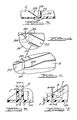
- Figure 3 shows a portion of rib G of corner-center rib pattern 220. This portion is adjacent groove 216 which, in turn, is adjacent medial rib 212.
- Groove 216 weakens plate 100 by reducing its cross-sectional area.
- plate 100 On the side of medial rib 212 away frove groove 216, plate 100 has a thicker cross-section. This thicker cross-section strengthens plate 100 rearward at medial rib 212.
- Rib G has taper 238 that decreases depth of rib G proportional to its distance from groove 216. Taper 238 in rib G prevents resistance by rib G to complete breakaway of forward and rear sections of panel 10.
- Figure 4 shows, in perspective, a section looking in along 11' of Figure 2.
- Figure 4 shows notch 240 taken out of side edge rib 206.
- Notch 240 weakens side edge rib 206.
- Taper 242 in notch 240 in side edge rib 206 prevents resistance to complete breakaway of forward and rear sections of panel 10.
- Figure 5 shows in perspective a section looking in along III' of Figure 2 to show relative disablement of rib H of rib pattern 218 as rib H approaches medial rib 212.
- Taper 244 in rib H provides such relative disablement but also retains a degree of strengthening across medial rib 212.
- Ejector boss 246 Shown, also, in Figure 5 is ejector boss 246.
- Ejector boss 246 as well as other ejector bosses (not shown) distributed at rib intersections throughout panel 10 enable removal (by ejector pins) of panel 10 after it has cured in a mold.
- Figures 6 and 7 illustrate relative dimensions of ribs, bosses and plate that are preferably employed in panel 10 hereinbefore described in detail. These dimensions have reduced susceptibility of panel 10 to show sink after compression molding.
- Depth d of rib R is considerably greater than thickness t of panel 100, e.g., 3 or more times as great.
- depth d of boss B is considerably greater than thickness t of plate 100, e.g., 3 or more times as greater.
- This relationship also follows with respect to the ratio of depth d of rib R to thickness b of rib R.
- dimensions c of ejector boss P and boss Q are kept small, e.g., not more than four times thickness t of plate 100.
- boss dimension e is not more than 10 times thickness t of plate 100, e.g., in a range between 4-7 depending upon the section of plate 100 measured.
- Rib R has thickness b about equal, or even more preferably, substantially less than plate thickness t. Thickness of rib R, for example, may vary from 10-50% less than t depending upon rib location and depending upon thickness of the section of plate 100 measured.
- panels of this invention are not necessarily limited to such characteristics. Rather, for example, thicker and less deep ribs and bosses as well as greater fillet radii will tend to give wider (as measured on the outer surface of plate 100) sink. Such wide sink may prove in certain circumstances, e.g. ribs that follow contours, a desired consequence or so hidden from view as to make no appreciable difference.
- Figures 1-7 particularly relate to, as mentioned, a hood or engine compartment closure panel of a van.
- the panel has front to rear dimension greater than side-to-side dimension, i.e., the length of rib 206 exceeds that of rib 204.
- center-corner and corner-center rib patterns 220 and 218, respectively, of Figure 2 are replaced by rib patterns that extend diagonally from right and left rearward corner areas to respective left and right forward corner areas and form an X-shaped pattern thereby.
- This X-shaped pattern intersects forward of a member weakening pattern similar to that illustrated by Figures 2-6.
- the panel is a decklid and has panel reinforcements and weakening as illustrated in Figures 2-6 but fitted to the geometry of the decklid.
- a procedure for preparation of panel 10 or other such panels is as follows.
- the procedure uses a standard, commercially available compression molding press.
- the mold press has mold members that have temperature control means. These control means maintain a molding temperature between about 275-325°F (135-163°C) more preferably 280-310°F (138-155°G), by usual means.
- the mold members When closed, the mold members provide a cavity conforming to desired panel configuration, e.g. panel 10.
- One of the mold members has chambers that fill during molding to form ribs, bosses, etc.
- the other mold member conforms to a desired outer surface for the panel.
- An operator or device places molding compound between the mold members.
- the molding compound is in layers positioned one atop another.
- the so positioned layers provide a charge pattern that has length and width much larger than its thickness.
- Each layer may be as little as 1/16 inch (0.16 cm) or less thick. Layers with larger thicknesses, e.g., 1/4 inch (0.635 cm) or more, may also be used.
- Figure 8 shows a charge pattern comprising four layers.
- at least layers 1 and 2 (comprising relatively short and relatively long reinforcing fibers respectively) will be of about equally large dimensions (i.e., length and width). When the layers have approximately equal lengths and widths, upward or downward flow between layers is less likely.
- each layer also preferably comprises a low shrink resin, which is more preferably a combination of thermosetting resin thermoplastic resin, such as a polyester and an acrylic resin, respectively.
- the thermoplastic resin reduces shrink of the thermosetting resin during cure.
- a typical preferred resin formulation will have about 20-40 parts thermoplastic resin and about 80-60 parts thermosetting resin including monomers. Molding compound or resin containing thermoplastic resin is commonly referred to as "low profile" molding compound or resin.
- sheet molding compound is made in one process by dropping fiber (e.g., chopped glass) onto a moving bed of formulated resin.
- the formulated resin has been previously spread on a thin sheet of plastic (e.g., polyethylene) which serves as a backing.
- a second resin coated plastic sheet covers the fiber and resin admixture.
- the first and second resin coated plastic sheets have sandwiched between them two layers of formulated resin and one layer of fiber. A sandwich so made may be aged for a period of time.
- the sandwich may be thereafter cut into sections.
- a charge pattern as illustrated in Figure 8 may be made.
- the charge pattern of Figure 8 has three layers (shown as 2, 3 and 4) of one molding compound (comprising thermosetting resin and relatively long fibers) and one layer (shown as 1) of a different molding compound (comprising thermosetting resin and relatively short fibers).
- Each layer may have approximately equal weights of fiber reinforcement and is preferably made from the same resin formulation.
- the resin formulation has a paste viscosity between about 20-30 million centipoise (20-30 . 10 3 Pas) at 25°C. (Paste viscosity refers to viscosity of sheet molding compound without glass or other fiber reinforcement). Paste viscosity between about 20-30 million advantageously reduces porosity of the cured panel.
- Layers 2, 3 and 4 have chopped glass fiber that has an average length of at least three) times the average length of the chopped fiber in layer 1.
- the volume of layers 2, 3 and 4 bears a ratio to the volume of 1 that is substantially equal (within about 25%, more preferably 15%) to the ratio of plate 100 volume to rib and boss volume.
- Fibers lengths that average between 1-3 inches (2.54-7.6 cm) are especially preferred for the relatively long fibers. Fiber lengths that average between about 1/4-3/4 inches (0.635-1.9 cm) are especially preferred for the relatively short fibers. Fibers that average less than about 1/4 inch (0.635 cm) may impart less than optimum desired strength to the reinforcing members.
- an upper mold member When the molding compound is in position between the mold members, an upper mold member preferably closes to cause flow of the molding compound into the cavity.
- the relatively short fibers preferentially flow into the chambers of a bottom mold member.
- the relatively long fibers At the end of the molding cycle, the relatively long fibers have a long axis that lies generally in the plane of plate 100.
- the short fibers, having less resistance to flow, lie more in a plane of the reinforcing members of panel 10. The greater the flow, the more perpendicular to the plate the short fibers become.
- the relative proportion of relatively long fibers to relatively short fibers is preferably such that the relatively long fibers bridge across the top of chambers with the relatively short fibers generally entering the chambers.
- the mold members preferably close slowly, e.g., 3-10 inches per minute, more preferably 4-8 inches (10.16-20.32 cm) per minute. This rate is based upon closure of the mold members after first contact of the molding compound by the mold members.
- the molding press exerts a pressure between about 400-1600 psi (2757-11 ⁇ 3 ⁇ 10 3 Pa) (more preferably 500-1400 psi (3447-9652 . 10 3 Pa)) on the molding compound during closure of the mold members. This pressure causes the molding compound to flow into desired configuration for the panel e.g., panel 10.
- the chambers preferably contain substantially all of the relatively short fibers.
- the remainder of the cavity contains substantially all of the relatively long fibers. In this way discontinuities in flow between long and short fibers is kept as low as possible below the long fibers and the long fibers act as a bridge across areas of potential sink.
- pressure preferably is maintained in a relatively high range for a period of time, e.g. 15-80 seconds. This period, however, tend to reduce sink more. A period between about 15-50 seconds normally enables optimum surface quality of a cured panel.
- a reduction in pressure further significantly enhances surface quality of the cured panel.
- the pressure is reduced to a subsequent pressure of between about 100-800 psi, more preferably between about 150-500 psi (1034-3447 10 3 Pa).
- the ratio of a maximum in the high pressure range to a minimum in the low pressure range may vary, for example, between about 9:1 to 3:2, more preferably between 5:1 to 2:1.
- a pressure reduction during molding is particularly useful with "low profile" resins that contain thermoplastic resin.
- the panel cures at least substantially in the mold.
- a substantial cure occurs after a period of less than about four minutes preferably about 1-3 minutes. Thinner plate panels require a lesser period for cure.
- Layer 1 has 1/2 inch (1.27 cm) chopped glass fiber; layer 2, 3 and 4 have 2 inch chopped glass fiber.
- the layers are about 60x13x1/8 inches (152.4x31,2x0.375 cm) and positioned on the lower mold member equally on either side of center line 200 but slightly rearward, i.e., the lower edge is on rib Y.
- the press is a 1600 ton press.
- the sheet molding compound paste viscosity about 25 million centipose (25.10 3 Pa) at 25°C) has a formulation as follows:
- the molding compound covers about 50% of the lower mold half. Mold close rate is about 5-6 inches (12.7-15.24 cm) per minute. A pressure of 950 psi (6545.5 - 10 3 Pa) after part fillout is maintained for 40 seconds. The pressure is then hydraulically reduced to 400 psi. Cure time is 2 minutes.
- the plate has nearly all the long fibers; the other portion of the panel has nearly all short fibers.
Landscapes
- Engineering & Computer Science (AREA)
- Mechanical Engineering (AREA)
- Chemical & Material Sciences (AREA)
- Combustion & Propulsion (AREA)
- Transportation (AREA)
- Architecture (AREA)
- Structural Engineering (AREA)
- Composite Materials (AREA)
- Manufacturing & Machinery (AREA)
- Civil Engineering (AREA)
- Casting Or Compression Moulding Of Plastics Or The Like (AREA)
- Laminated Bodies (AREA)
- Moulds For Moulding Plastics Or The Like (AREA)
- Moulding By Coating Moulds (AREA)
Description
- This invention relates to a method of producing compression molded fibre reinforced plastics panels.
- A long standing problem with respect to compression moulding of fibre containing thermosetting resin has been surface finish of large structural articles. Particularly difficult problems with respect to production of such articles have been the avoidance of porosity and the removal of surface irregularities commonly referred to as "sink" and "laking". "Sink" is the formation of depressions in the surface of a molded part opposite a rib or boss. "Laking" is a similar defect, but is not associated with a rib or boss.
- US-A-3,903,343 which shows the features of the first part of
claim 1 relates to sink reduction by molding a compound comprising long and short fibres. The short fibres flow into ribs. The weight ratio of short to long fibres is greater than one. - The article "Sink Reduction Techniques for SMC Molding" by Amplthor (33rd Annual Technical Conference, 1978, Reinforced Plastic/Composites Institute, The Society of Plastics Industry, Inc.) describes how certain parameters affect sink. The article illustrates a dual pressure molding cycle as a means to reduce sink. Also, the article describes other parameters that may reduce sink.
- The article "SMK-Sink Mechanisms and Techniques of Minimizing Sink" (Jutte, (Paper 730171) SAE, January 12, 1973) also describes a variety of parameters, including rib design that may reduce sink.
- EP-A1-0 004 531 describes a method of compression molding in which mechanical properties of compression molding composits having thick sections and made from molding compounds comprising thermosetic resin and reinforcing fiber in a thickened dispursion are improved by a preheating stage and mold cycle times that are longer than the time necessary to reach the highest peak exotherm temperature of the composite during molding. Slow post cooling allows for development of properties especially when mold opening times are shorter than that required for removal of all thermal gradients.
- According to the present invention, there is provided a method for producing a compression molded fibre reinforced plastics panel comprising a plate having integrally molded reinforcing ribs on one of its surface, which method comprises:
- A. providing a mold with heated first and second mold members shaped to conform to the desired configuration for said panel;
- B. introducing plastics molding compound between said members, said molding compound comprising a plurality of superimposed layers, a first part of said layers comprising a thermosetting resin and relatively short fibres and the other part of said layers comprising thermosetting resin and relatively long chopped fibres;
- C. closing said mold members upon said molding compound at a pressure in a pressure range sufficient to cause flow of said moulding compound between said mold members;
- D. maintaining said pressure for a period of time; and
- E. parting said mold members and removing said panel from between said mold members.
- F. the plastics molding composition is of a substantially equal paste viscosity in the range of 20-30 103 Pa s at 25°C;
- G. the weight ratio of short fibres to long chopped fibres is not higher than about 1 :2;
- H. the average fibre length ratio of long to short fibers is at least 3:1 ; and
- I. after maintaining the pressure for a period of at least 15 seconds and pressure is reduced to permit said molding compound to cure.
- The invention will now be described further, by way of example, with reference to the drawings, in which:
- Figure 1 shows an external body panel, i.e., engine
compartment closure panel 10, made in accordance with this invention; - Figure 2 shows the underside of
panel 10 of Figure 1; - Figure 3 is a section taken around I'-I' of Figure 2;
- Figures 4 and 5 are perspectives along 11' and III', respectively of Figure 2;
- Figures 6 and 7 show dimensional characteristics of plate, ribs and bosses of
panel 10; and - Figure 8 shows a preferred charge pattern that is compression molded to yield a panel in accordance with this invention.
- This invention is illustrated with reference to the production of a plastic engine compartment closure panel which buckles forward to its rearward edge across its width on an impact that is at its forward edge, said closure panel comprising a plate having a smooth, outer surface and an inner surface bearing integrally formed reinforcing members, and inner surface and reinforcing members having definition comprising:
- A. opposing first and second rib patterns comprising ribs diagonally extending sufficiently across said inner surface so as to intersect one another between said forward and rearward edges and provide torsional rigidty to said panel;
- B. a medial rib pattern comprising a rib that extends along a width of said inner surface
- C. a rearward rib pattern comprising a rib that extends from said medial rib pattern to said rearward edge;
- D. a panel weakening pattern that enables buckling of said member along a line adjacent to said medial rib pattern and comprising:
- 1. a reduction in thickness of said plate forward of said medial rib pattern; (e.g., a groove);
- 2. discontinuities in ribs of said first and second rib patterns at said medial rib pattern.
- Figures 1-7 illustrate an embodiment of this panel; other integrally reinforced panels may also be made in accordance with this invention.
- As shown in Figure 1,
panel 10 fits on what is termed a "van". The embodiment of Figure 1 has advantage vis-a-vis sink identification. That is, relative to engine compartment closure panels of other vehicles, it has (1) greater curvature relative to flat areas and (2) passenger sight lines that are much greater than 0°. Principles of this invention, however, are not limited to an application as in Figure 1; rather, Figure 1 is a current optimal application of principles of this invention. - Figure 2 shows the underside of
panel 10. With the exception of latch 12 and associated fastening means therefor 14 and 16,panel 10 has a composition of fiber reinforced plastics. Reinforced plastic, however, may replace metal latch 12, if further weight reduction is desired. -
Panel 10 comprisesplate 100 with integrally molded reinforcing members as hereinafter particularly described. Sincepanel 10 is symetrically reinforced on either side of center 200 through center rib 202, right integral reinforcing members shall be particularly described hereinafter. -
Panel 10 is affixed to the van through hinge means located at its rearward most right and left corners. The right hinge means (not shown) is mounted by bolts or other affixing means that extend frombosses 226. The bolts are added tobosses 226 after molding. - Latch plate 12 engages a latch mounted to the body of the van to lock it in position after closure. Small X-shaped rib pattern 232 supports a front of
panel 10 when it is in its closed position on the van. - Respective forward and
side edge ribs 204 and 206 project from the underside ofplate 100 at its outermost periphery.Rear periphery edge 208 ofplate 100 is free of edge ribs. Rather, rearward mostrib pattern 210 rigidifies a rear portion ofpanel 100.Rib pattern 210 comprises respective forward and rear ribs X and Y that extend from center rib 202 toside edge rib 206. - Forward of rearward
most rib pattern 210 ismedial rib pattern 212.Medial rib pattern 212 comprises rib M that intersects with center rib 202 andside edge rib 206. - Rearward rib pattern 214 extends between
medial rib 212 and rearwardmost rib pattern 210. Rearward rib pattern 214 comprises ribs A, B, C, D, E, and FF. Rearward rib pattern 214 resists bending ofpanel 100 around an axis extending between center rib 202 andside edge rib 206. - Center-corner and corner-
center rib patterns 220 and 218 comprise, respectively, ribs F and G and ribs H and I. Center-corner and corner-center rib patterns 220 and 218, respectively, along with their corresponding left rib patterns, form, respectively, V-shaped and inverted V-shaped patterns as shown. The V- and inverted V-shaped patterns provide torsional resistance topanel 10. For example, these patterns resist bending ofpanel 10 from its planar surface, when three corners are fixed. Additionally, the rearward portions (of center-corner and corner-center rib patterns 218 and 220) betweenmedial rib pattern 212 and rearward most rib pattern 214 provide a bending resistance about an axis extending between center rib 202 andside edge rib 206. -
Contour rib pattern 222 comprises contour rib J that extends on the underside of a contour ofpanel 100. Contour rib J rigidifies a forward portion ofpanel 100 and extends from underneath latch 12 at center rib 202 toside edge rib 206. Contour rib J is integral with three rear latch plate bosses under plate 12. These rear latch plate bosses accept fastening means 16 that affix a rear portion of latch plate 12 topanel 10. In this way, latch plate 12 is mounted on integrally molded contour rib J and rear latch plate bosses. - Forward most rib pattern 224 provides additional rigidity to
panel 10 near its forward edge. Forward rib pattern 224 comprises forward rib K that extends from underneath latch 12 to a forward rib G of corner-center rib pattern 220. Forward rib G is integral with two forward latch plate bosses under plate 12. These forward latch plate bosses accept fastening means 14 that affix a forward portion of latch plate 12 topanel 10. In this way, latch plate 12 is mounted on integrally molded forward rib G and forward latch plate bosses. -
Boss pattern 226 accepts fastening means such as bolts that project from the interior of individual bosses and accept hinge means (not shown) forpanel 10. Boss pattern 228 accepts additional bolts or other fastening means. These additional bolts affix a hinge support plate (not shown) topanel 10. The hinge support plate provides additional, lateral support for the hinge means. - Flow ribs such as 230 extend from individual bosses to surrounding ribs.
Fow ribs 230 along with other integral ribs assist material flow during molding. Such material flow enables more complete filling of bosses inpatterns 226 and 228. -
Groove 216 extends a width ofpanel 10 between center rib 202 andside edge rib 206. Groove 216 may be made, for example, by routingplate 100 after molding ofpanel 10.Groove 216 weakenspanel 100 along and forward ofmedial rib 212. Upon a frontal impact to the van shown in Figure 1,panel 10 buckles atgroove 216 whereby the part ofpanel 10 that includesmedial rib 212 and portions rearward thereof buckles or otherwise breaks away from the part of forward thereof. - Discontinuity (such as at 234) and other strength disablements of reinforcing members on
panel 10 further assist buckling. Conversely, groove discontinuities ingroove 216 such as at 236 in Figure 2 maintain a degree of strength inpanel 10 alonggroove 216. The effect of groove discontinuity is mitigated, however, by a reduction of rib depth at such discontinuity. The nature of such discontinuity and other inge- grally molded strength modifications topanel 10 may be better seen in Figures 3, 4, and 5 as hereinafter described in greater detail. - More particularly, Figure 3 shows a portion of rib G of corner-center rib pattern 220. This portion is
adjacent groove 216 which, in turn, is adjacentmedial rib 212. -
Groove 216, as mentioned, weakensplate 100 by reducing its cross-sectional area. On the side ofmedial rib 212 awayfrove groove 216,plate 100 has a thicker cross-section. This thicker cross-section strengthensplate 100 rearward atmedial rib 212. Rib G hastaper 238 that decreases depth of rib G proportional to its distance fromgroove 216.Taper 238 in rib G prevents resistance by rib G to complete breakaway of forward and rear sections ofpanel 10. - Figure 4 shows, in perspective, a section looking in along 11' of Figure 2. Figure 4 shows notch 240 taken out of
side edge rib 206.Notch 240 weakensside edge rib 206. Taper 242 innotch 240 inside edge rib 206 prevents resistance to complete breakaway of forward and rear sections ofpanel 10. - Figure 5 shows in perspective a section looking in along III' of Figure 2 to show relative disablement of rib H of
rib pattern 218 as rib H approachesmedial rib 212.Taper 244 in rib H provides such relative disablement but also retains a degree of strengthening acrossmedial rib 212. - Shown, also, in Figure 5 is ejector boss 246. Ejector boss 246 as well as other ejector bosses (not shown) distributed at rib intersections throughout
panel 10 enable removal (by ejector pins) ofpanel 10 after it has cured in a mold. - Figures 6 and 7 illustrate relative dimensions of ribs, bosses and plate that are preferably employed in
panel 10 hereinbefore described in detail. These dimensions have reduced susceptibility ofpanel 10 to show sink after compression molding. - Depth d of rib R is considerably greater than thickness t of
panel 100, e.g., 3 or more times as great. Similarly, depth d of boss B is considerably greater than thickness t ofplate 100, e.g., 3 or more times as greater. This relationship also follows with respect to the ratio of depth d of rib R to thickness b of rib R. Furthermore, dimensions c of ejector boss P and boss Q are kept small, e.g., not more than four times thickness t ofplate 100. Likewise, boss dimension e is not more than 10 times thickness t ofplate 100, e.g., in a range between 4-7 depending upon the section ofplate 100 measured. - As seen by Figures 6 and 7 relatively sharp fillet radii f exists between rib R and
plate 100 and boss Q andplate 100. Further, the draft angle is about 1 ° or less. (Draft angle is defined as the angle shown in Figures 6 and 7, i.e., an angle at which a boss or rib tapers from a line normal to the plate at the boss or rib intersection therewith). Rib R has thickness b about equal, or even more preferably, substantially less than plate thickness t. Thickness of rib R, for example, may vary from 10-50% less than t depending upon rib location and depending upon thickness of the section ofplate 100 measured. - While relatively thin, relatively deep ribs and bosses, as described with reference to Figures 6 and 7, illustrate preferred dimensional characteristics, panels of this invention are not necessarily limited to such characteristics. Rather, for example, thicker and less deep ribs and bosses as well as greater fillet radii will tend to give wider (as measured on the outer surface of plate 100) sink. Such wide sink may prove in certain circumstances, e.g. ribs that follow contours, a desired consequence or so hidden from view as to make no appreciable difference.
- The embodiment of Figures 1-7 particularly relate to, as mentioned, a hood or engine compartment closure panel of a van. In another embodiment, the panel has front to rear dimension greater than side-to-side dimension, i.e., the length of
rib 206 exceeds that of rib 204. In this embodiment, center-corner and corner-center rib patterns 220 and 218, respectively, of Figure 2 are replaced by rib patterns that extend diagonally from right and left rearward corner areas to respective left and right forward corner areas and form an X-shaped pattern thereby. This X-shaped pattern intersects forward of a member weakening pattern similar to that illustrated by Figures 2-6. In still another embodiment the panel is a decklid and has panel reinforcements and weakening as illustrated in Figures 2-6 but fitted to the geometry of the decklid. - A procedure for preparation of
panel 10 or other such panels is as follows. The procedure uses a standard, commercially available compression molding press. The mold press has mold members that have temperature control means. These control means maintain a molding temperature between about 275-325°F (135-163°C) more preferably 280-310°F (138-155°G), by usual means. - When closed, the mold members provide a cavity conforming to desired panel configuration,
e.g. panel 10. One of the mold members has chambers that fill during molding to form ribs, bosses, etc. The other mold member conforms to a desired outer surface for the panel. An operator or device places molding compound between the mold members. The molding compound is in layers positioned one atop another. The so positioned layers provide a charge pattern that has length and width much larger than its thickness. Each layer may be as little as 1/16 inch (0.16 cm) or less thick. Layers with larger thicknesses, e.g., 1/4 inch (0.635 cm) or more, may also be used. - Normally, there will be at least two layers of molding compound, more preferably at least three. Figure 8 shows a charge pattern comprising four layers. As in Figure 8, at
least layers 1 and 2 (comprising relatively short and relatively long reinforcing fibers respectively) will be of about equally large dimensions (i.e., length and width). When the layers have approximately equal lengths and widths, upward or downward flow between layers is less likely. - As mentioned, the layers comprise fiber reinforcement. Each layer also preferably comprises a low shrink resin, which is more preferably a combination of thermosetting resin thermoplastic resin, such as a polyester and an acrylic resin, respectively. The thermoplastic resin reduces shrink of the thermosetting resin during cure. A typical preferred resin formulation will have about 20-40 parts thermoplastic resin and about 80-60 parts thermosetting resin including monomers. Molding compound or resin containing thermoplastic resin is commonly referred to as "low profile" molding compound or resin.
- Production of molding compound as above described is well known. See, for example, US-A-3,903,343. Typically, such compound is referred to as "sheet molding compound". Since sheet molding compound including resins, fibers, fillers, additives etc. is well known and widely available, there is no need for extensive description of its preparation. Briefly, however, sheet molding compound is made in one process by dropping fiber (e.g., chopped glass) onto a moving bed of formulated resin. The formulated resin has been previously spread on a thin sheet of plastic (e.g., polyethylene) which serves as a backing. After fiber has been dropped onto the resin and an admixture made thereby, a second resin coated plastic sheet covers the fiber and resin admixture. Thus, the first and second resin coated plastic sheets have sandwiched between them two layers of formulated resin and one layer of fiber. A sandwich so made may be aged for a period of time.
- The sandwich may be thereafter cut into sections. Upon removal of the plastic sheets, a charge pattern, as illustrated in Figure 8 may be made. The charge pattern of Figure 8 has three layers (shown as 2, 3 and 4) of one molding compound (comprising thermosetting resin and relatively long fibers) and one layer (shown as 1) of a different molding compound (comprising thermosetting resin and relatively short fibers). Each layer may have approximately equal weights of fiber reinforcement and is preferably made from the same resin formulation. The resin formulation has a paste viscosity between about 20-30 million centipoise (20-30 . 103 Pas) at 25°C. (Paste viscosity refers to viscosity of sheet molding compound without glass or other fiber reinforcement). Paste viscosity between about 20-30 million advantageously reduces porosity of the cured panel.
-
Layers layer 1. The volume oflayers plate 100 volume to rib and boss volume. - Fibers lengths that average between 1-3 inches (2.54-7.6 cm) are especially preferred for the relatively long fibers. Fiber lengths that average between about 1/4-3/4 inches (0.635-1.9 cm) are especially preferred for the relatively short fibers. Fibers that average less than about 1/4 inch (0.635 cm) may impart less than optimum desired strength to the reinforcing members.
- When the molding compound is in position between the mold members, an upper mold member preferably closes to cause flow of the molding compound into the cavity. The relatively short fibers preferentially flow into the chambers of a bottom mold member. At the end of the molding cycle, the relatively long fibers have a long axis that lies generally in the plane of
plate 100. The short fibers, having less resistance to flow, lie more in a plane of the reinforcing members ofpanel 10. The greater the flow, the more perpendicular to the plate the short fibers become. The relative proportion of relatively long fibers to relatively short fibers is preferably such that the relatively long fibers bridge across the top of chambers with the relatively short fibers generally entering the chambers. - The mold members preferably close slowly, e.g., 3-10 inches per minute, more preferably 4-8 inches (10.16-20.32 cm) per minute. This rate is based upon closure of the mold members after first contact of the molding compound by the mold members. The molding press exerts a pressure between about 400-1600 psi (2757-11µ3 · 103 Pa) (more preferably 500-1400 psi (3447-9652 . 103 Pa)) on the molding compound during closure of the mold members. This pressure causes the molding compound to flow into desired configuration for the panel e.g.,
panel 10. - When the mold members close upon each other, the chambers preferably contain substantially all of the relatively short fibers. The remainder of the cavity contains substantially all of the relatively long fibers. In this way discontinuities in flow between long and short fibers is kept as low as possible below the long fibers and the long fibers act as a bridge across areas of potential sink.
- After closure of the mold members, pressure preferably is maintained in a relatively high range for a period of time, e.g. 15-80 seconds. This period, however, tend to reduce sink more. A period between about 15-50 seconds normally enables optimum surface quality of a cured panel.
- A reduction in pressure further significantly enhances surface quality of the cured panel. The pressure is reduced to a subsequent pressure of between about 100-800 psi, more preferably between about 150-500 psi (1034-3447 103 Pa). The ratio of a maximum in the high pressure range to a minimum in the low pressure range may vary, for example, between about 9:1 to 3:2, more preferably between 5:1 to 2:1. A pressure reduction during molding is particularly useful with "low profile" resins that contain thermoplastic resin.
- After pressure reduction, the panel cures at least substantially in the mold. A substantial cure occurs after a period of less than about four minutes preferably about 1-3 minutes. Thinner plate panels require a lesser period for cure.
- The following procedures are utilized to provide
panel 10 in accordance with it depicted in Figures 1-7. The charge pattern is depicted in Figure 8.Layer 1 has 1/2 inch (1.27 cm) chopped glass fiber;layer - The press is a 1600 ton press. Dimensions (in inches) of
panel 10 with reference to Figures 6 and 7 are as follows: a=0.06 (0.15 cm); b=0.08 (0.2 cm); c=0.25 (0.635 cm) (ejector pin boss P), 0.24 (0.61 cm) (Boss Q); d=0.70 (1.78 cm) (Rib R), 0.70-1.3 (1.78-3.3 cm) (Boss Q); e=0.63 (1.6 cm); t=0.09-0.15 (0.23-0.38 cm). - The sheet molding compound paste viscosity about 25 million centipose (25.103 Pa) at 25°C) has a formulation as follows:

- The molding compound covers about 50% of the lower mold half. Mold close rate is about 5-6 inches (12.7-15.24 cm) per minute. A pressure of 950 psi (6545.5 - 103 Pa) after part fillout is maintained for 40 seconds. The pressure is then hydraulically reduced to 400 psi. Cure time is 2 minutes.
- The plate has nearly all the long fibers; the other portion of the panel has nearly all short fibers.
- The procedures of Example 1 are followed except that the resin formulation is:

- The results are comparable but less satisfactory relative to those of Example 1 with respect to surface finish.
characterised in that
Claims (13)
characterised in that
Applications Claiming Priority (2)
| Application Number | Priority Date | Filing Date | Title |
|---|---|---|---|
| US06/117,728 US4353857A (en) | 1980-02-01 | 1980-02-01 | Method for making plastic panel and panel |
| US117728 | 1980-02-01 |
Publications (2)
| Publication Number | Publication Date |
|---|---|
| EP0033638A1 EP0033638A1 (en) | 1981-08-12 |
| EP0033638B1 true EP0033638B1 (en) | 1984-12-05 |
Family
ID=22374521
Family Applications (1)
| Application Number | Title | Priority Date | Filing Date |
|---|---|---|---|
| EP81300385A Expired EP0033638B1 (en) | 1980-02-01 | 1981-01-30 | Producing compression molded fibre reinforced plastics panel |
Country Status (5)
| Country | Link |
|---|---|
| US (1) | US4353857A (en) |
| EP (1) | EP0033638B1 (en) |
| JP (1) | JPS56123857A (en) |
| DE (1) | DE3167529D1 (en) |
| MX (1) | MX151669A (en) |
Families Citing this family (30)
| Publication number | Priority date | Publication date | Assignee | Title |
|---|---|---|---|---|
| US4708899A (en) * | 1981-05-11 | 1987-11-24 | Protective Plastics Limited | Laminated panel with integral raised scuff |
| US4855097A (en) * | 1983-04-25 | 1989-08-08 | The Budd Company | Compression molding a charge using vacuum |
| US4612149A (en) * | 1983-04-25 | 1986-09-16 | The Budd Company | Compression molding a charge using vacuum |
| GB2161110B (en) * | 1984-07-07 | 1988-03-23 | Rolls Royce | An annular bladed member having an integral shroud and a method of manufacture thereof |
| US4634167A (en) * | 1985-07-05 | 1987-01-06 | Honda Giken Kogyo Kabushiki Kaisha | Structure for reinforcing automotive cover member of synthetic resin |
| CA1267763A (en) * | 1986-03-19 | 1990-04-17 | Kenneth A. Iseler | Vacuum compression molding method using preheated charge |
| US4808361A (en) * | 1987-03-16 | 1989-02-28 | Gencorp Inc. | Method for forming an in-mold coated fiber reinforced part |
| EP0320302A3 (en) * | 1987-12-10 | 1992-01-02 | General Electric Company | Method and apparatus for making a fiber reinforced composite article |
| US4837914A (en) * | 1988-02-01 | 1989-06-13 | A & S Fiberglass, Inc. | Conversion roof for vans |
| US4937032A (en) * | 1988-05-31 | 1990-06-26 | Phillips Petroleum Company | Method for molding a composite with an integrally molded rib |
| FR2637838B1 (en) * | 1988-10-14 | 1991-01-25 | Europ Propulsion | PROCESS FOR THE MANUFACTURE OF COMPOSITE PARTS MADE OF A SAIL AND A REINFORCEMENT |
| US5089206A (en) * | 1990-05-18 | 1992-02-18 | General Motors Corporation | Dual charge compression molding method |
| US5225135A (en) * | 1991-08-30 | 1993-07-06 | General Motors Corporation | Balanced pressure compression molding method |
| KR100268595B1 (en) * | 1991-12-18 | 2000-10-16 | 고사이 아끼오 | Fiber-reinforced thermoplastic resin molded article and molding method thereof |
| US6551540B1 (en) * | 1998-04-13 | 2003-04-22 | Conix Corporation | Method for overmolding sink marks for an automotive component |
| GB0010156D0 (en) * | 2000-04-27 | 2000-06-14 | Oxford Plastic Sys Ltd | Reinforced moulded article and method of producing same |
| US6439649B1 (en) * | 2001-02-15 | 2002-08-27 | Dow Global Technologies Inc. | Pickup truck box |
| JP2003169986A (en) * | 2001-09-27 | 2003-06-17 | Brother Ind Ltd | Sewing machine frame and sewing machine with sewing machine frame |
| CN100443654C (en) * | 2001-09-27 | 2008-12-17 | 兄弟工业株式会社 | Sewing machine housing with reinforced structure |
| WO2004067360A1 (en) | 2003-01-24 | 2004-08-12 | Club Car, Inc. | Composite body for a golf car and utility vehicle |
| WO2006060720A2 (en) * | 2004-12-02 | 2006-06-08 | Panterra Engineered Plastics, Inc, | Method and apparatus for forming layered thermoformable materials |
| US7837917B2 (en) * | 2006-08-30 | 2010-11-23 | Lrm Industries International, Inc. | Method of forming a molded plastic article having molded extensions |
| US20080057286A1 (en) * | 2006-08-30 | 2008-03-06 | Polk Dale E | Method of forming a molded plastic article having at least one molded extension |
| US20080306752A1 (en) * | 2007-06-08 | 2008-12-11 | Andre Wagner | Method and system for automatic testing in a business scenario environment |
| US20090100781A1 (en) * | 2007-10-23 | 2009-04-23 | Mehdi Hatamian | Modular building system |
| US9409607B2 (en) * | 2014-12-31 | 2016-08-09 | Impact Guard Llc | Composite panel |
| US20180043642A1 (en) * | 2016-08-11 | 2018-02-15 | GM Global Technology Operations LLC | Mold apparatus and method of using the same |
| CN112203926B (en) * | 2018-05-24 | 2023-05-23 | 日产自动车株式会社 | Side panel of vehicle body |
| US10926489B2 (en) * | 2018-07-12 | 2021-02-23 | Arris Composites Inc. | Methods and compositions for compression molding |
| US11498626B2 (en) | 2020-11-11 | 2022-11-15 | Rivian Ip Holdings, Llc | Vehicle tailgate assembly |
Citations (5)
| Publication number | Priority date | Publication date | Assignee | Title |
|---|---|---|---|---|
| DE1629450A1 (en) * | 1951-01-28 | 1971-02-04 | Hawley Products Co | Process for the manufacture of fiber products |
| DE2247047A1 (en) * | 1972-09-26 | 1974-04-04 | Correcta Werke Gmbh | Compression moulded plastic shells - from glass fibre reinforced resin with hollow pressurisable die |
| EP0001865A1 (en) * | 1977-11-03 | 1979-05-16 | Stamicarbon B.V. | Process for making objects from mineral fillers bonded with a thermosetting resin |
| EP0003718A1 (en) * | 1978-02-07 | 1979-08-22 | Hug Interlizenz AG | Synthetic resins reinforced with glass fibres and process for their manufacture |
| EP0004531A1 (en) * | 1977-12-19 | 1979-10-17 | Ford Motor Company Limited | Method of compression molding |
Family Cites Families (6)
| Publication number | Priority date | Publication date | Assignee | Title |
|---|---|---|---|---|
| DE1107396B (en) * | 1954-12-14 | 1961-05-25 | Richard Jonke | Process for the production of reinforced or stiffened plastic molded parts by injection molding |
| US2997096A (en) * | 1957-05-16 | 1961-08-22 | Owens Corning Fiberglass Corp | Multiple stage methods and apparatus for curing the binder of fibrous glass masses |
| US3903343A (en) * | 1972-06-20 | 1975-09-02 | Rohm & Haas | Method for reducing sink marks in molded glass fiber reinforced unsaturated polyester compositions, and molded articles thereby produced |
| JPS50117879A (en) * | 1974-03-04 | 1975-09-16 | ||
| US4081578A (en) * | 1974-06-27 | 1978-03-28 | The General Tire & Rubber Company | In-mold coating composition and method of applying same |
| US4051290A (en) * | 1975-11-10 | 1977-09-27 | Owens-Corning Fiberglas Corporation | Sink-free panels |
-
1980
- 1980-02-01 US US06/117,728 patent/US4353857A/en not_active Expired - Lifetime
-
1981
- 1981-01-27 MX MX185719A patent/MX151669A/en unknown
- 1981-01-28 JP JP1030181A patent/JPS56123857A/en active Pending
- 1981-01-30 DE DE8181300385T patent/DE3167529D1/en not_active Expired
- 1981-01-30 EP EP81300385A patent/EP0033638B1/en not_active Expired
Patent Citations (5)
| Publication number | Priority date | Publication date | Assignee | Title |
|---|---|---|---|---|
| DE1629450A1 (en) * | 1951-01-28 | 1971-02-04 | Hawley Products Co | Process for the manufacture of fiber products |
| DE2247047A1 (en) * | 1972-09-26 | 1974-04-04 | Correcta Werke Gmbh | Compression moulded plastic shells - from glass fibre reinforced resin with hollow pressurisable die |
| EP0001865A1 (en) * | 1977-11-03 | 1979-05-16 | Stamicarbon B.V. | Process for making objects from mineral fillers bonded with a thermosetting resin |
| EP0004531A1 (en) * | 1977-12-19 | 1979-10-17 | Ford Motor Company Limited | Method of compression molding |
| EP0003718A1 (en) * | 1978-02-07 | 1979-08-22 | Hug Interlizenz AG | Synthetic resins reinforced with glass fibres and process for their manufacture |
Also Published As
| Publication number | Publication date |
|---|---|
| DE3167529D1 (en) | 1985-01-17 |
| JPS56123857A (en) | 1981-09-29 |
| US4353857A (en) | 1982-10-12 |
| EP0033638A1 (en) | 1981-08-12 |
| MX151669A (en) | 1985-01-30 |
Similar Documents
| Publication | Publication Date | Title |
|---|---|---|
| US4353857A (en) | Method for making plastic panel and panel | |
| US12214648B2 (en) | Hybrid composite tailgate | |
| US6843525B2 (en) | Reinforced composite vehicle load floor of the cellular core sandwich-type | |
| EP0592633B1 (en) | Fibrous bumper preform, apparatus and method of forming same | |
| US4308307A (en) | Plastic panel for vehicular exterior | |
| CN107521124A (en) | Carbon fiber dual platen reinforced structure part and its manufacture method | |
| EP1015297B1 (en) | Exterior autobody part of reinforced plastic, and arrangement and method for its forming | |
| JPS59199227A (en) | Production of bamper | |
| CN115180026B (en) | Composite engine cover and manufacturing method thereof | |
| EP0563670A1 (en) | Method for forming shower-trays, bathtubs, wash-basins and floor toilets of plastics material and the products obtained | |
| CN218197859U (en) | Automobile door plate | |
| EP3668778B1 (en) | Closed structural component and a process for preparing the same | |
| CN115195420A (en) | Automobile door plate | |
| CN107433723B (en) | Method for manufacturing spare and accessory parts | |
| US20210308970A1 (en) | Molded laminated structure with negative draft angles and associated methods of manufacturing | |
| JP2571276Y2 (en) | Core material for molding fiber-reinforced resin | |
| JP2005526638A (en) | Method for coating a component made of fiber reinforced plastic and component formed by the method | |
| JP3259361B2 (en) | Molding method of FRP molded product | |
| US20240101230A1 (en) | Board with board bumper | |
| CN101180169A (en) | Processes and tools for forming structural sheets | |
| JP2511169B2 (en) | Golf club head and manufacturing method thereof | |
| JPH0614987Y2 (en) | Back mold structure for synthetic resin molding | |
| JPH07171887A (en) | End treatment method for resin molded products | |
| JPH04214313A (en) | Manufacture of laminated molding of frp structure | |
| JPH0736711U (en) | Toecaps for safety shoes |
Legal Events
| Date | Code | Title | Description |
|---|---|---|---|
| PUAI | Public reference made under article 153(3) epc to a published international application that has entered the european phase |
Free format text: ORIGINAL CODE: 0009012 |
|
| AK | Designated contracting states |
Designated state(s): DE FR GB |
|
| 17P | Request for examination filed |
Effective date: 19811109 |
|
| RAP1 | Party data changed (applicant data changed or rights of an application transferred) |
Owner name: FORD FRANCE SOCIETE ANONYME Owner name: FORD-WERKE AKTIENGESELLSCHAFT Owner name: FORD MOTOR COMPANY LIMITED |
|
| GRAA | (expected) grant |
Free format text: ORIGINAL CODE: 0009210 |
|
| AK | Designated contracting states |
Designated state(s): DE FR GB |
|
| PGFP | Annual fee paid to national office [announced via postgrant information from national office to epo] |
Ref country code: FR Payment date: 19841220 Year of fee payment: 5 |
|
| REF | Corresponds to: |
Ref document number: 3167529 Country of ref document: DE Date of ref document: 19850117 |
|
| ET | Fr: translation filed | ||
| PGFP | Annual fee paid to national office [announced via postgrant information from national office to epo] |
Ref country code: DE Payment date: 19850226 Year of fee payment: 5 |
|
| PLBI | Opposition filed |
Free format text: ORIGINAL CODE: 0009260 |
|
| 26 | Opposition filed |
Opponent name: BAYER AG, LEVERKUSEN KONZERNVERWALTUNG RP PATENTAB Effective date: 19850905 Opponent name: M.A.N. MASCHINENFABRIK AUGSBURG-NUERNBERG AKTIENGE Effective date: 19850905 Opponent name: MENZOLIT-WERKE ALBERT SCHMIDT GMBH & CO. KG Effective date: 19850904 |
|
| RDAG | Patent revoked |
Free format text: ORIGINAL CODE: 0009271 |
|
| STAA | Information on the status of an ep patent application or granted ep patent |
Free format text: STATUS: PATENT REVOKED |
|
| 27W | Patent revoked |
Effective date: 19870917 |
|
| GBPR | Gb: patent revoked under art. 102 of the ep convention designating the uk as contracting state | ||
| REG | Reference to a national code |
Ref country code: GB Ref legal event code: 7102 |