EP0032122B1 - Gravity feed merchandise dispensing device - Google Patents
Gravity feed merchandise dispensing device Download PDFInfo
- Publication number
- EP0032122B1 EP0032122B1 EP19810300001 EP81300001A EP0032122B1 EP 0032122 B1 EP0032122 B1 EP 0032122B1 EP 19810300001 EP19810300001 EP 19810300001 EP 81300001 A EP81300001 A EP 81300001A EP 0032122 B1 EP0032122 B1 EP 0032122B1
- Authority
- EP
- European Patent Office
- Prior art keywords
- rails
- track
- flange
- pair
- web
- Prior art date
- Legal status (The legal status is an assumption and is not a legal conclusion. Google has not performed a legal analysis and makes no representation as to the accuracy of the status listed.)
- Expired
Links
Images


Classifications
-
- A—HUMAN NECESSITIES
- A47—FURNITURE; DOMESTIC ARTICLES OR APPLIANCES; COFFEE MILLS; SPICE MILLS; SUCTION CLEANERS IN GENERAL
- A47F—SPECIAL FURNITURE, FITTINGS, OR ACCESSORIES FOR SHOPS, STOREHOUSES, BARS, RESTAURANTS OR THE LIKE; PAYING COUNTERS
- A47F7/00—Show stands, hangers, or shelves, adapted for particular articles or materials
- A47F7/28—Show stands, hangers, or shelves, adapted for particular articles or materials for containers, e.g. flasks, bottles, tins, milk packs
- A47F7/285—Show stands having fixation means, e.g. hanging means, slidable fixations, frictional retaining means, theft prevention
-
- A—HUMAN NECESSITIES
- A47—FURNITURE; DOMESTIC ARTICLES OR APPLIANCES; COFFEE MILLS; SPICE MILLS; SUCTION CLEANERS IN GENERAL
- A47F—SPECIAL FURNITURE, FITTINGS, OR ACCESSORIES FOR SHOPS, STOREHOUSES, BARS, RESTAURANTS OR THE LIKE; PAYING COUNTERS
- A47F1/00—Racks for dispensing merchandise; Containers for dispensing merchandise
- A47F1/04—Racks or containers with arrangements for dispensing articles, e.g. by means of gravity or springs
- A47F1/12—Racks or containers with arrangements for dispensing articles, e.g. by means of gravity or springs dispensing from the side of an approximately horizontal stack
Definitions
- This invention relates to a merchandise dispensing device of the gravity feed type.
- the device is particularly useful together with other such devices in forming a compact, automatic feed merchandise display rack.
- Merchandise display racks of the gravity feed type are used where it is desirable that articles of merchandise for sale successively are advanced forwardly of the rack so that they are always in view of, and readily accessible to the customer.
- One aspect of this invention utilizes to advantage the provision of neck flanges on such bottles by providing a merchandising device which allows the bottles to be suspended by their neck flanges.
- the manner in which the bottles are suspended in the device according to the present invention is similar to the manner in which bottles are suspended in the well known soft drink vending machines having a series of parallel metal rails arranged to provide parallel slots for holding bottles underneath their neck flanges.
- a gravity feed merchandise dispensing device which con- prises track means having an upper pair of rails and a lower pair of rails both of which are adapted to support two rows of similar bottles of the type having an annular flange on the neck of the bottle, one row above the other.
- the track means is inclined (downwardly) so as to permit the suspended bottles to gravity feed one after the other to the front end of the track means as the lead bottles in the row successively are unloaded, and stop means is provided adjacent said front end of the track to arrest movement of each lead bottle.
- this prior construction is not one in which either of the two pairs of rails can be brought into a lower functional position whilst the other pair of rails is thereby put into an upper non-functional position.
- the present invention gives a dispensing device able to accommodate a variety of bottles having neck flanges of different dimension.
- the stop means of the present construction is provided by an upturned portion of the lower functional pair of rails.
- the invention provides a gravity feed merchandise dispensing device comprising at least one track means having a front and a rear end for supporting in tandem a row of similar bottles of the type having an annular flange on the neck of the bottle, each track means comprising a pair of rails, the rails being spaced apart to receive between them the necks of suitably sized bottles such that the underside of each neck flange engages the rails whereby the bottles are suspended by their flanges for movement relative to the track means, each track means normally being downwardly inclined towards the front end so as to permit the suspended bottles to gravity feed one after the other to the front end of the track means as the lead bottles in the row successively are unloaded, said front end of said track means including stop means whereby movement of each lead bottle is arrested, and means being provided for supporting said track means in a fixed position, characterised in that the track means has an additional pairs of rails and is adjustable relative to the support so as to bring either one of the pairs of rails into a lower functional position in which bottles are received thereon, thereby
- each track includes two pairs of rails.
- the track 36 comprises an upper pair of rails 37 and a lower pair of rails 38 which are connected together as described hereinafter.
- each of the rails 37, 38 is provided with a stop portion 37a. 38a, respectively, at its end which is upturned relative to the remainder of the rail when that rail is on a lower functional position.
- the lead bottles received on the tracks do not leave the rails when arriving at their dispensing positions.
- the lead bottles gravity feed down the track and are braked to a stop causing those bottles to move along an inclined path provided by the upturned front portions of the lower rails.
- Track component 39 includes a pair of generally channel section elements 41, 42 each having a base portion 41a, 42a respectively. Upstanding from base 41a is a pair of integral divergent limbs 41b, 41c which terminate in outwardly projecting flanges 41d, 41e respectively. Each of the flanges 41d and 41e provides an upper rail for adjacent tracks.
- the channel section element 42 includes a pair of integral divergent limbs 42b, 42c extending from base 42a.
- the limbs 42b, 42c terminate in outwardly projecting flanges 42d, 42e each of which provides a lower rail for adjacent tracks.
- track component 40 which is only partially shown includes rail flanges 43d and 44d projecting from channel section elements 43 and 44 respectively.
- the flanges 41e and 43d are spaced apart by a distance 'x' and provide an upper pair of rails on which the neck flange of a suitable bottle can slide.
- the flanges 4e and 44d are spaced apart by a distance 'y' and provide a lower pair of rails on which the neck flange of a suitable bottle can slide.
- Distance 'x' is greater than distance 'y' so that bottles having two different standard diameter neck flanges can be received in the tracks.
- the distance 'z' is chosen to be such as to provide sufficient space in which to receive the tops of the bottles.
- tie-bars 45, 46 extends across the rear end of the upper rails 37 and the tie-bar 46 extends across the rear end of the lowermost rails 38.
- This feature of course, allows the lead bottles 50 to be disposed in a readily accessible position at the front end of the tracks for removal by a prospective customer.
- the angle of the incline can of course be varied to increase or decrease the braking effect desired as can the angle at which the tracks are mounted in the stand.
- FIG. 3 to 8 of the drawing illustrate a preferred embodiment of the invention.
- a beverage display stand or "merchandiser” in accordance with the preferred embodiment of the invention comprises one or more track support units of the kind shown in Figure 3 removably mounted on a rack (not shown).
- the rack can be a conventional four-post rack or alternatively a rack consisting of a base having a vertically extending back wall on which the track support units are cantilevered.
- each merchandiser will have several track support units arranged one above another.
- the track support unit in Figure 3 is designed for use in a four-post rack. It is formed entirely of sheet metal, and comprises side members 51 and 52, cross members 53 and 54, and a nunber of tracks, only one of which is shown. Each track comprises removable elongate elements 55 and 56.
- Side members 51 and 52 have an inverted L-shaped transverse cross-section. Hooks are formed at the ends of the side members at 57, 58, 59 and 60. These hooks are adapted to engage slots in the four-post rack. If desired in a four-post system, the side members can be identical to each other since the front and rear hooks can be symmetrical. When the track support is designed for use in a rack having a back extending upwardly from the rear of a base, the side members are designed differently, and are provided with special slot-engaging tabs such as those shown in Suttles USA-A-3,983,822.
- Transverse elements 53 and 54 are preferably identical and have cross-sections of the shape shown in Figure 8. Elements 53 and 54 extend between side elements 51 and 52, and are secured underneath the horizontal flanges of elements 51 und 52 by spot welding, or by suitable fasteners. Transverse element 53 is positioned near the front of the track support unit, while transverse element 54 is positioned near the rear of the unit.
- the transverse elements support the elongate elements so that the track slopes downwardly and forewardly at a small angle, e.g. 10 degrees, to allow bottles to be carried to the front of the track by gravity.
- each transverse element of the track support unit comprises a horizontal web 61 for attachment to the side elements, a rear, L-shaped reinforcing flange 62, and a depending front flange 63.
- flange 63 of transverse element 53 is provided with a series of evenly spaced slots of complex shape. The slots in element 53 are indicated at 64, 65, 66 and 67.
- Slot 64 comprises a horizontal edge 68 which is parallel to and spaced upwardly from lower edge 69 of flange 63. At its left-hand end, flange 63 curves downwardly at 70, to meet another horizontal, downwardly facing edge 71, which is positioned at a level below edge 68. Horizontal edge 71 is the upper boundary of an opening 72, the lower boundary of which, at 73, is the upper edge of a horizontal extension 74. At the right-hand end of horizontal extension 74, there is provided a vertical extension 75 having a horizontal upper edge 76, and an upwardly extending tab 77.
- the left-hand edge 78 of extension 75 extends obliquely from lower boundary 73 of opening 72 to horizontal edge 76.
- Horizontal edge 76 is positioned at a level below the level of downwardly facing edge 71, the vertical spacing between these two edges being equal to the thickness of the sheet metal from which the elongate elements are made.
- Opening 72 should be large enough to provide clearance for the larger of the two elongate element flanges.
- the configuration of the right-hand end of slot 64 is a mirror image of the configuration of the left-hand end, and need not be separately described.
- the two elongate elements 55 and 56 are preferably identical and elongate element 56 is shown in detail in Figure 4.
- the elongate element is formed from a unitary piece of sheet metal, and comprises a vertical web 79 having a first flange 80 extending perpendicularly from its upper edge, and a second flange 81 extending perpendicularly from its lower edge in the opposite direction.
- Flange 81 is wider than flange 80.
- flange 80 is separated from the upper edge of the web, and is bent downwardly at 82 to form an obtuse angle (e.g. approximately 138°) with the main part of flange 80 to provide a ramp 83.
- Ramp 83 terminates in a flange 84 which is substantially perpendicular to ramp 83, and extends downwardly therefrom.
- a similar ramp 85 is formed at the opposite end of flange 80, and terminates in a downwardly extending flange 86.
- Flange 80 is provided with a small opening 87 spaced a short distance from bend 82. Opening 87 is positioned adjacent web 79. A similar opening 88 in flange 80 is spaced from bend 89 by a distance equal to the spacing between opening 87 and bend 82.
- Wide flange 81 on the opposite side of the track member is similarly bent to provide ramps 90 and 91, which terminate respectively in flanges 92 and 93.
- Flange 81 is also provided with openings (not shown) corresponding to openings 87 and 88, and the openings in flange 81 are at the same longitudinal positions as openings 87 and 88.
- Figure 5 shows elongate element 56 installed in slot 64.
- the right-hand face 94 of web 79 bears against vertical edge 95, while the underside of flange 80 bears against horizontal edge 96.
- Tab 97 extends upwardly through opening 87.
- a similar elongate element 98 is supported on the opposite side of slot 64 in the same manner.
- Flanges 81 and 99 of the respective elongate elements have parallel edges 100 and 101 which form a slot for receiving the neck 102 of bottle 103.
- Bottle 103 has an outwardly projecting annular neck flange 104, which extends beyond edges 100 and 101, thereby permitting the bottle to be supported by engagement of neck flange 104 with the upwardly facing side of flanges 99 and 81.
- the weight of the bottle causes face 94 of the web 79 to bear against vertical edge 95, while the engagement of tab 97 in opening 87 prevents the web from rotating away from edge 95.
- the weight on track element 56 is supported by edge 96.
- the track can be modified to accommodate larger bottles such as bottle 105.
- an elongate element such as element 98
- element 98 is easily installed by tilting the element, and causing its upper flange to enter opening 72, and thereafter rotating the element until tab 77 enters opening 108.
- the manipulation of the element in installation also involves the engagement of the element in a similar manner with the rear transverse track support element 54 ( Figure 3).
- soft drink bottle 109 is shown held in the track comprising elongate elements 55 and 56. As bottle 109 slides down the track, it will normally reach the position indicated by bottle 110, which is shown in broken lines.
- the bottles behind the foremost bottle in a track cause the foremost bottle to assume the tilted position indicated at 110.
- the bottle at 110 is removed by a customer simply by lifting it upwardly in order to cause its neck ring to clear the upwardly extending tabs at the ends of the ramps. By reason of the presence of the ramps and the tabs at the ends of the ramps, the bottle behind the foremost bottle is prevented from causing accidental disengagement of the foremost bottle from the track.
- An important feature of this aspect of the invention is the prevention of a "see-saw" effect, which could cause accidental disengagement of the removable elongate elements from their supports when a single bottle is positioned at the front of the track.
- the weight of a bottle positioned forward of front cross member 53 causes the elongate elements to tend to pivot about the front cross member.
- the rear ends of the elongate elements are urged upwardly with a resulting tendency for the elongate elements to become disengaged from the rear cross member 54.
- Such disengagement is prevented by reason of the fact that the upper flange of each elongate element is in engagement with a downwardly facing edge corresponding to edge 71 in Figure 7. So long as at least one bottle is present in the track, the engagement between the upper flange and the downwardly facing edge is maintained. Consequently, the elongate elements of a particular track cannot be removed from the track support unit until all of the bottles are removed from the track.
- the merchandising device in accordance with this embodiment of the invention has numerous advantages including its structural simplicity, ease of manufacture, ease of conversion to accommodate bottles with different neck sizes, its small vertical space requirement, the ease with which bottles can be removed from its tracks, the prevention of accidental removal of bottles, and the simple manner in which the elongate elements are locked in place so long as bottles are present in the track.
- the device gives rise to a number of additional advantages not previously mentioned. For example, since the slot widths of the tracks can be changed individually, this merchandising device gives the merchant a high degree of flexibility; he can place large- necked and small-necked bottles on adjacent tracks if he so chooses. It is possible to accommodate three different sizes of bottles with two identical elongate elements of the type shown in Figure 4. It is also possible to accommodate four different bottle sizes, using a pair of non-identical elongate elements.
- the entire track unit of Figure 3 can be constructed from elements of only three different types, since elements 53 and 54 can be identical, elements 51 and 52 can be identical, and elements 55 and 56 can be identical.
- the elongate elements can be made with cross-sectional shapes other than the Z-shapes shown.
- the track elements can be L-shaped, in which event the two legs of the L are usable alternatively as supporting surfaces for the neck flanges of the bottles.
- the elongate elements can also be C-shaped.
Description
- This invention relates to a merchandise dispensing device of the gravity feed type. The device is particularly useful together with other such devices in forming a compact, automatic feed merchandise display rack.
- Merchandise display racks of the gravity feed type are used where it is desirable that articles of merchandise for sale successively are advanced forwardly of the rack so that they are always in view of, and readily accessible to the customer.
- In recent years large capacity bottles made from plastics material have been developed for the sale of e.g. soft drinks. Such bottles are tall and relatively light in comparison to their size and do exhibit some degree of instability when free standing, particularly if used on known merchandising display devices.
- Many of these large capacity plastics bottles are formed with a projecting flange around the bottle neck used as a gripping element for handling the bottle prior to the point of sale. One aspect of this invention utilizes to advantage the provision of neck flanges on such bottles by providing a merchandising device which allows the bottles to be suspended by their neck flanges. The manner in which the bottles are suspended in the device according to the present invention is similar to the manner in which bottles are suspended in the well known soft drink vending machines having a series of parallel metal rails arranged to provide parallel slots for holding bottles underneath their neck flanges.
- From FR-A-2 166 285 a gravity feed merchandise dispensing device is shown which con- prises track means having an upper pair of rails and a lower pair of rails both of which are adapted to support two rows of similar bottles of the type having an annular flange on the neck of the bottle, one row above the other. The track means is inclined (downwardly) so as to permit the suspended bottles to gravity feed one after the other to the front end of the track means as the lead bottles in the row successively are unloaded, and stop means is provided adjacent said front end of the track to arrest movement of each lead bottle.
- However, this prior construction is not one in which either of the two pairs of rails can be brought into a lower functional position whilst the other pair of rails is thereby put into an upper non-functional position. By providing a difference in spacing between the rails, one pair to that between the rails of the other pair, the present invention gives a dispensing device able to accommodate a variety of bottles having neck flanges of different dimension. Moreover, the stop means of the present construction is provided by an upturned portion of the lower functional pair of rails.
- The invention provides a gravity feed merchandise dispensing device comprising at least one track means having a front and a rear end for supporting in tandem a row of similar bottles of the type having an annular flange on the neck of the bottle, each track means comprising a pair of rails, the rails being spaced apart to receive between them the necks of suitably sized bottles such that the underside of each neck flange engages the rails whereby the bottles are suspended by their flanges for movement relative to the track means, each track means normally being downwardly inclined towards the front end so as to permit the suspended bottles to gravity feed one after the other to the front end of the track means as the lead bottles in the row successively are unloaded, said front end of said track means including stop means whereby movement of each lead bottle is arrested, and means being provided for supporting said track means in a fixed position, characterised in that the track means has an additional pairs of rails and is adjustable relative to the support so as to bring either one of the pairs of rails into a lower functional position in which bottles are received thereon, thereby automatically putting the other pair of rails into an upper non-functional position, in that the rails of one of the pairs are spaced apart by a distance which differs from that between the rails of said other pair and in that said stop means is provided by an upturned portion of the lower functional pair of rails.
- In the following description embodiments of the invention are described by way of example with reference to the accompanying drawings, in which:-
- FIGURE 1 is a side view of a track of a gravity feed merchandise dispensing device;
- FIGURE 2 is a cross-section through a series of the tracks, shown in FIGURE 1;
- FIGURE 3 is an oblique perspective view showing a track support unit in accordance with another embodiment of the invention with a track installed in it comprising a pair of elongate elements;
- FIGURE 4 is an oblique perspective view of a single elongate element;
- FIGURE 5 is a transverse section of a track showing the manner in which a pair of elongate elements cooperate with the support and with a bottle;
- FIGURE 6 is a transverse section similar to FIGURE 8 except that the elongate elements are reversed in order to accommodate a larger bottle;
- FIGURE 7 is a tranverse section of a track illustrating the manner in which the elongate elements are installed and removed and,
- FIGURE 8 is a vertical section of a support member taken on the plane 10-10 indicated in FIGURE 3.
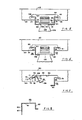
- Referring first to FIGURES 1 and 2, there is shown a track construction in which each track includes two pairs of rails. The
track 36 comprises an upper pair ofrails 37 and a lower pair ofrails 38 which are connected together as described hereinafter. To arrest movement of each lead bottle each of therails stop portion 37a. 38a, respectively, at its end which is upturned relative to the remainder of the rail when that rail is on a lower functional position. Thus, the lead bottles received on the tracks do not leave the rails when arriving at their dispensing positions. In the construction shown, the lead bottles gravity feed down the track and are braked to a stop causing those bottles to move along an inclined path provided by the upturned front portions of the lower rails. The track construction is shown in more detail in FIGURE 2 of the drawings. Each track is provided by a pair of adjacent track components such as those designated by thereference numerals Track component 39 includes a pair of generallychannel section elements 41, 42 each having abase portion 41a, 42a respectively. Upstanding from base 41a is a pair of integraldivergent limbs 41b, 41c which terminate in outwardly projectingflanges 41d, 41e respectively. Each of theflanges 41d and 41e provides an upper rail for adjacent tracks. - Similarly, the
channel section element 42 includes a pair of integraldivergent limbs 42b, 42c extending frombase 42a. Thelimbs 42b, 42c terminate in outwardly projectingflanges track component 40 which is only partially shown includesrail flanges - The
flanges flanges 4e and 44d are spaced apart by a distance 'y' and provide a lower pair of rails on which the neck flange of a suitable bottle can slide. Distance 'x' is greater than distance 'y' so that bottles having two different standard diameter neck flanges can be received in the tracks. The distance 'z' is chosen to be such as to provide sufficient space in which to receive the tops of the bottles. Of course, whichever rail size is required for use needs to be located lowermost in the device and this may be achieved simply by removing the track components from the support stand, turning over the track components and then replacing them in the stand. It is also envisaged that such rail 'reversal' can be achieved by installing each series of tracks so that they are pivotally mounted within the stand. - The track components are connected together by means of tie-
bars 45, 46 (see Figure 1). As can be seen tie-bar 45 extends across the rear end of theupper rails 37 and the tie-bar 46 extends across the rear end of thelowermost rails 38. - In order to assemble a series of tracks in a suitable stand such as that shown in Figure 1 it is simply necessary to provide a
suitable channel 47 into which the back ends of the track components can be slotted (Figure 1) and a pin andfork assembly fork assembly lead bottles 50 to be disposed in a readily accessible position at the front end of the tracks for removal by a prospective customer. The angle of the incline can of course be varied to increase or decrease the braking effect desired as can the angle at which the tracks are mounted in the stand. - Figures 3 to 8 of the drawing illustrate a preferred embodiment of the invention.
- Referring to Figure 3, a beverage display stand or "merchandiser" in accordance with the preferred embodiment of the invention comprises one or more track support units of the kind shown in Figure 3 removably mounted on a rack (not shown). The rack can be a conventional four-post rack or alternatively a rack consisting of a base having a vertically extending back wall on which the track support units are cantilevered. In general, each merchandiser will have several track support units arranged one above another.
- The track support unit in Figure 3 is designed for use in a four-post rack. It is formed entirely of sheet metal, and comprises
side members cross members elongate elements 55 and 56. -
Side members -
Transverse elements Elements side elements elements 51 und 52 by spot welding, or by suitable fasteners.Transverse element 53 is positioned near the front of the track support unit, whiletransverse element 54 is positioned near the rear of the unit. - The transverse elements support the elongate elements so that the track slopes downwardly and forewardly at a small angle, e.g. 10 degrees, to allow bottles to be carried to the front of the track by gravity.
- Referring first to Figure 8, each transverse element of the track support unit comprises a
horizontal web 61 for attachment to the side elements, a rear, L-shaped reinforcingflange 62, and a dependingfront flange 63. As shown in Figure 3,flange 63 oftransverse element 53 is provided with a series of evenly spaced slots of complex shape. The slots inelement 53 are indicated at 64, 65, 66 and 67. - The complex shape of the slots is best seen in Figure 7 which shows the details of
slot 64.Slot 64 comprises ahorizontal edge 68 which is parallel to and spaced upwardly fromlower edge 69 offlange 63. At its left-hand end,flange 63 curves downwardly at 70, to meet another horizontal, downwardly facingedge 71, which is positioned at a level belowedge 68.Horizontal edge 71 is the upper boundary of anopening 72, the lower boundary of which, at 73, is the upper edge of ahorizontal extension 74. At the right-hand end ofhorizontal extension 74, there is provided avertical extension 75 having a horizontalupper edge 76, and an upwardly extendingtab 77. - Preferably, the left-
hand edge 78 ofextension 75 extends obliquely fromlower boundary 73 of opening 72 tohorizontal edge 76.Horizontal edge 76 is positioned at a level below the level of downwardly facingedge 71, the vertical spacing between these two edges being equal to the thickness of the sheet metal from which the elongate elements are made.Opening 72 should be large enough to provide clearance for the larger of the two elongate element flanges. - The configuration of the right-hand end of
slot 64 is a mirror image of the configuration of the left-hand end, and need not be separately described. - The two
elongate elements 55 and 56 are preferably identical andelongate element 56 is shown in detail in Figure 4. The elongate element is formed from a unitary piece of sheet metal, and comprises avertical web 79 having afirst flange 80 extending perpendicularly from its upper edge, and asecond flange 81 extending perpendicularly from its lower edge in the opposite direction. Thus, throughout most of its length, the elongate element has a Z-shaped cross-section.Flange 81 is wider thanflange 80. - At the front end of
elongate element 56,flange 80 is separated from the upper edge of the web, and is bent downwardly at 82 to form an obtuse angle (e.g. approximately 138°) with the main part offlange 80 to provide aramp 83.Ramp 83 terminates in aflange 84 which is substantially perpendicular to ramp 83, and extends downwardly therefrom. Asimilar ramp 85 is formed at the opposite end offlange 80, and terminates in a downwardly extendingflange 86. -
Flange 80 is provided with asmall opening 87 spaced a short distance frombend 82.Opening 87 is positionedadjacent web 79. Asimilar opening 88 inflange 80 is spaced frombend 89 by a distance equal to the spacing betweenopening 87 andbend 82. -
Wide flange 81 on the opposite side of the track member is similarly bent to provideramps flanges Flange 81 is also provided with openings (not shown) corresponding toopenings flange 81 are at the same longitudinal positions asopenings - Figure 5 shows
elongate element 56 installed inslot 64. The right-hand face 94 ofweb 79 bears againstvertical edge 95, while the underside offlange 80 bears againsthorizontal edge 96.Tab 97 extends upwardly throughopening 87. A similarelongate element 98 is supported on the opposite side ofslot 64 in the same manner.Flanges parallel edges neck 102 ofbottle 103.Bottle 103 has an outwardly projectingannular neck flange 104, which extends beyondedges neck flange 104 with the upwardly facing side offlanges web 79 to bear againstvertical edge 95, while the engagement oftab 97 in opening 87 prevents the web from rotating away fromedge 95. The weight ontrack element 56 is supported byedge 96. - In Figure 6
elongate elements larger bottle 105 rests onshorter flanges longer flanges surfaces - By simply reversing the elongate elements, the track can be modified to accommodate larger bottles such as
bottle 105. - As shown in Figure 7, an elongate element, such as
element 98, is easily installed by tilting the element, and causing its upper flange to enteropening 72, and thereafter rotating the element untiltab 77 entersopening 108. The manipulation of the element in installation, of course, also involves the engagement of the element in a similar manner with the rear transverse track support element 54 (Figure 3). - Returning to Figure 3,
soft drink bottle 109 is shown held in the track comprisingelongate elements 55 and 56. Asbottle 109 slides down the track, it will normally reach the position indicated by bottle 110, which is shown in broken lines. The bottles behind the foremost bottle in a track cause the foremost bottle to assume the tilted position indicated at 110. The bottle at 110 is removed by a customer simply by lifting it upwardly in order to cause its neck ring to clear the upwardly extending tabs at the ends of the ramps. By reason of the presence of the ramps and the tabs at the ends of the ramps, the bottle behind the foremost bottle is prevented from causing accidental disengagement of the foremost bottle from the track. - An important feature of this aspect of the invention is the prevention of a "see-saw" effect, which could cause accidental disengagement of the removable elongate elements from their supports when a single bottle is positioned at the front of the track. The weight of a bottle positioned forward of
front cross member 53 causes the elongate elements to tend to pivot about the front cross member. The rear ends of the elongate elements are urged upwardly with a resulting tendency for the elongate elements to become disengaged from therear cross member 54. Such disengagement is prevented by reason of the fact that the upper flange of each elongate element is in engagement with a downwardly facing edge corresponding to edge 71 in Figure 7. So long as at least one bottle is present in the track, the engagement between the upper flange and the downwardly facing edge is maintained. Consequently, the elongate elements of a particular track cannot be removed from the track support unit until all of the bottles are removed from the track. - In summary, the merchandising device in accordance with this embodiment of the invention has numerous advantages including its structural simplicity, ease of manufacture, ease of conversion to accommodate bottles with different neck sizes, its small vertical space requirement, the ease with which bottles can be removed from its tracks, the prevention of accidental removal of bottles, and the simple manner in which the elongate elements are locked in place so long as bottles are present in the track. The device gives rise to a number of additional advantages not previously mentioned. For example, since the slot widths of the tracks can be changed individually, this merchandising device gives the merchant a high degree of flexibility; he can place large- necked and small-necked bottles on adjacent tracks if he so chooses. It is possible to accommodate three different sizes of bottles with two identical elongate elements of the type shown in Figure 4. It is also possible to accommodate four different bottle sizes, using a pair of non-identical elongate elements.
- If a completely new bottle is made available on the market, it can be accommodated simply by providing new elongate elements, without the need for replacing the entire track unit of Figure 3.
- For ease of manufacture, the entire track unit of Figure 3 can be constructed from elements of only three different types, since
elements elements elements 55 and 56 can be identical. - While the preferred embodiment of the invention has been shown and described, various modifications can be made to it. For example, in the embodiment described with reference to Figures 3 to 8 with suitable modifications of the track support slots, the elongate elements can be made with cross-sectional shapes other than the Z-shapes shown. For example, the track elements can be L-shaped, in which event the two legs of the L are usable alternatively as supporting surfaces for the neck flanges of the bottles. The elongate elements can also be C-shaped. These and still other modifications may be made without departing from the scope of the invention as defined in the following claims.
Claims (9)
Applications Claiming Priority (4)
| Application Number | Priority Date | Filing Date | Title |
|---|---|---|---|
| US06/109,061 US4318485A (en) | 1980-01-02 | 1980-01-02 | Gravity feed merchandise dispensing device |
| US06/116,977 US4401221A (en) | 1980-01-30 | 1980-01-30 | Forward feed merchandising device for soft drink bottles |
| US116977 | 1980-01-30 | ||
| US109061 | 1987-10-21 |
Publications (3)
| Publication Number | Publication Date |
|---|---|
| EP0032122A2 EP0032122A2 (en) | 1981-07-15 |
| EP0032122A3 EP0032122A3 (en) | 1981-12-30 |
| EP0032122B1 true EP0032122B1 (en) | 1985-12-18 |
Family
ID=26806578
Family Applications (1)
| Application Number | Title | Priority Date | Filing Date |
|---|---|---|---|
| EP19810300001 Expired EP0032122B1 (en) | 1980-01-02 | 1981-01-02 | Gravity feed merchandise dispensing device |
Country Status (4)
| Country | Link |
|---|---|
| EP (1) | EP0032122B1 (en) |
| AU (1) | AU542283B2 (en) |
| CA (1) | CA1164418A (en) |
| DE (1) | DE3173219D1 (en) |
Cited By (3)
| Publication number | Priority date | Publication date | Assignee | Title |
|---|---|---|---|---|
| FR2632503A1 (en) * | 1988-06-09 | 1989-12-15 | Lefebvre Michel | Display support for bottles |
| WO2001065975A1 (en) * | 2000-03-10 | 2001-09-13 | Geoffrey Gordon Cooper | Bottle support or rack |
| US6394288B1 (en) | 1998-03-26 | 2002-05-28 | Oy K. Hartwall Ab | Merchandising rack |
Families Citing this family (6)
| Publication number | Priority date | Publication date | Assignee | Title |
|---|---|---|---|---|
| FR2740956A1 (en) * | 1995-11-09 | 1997-05-16 | Assemblages | Stand to hold articles e.g. bottles, moved forwards automatically to bring first article to front of stand |
| FR2742974B1 (en) * | 1995-12-27 | 1998-03-27 | Ayed Maurice | GRAVITY DISPLAY |
| FR2752709B1 (en) * | 1996-02-26 | 1998-10-23 | C O P Check Out Production Sa | ADJUSTABLE BOTTLE HOLDER |
| US6189734B1 (en) | 1996-11-18 | 2001-02-20 | Rehrig Pacific Company | Merchandise dispensing device |
| DE29707848U1 (en) * | 1997-04-30 | 1997-07-03 | Norbert Weininger Metalldispla | Sales display for bottles of soft drinks |
| MXJL03000042A (en) * | 2003-12-11 | 2005-06-16 | Valencia Sandoval Francisco | Bottled drink display/dispenser structure. |
Family Cites Families (4)
| Publication number | Priority date | Publication date | Assignee | Title |
|---|---|---|---|---|
| US1524748A (en) * | 1922-11-02 | 1925-02-03 | Frank M O'connor | Store fixture |
| US2943900A (en) * | 1958-05-23 | 1960-07-05 | Westinghouse Electric Corp | Dispensing apparatus |
| US3289993A (en) * | 1965-11-24 | 1966-12-06 | David R Thalenfeld | Support element or the like for perforated panels |
| FR2166285A1 (en) * | 1972-01-06 | 1973-08-17 | Naguet Pierre |
-
1980
- 1980-12-19 AU AU65565/80A patent/AU542283B2/en not_active Ceased
- 1980-12-29 CA CA000367615A patent/CA1164418A/en not_active Expired
-
1981
- 1981-01-02 DE DE8181300001T patent/DE3173219D1/en not_active Expired
- 1981-01-02 EP EP19810300001 patent/EP0032122B1/en not_active Expired
Cited By (3)
| Publication number | Priority date | Publication date | Assignee | Title |
|---|---|---|---|---|
| FR2632503A1 (en) * | 1988-06-09 | 1989-12-15 | Lefebvre Michel | Display support for bottles |
| US6394288B1 (en) | 1998-03-26 | 2002-05-28 | Oy K. Hartwall Ab | Merchandising rack |
| WO2001065975A1 (en) * | 2000-03-10 | 2001-09-13 | Geoffrey Gordon Cooper | Bottle support or rack |
Also Published As
| Publication number | Publication date |
|---|---|
| EP0032122A3 (en) | 1981-12-30 |
| AU6556580A (en) | 1981-07-09 |
| EP0032122A2 (en) | 1981-07-15 |
| AU542283B2 (en) | 1985-02-14 |
| DE3173219D1 (en) | 1986-01-30 |
| CA1164418A (en) | 1984-03-27 |
Similar Documents
| Publication | Publication Date | Title |
|---|---|---|
| US4401221A (en) | Forward feed merchandising device for soft drink bottles | |
| US4318485A (en) | Gravity feed merchandise dispensing device | |
| US4809855A (en) | Display rack | |
| US4461388A (en) | Slip surface shelf merchandiser | |
| US5595310A (en) | Display device having article guide means for encouraging stock rotation | |
| US6439400B2 (en) | Shelf assembly | |
| US5921412A (en) | Shelf assembly | |
| US5197610A (en) | Display rack | |
| US3981511A (en) | Dispensing cart | |
| AU2012294443B2 (en) | Ergonomic bottle display | |
| US5695075A (en) | Gravity feed product merchandising display device and method for manufacturing the same | |
| US5718341A (en) | Merchandising track device having billboard clip | |
| US5992651A (en) | Gravity flow rack having product display seat | |
| US8919580B2 (en) | Ergonomic merchandising system | |
| US3643808A (en) | Gravity feed merchandising rack | |
| EP0032122B1 (en) | Gravity feed merchandise dispensing device | |
| US5096074A (en) | Expandable base shelf assembly for display gondolas | |
| US4872567A (en) | Shelf conversion unit for gondola display | |
| US4238022A (en) | Automatic forward-feed shelf | |
| WO1994010885A1 (en) | Merchandising rack for bottles | |
| US20020185461A1 (en) | Suspension type product merchandising display unit | |
| US6394288B1 (en) | Merchandising rack | |
| US20020166827A1 (en) | Display and dispensing system for bottles | |
| US4099625A (en) | Display rack | |
| CA2345525A1 (en) | Merchandising display unit for bottles |
Legal Events
| Date | Code | Title | Description |
|---|---|---|---|
| PUAI | Public reference made under article 153(3) epc to a published international application that has entered the european phase |
Free format text: ORIGINAL CODE: 0009012 |
|
| AK | Designated contracting states |
Designated state(s): BE DE FR GB IT LU NL |
|
| PUAL | Search report despatched |
Free format text: ORIGINAL CODE: 0009013 |
|
| AK | Designated contracting states |
Designated state(s): BE DE FR GB IT LU NL |
|
| 17P | Request for examination filed |
Effective date: 19820112 |
|
| ITF | It: translation for a ep patent filed |
Owner name: SOCIETA' ITALIANA BREVETTI S.P.A. |
|
| GRAA | (expected) grant |
Free format text: ORIGINAL CODE: 0009210 |
|
| AK | Designated contracting states |
Designated state(s): BE DE FR GB IT LU NL |
|
| REF | Corresponds to: |
Ref document number: 3173219 Country of ref document: DE Date of ref document: 19860130 |
|
| ET | Fr: translation filed | ||
| PG25 | Lapsed in a contracting state [announced via postgrant information from national office to epo] |
Ref country code: LU Free format text: LAPSE BECAUSE OF NON-PAYMENT OF DUE FEES Effective date: 19860131 Ref country code: BE Effective date: 19860131 |
|
| BERE | Be: lapsed |
Owner name: THE MEAD CORP. Effective date: 19860131 |
|
| PG25 | Lapsed in a contracting state [announced via postgrant information from national office to epo] |
Ref country code: NL Effective date: 19860801 |
|
| NLV4 | Nl: lapsed or anulled due to non-payment of the annual fee | ||
| PG25 | Lapsed in a contracting state [announced via postgrant information from national office to epo] |
Ref country code: FR Free format text: LAPSE BECAUSE OF NON-PAYMENT OF DUE FEES Effective date: 19860930 |
|
| PG25 | Lapsed in a contracting state [announced via postgrant information from national office to epo] |
Ref country code: DE Effective date: 19861001 |
|
| GBPC | Gb: european patent ceased through non-payment of renewal fee | ||
| PLBE | No opposition filed within time limit |
Free format text: ORIGINAL CODE: 0009261 |
|
| STAA | Information on the status of an ep patent application or granted ep patent |
Free format text: STATUS: NO OPPOSITION FILED WITHIN TIME LIMIT |
|
| REG | Reference to a national code |
Ref country code: FR Ref legal event code: ST |
|
| 26N | No opposition filed | ||
| PG25 | Lapsed in a contracting state [announced via postgrant information from national office to epo] |
Ref country code: GB Effective date: 19881118 |