EP0032010B1 - Rotary kiln with planetary cooler tube outlets - Google Patents
Rotary kiln with planetary cooler tube outlets Download PDFInfo
- Publication number
- EP0032010B1 EP0032010B1 EP80304494A EP80304494A EP0032010B1 EP 0032010 B1 EP0032010 B1 EP 0032010B1 EP 80304494 A EP80304494 A EP 80304494A EP 80304494 A EP80304494 A EP 80304494A EP 0032010 B1 EP0032010 B1 EP 0032010B1
- Authority
- EP
- European Patent Office
- Prior art keywords
- kiln
- ring
- collar
- ceramic material
- rotary kiln
- Prior art date
- Legal status (The legal status is an assumption and is not a legal conclusion. Google has not performed a legal analysis and makes no representation as to the accuracy of the status listed.)
- Expired
Links
- 229910010293 ceramic material Inorganic materials 0.000 claims description 29
- 229910000831 Steel Inorganic materials 0.000 claims description 15
- 239000010959 steel Substances 0.000 claims description 15
- 230000003014 reinforcing effect Effects 0.000 claims description 14
- 239000000463 material Substances 0.000 claims description 12
- 239000011810 insulating material Substances 0.000 claims description 6
- 238000009413 insulation Methods 0.000 claims description 3
- 239000000919 ceramic Substances 0.000 description 9
- 230000015572 biosynthetic process Effects 0.000 description 3
- 238000005755 formation reaction Methods 0.000 description 3
- 238000010438 heat treatment Methods 0.000 description 3
- 239000011248 coating agent Substances 0.000 description 2
- 238000000576 coating method Methods 0.000 description 2
- 230000001627 detrimental effect Effects 0.000 description 2
- 230000008642 heat stress Effects 0.000 description 2
- 230000035515 penetration Effects 0.000 description 2
- 238000004873 anchoring Methods 0.000 description 1
- 230000007547 defect Effects 0.000 description 1
- 230000001066 destructive effect Effects 0.000 description 1
- 230000000694 effects Effects 0.000 description 1
- 238000000034 method Methods 0.000 description 1
- 230000007704 transition Effects 0.000 description 1
Images

Classifications
-
- F—MECHANICAL ENGINEERING; LIGHTING; HEATING; WEAPONS; BLASTING
- F27—FURNACES; KILNS; OVENS; RETORTS
- F27B—FURNACES, KILNS, OVENS, OR RETORTS IN GENERAL; OPEN SINTERING OR LIKE APPARATUS
- F27B7/00—Rotary-drum furnaces, i.e. horizontal or slightly inclined
- F27B7/20—Details, accessories, or equipment peculiar to rotary-drum furnaces
- F27B7/38—Arrangements of cooling devices
-
- F—MECHANICAL ENGINEERING; LIGHTING; HEATING; WEAPONS; BLASTING
- F27—FURNACES; KILNS; OVENS; RETORTS
- F27B—FURNACES, KILNS, OVENS, OR RETORTS IN GENERAL; OPEN SINTERING OR LIKE APPARATUS
- F27B7/00—Rotary-drum furnaces, i.e. horizontal or slightly inclined
- F27B7/20—Details, accessories, or equipment peculiar to rotary-drum furnaces
- F27B7/28—Arrangements of linings
-
- F—MECHANICAL ENGINEERING; LIGHTING; HEATING; WEAPONS; BLASTING
- F27—FURNACES; KILNS; OVENS; RETORTS
- F27B—FURNACES, KILNS, OVENS, OR RETORTS IN GENERAL; OPEN SINTERING OR LIKE APPARATUS
- F27B7/00—Rotary-drum furnaces, i.e. horizontal or slightly inclined
- F27B7/20—Details, accessories, or equipment peculiar to rotary-drum furnaces
- F27B7/38—Arrangements of cooling devices
- F27B7/40—Planetary coolers
Definitions
- the invention relates to rotary kilns having a plurality of outlets for passing material from within the kiln to associated cooler tubes mounted in use in planetary fashion around the outlet end of the kiln.
- Each kiln outlet has a tubular support to which the inlet end of the associated cooler tube is attached and a steel reinforcing ring within the support, insulation being provided between the ring and the support and the ring being lined internally with a wear-resisting ceramic material.
- Such a rotary kiln will hereinafter be referred to as "of the kind described”.
- the steel ring is secured in place at its end within the support and thus longitudinal expansion of the ring caused by heating will cause the cast-on collar to be raised from its position of abutment against the kiln shell so that it can easily be knocked loose when it is hit by clinker being discharged.
- the collar is generally parallel to the kiln shell, being insulated from both the support and the kiln shell, being bolted to the kiln shell, and being coated with a wear-resisting ceramic material.
- the ceramic material with which the collar is coated may be flush with the kiln lining and with the lining of the reinforcing ring, and may be formed integrally with the lining of the reinforcing ring.
- the annular collar is formed integrally with the ring.
- the ceramic material coating the ring is normally chosen for its wear-resisting capability and therefore its heat conductivity may be considerable.
- a layer of insulating material may be provided between the ring and its internal coating of ceramic material.
- radially orientated expansion joints may be provided in the ceramic material.
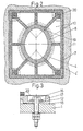
- Figure 1 shows a cooler outlet from a rotary kiln, the kiln having an opening in its shell 1 provided with a support frame which comprises a stub tube 2 and a flange 3 for bolting on of an associated cooler tube (not shown).
- a steel reinforcing ring 4 is provided internally of the stub tube 2, the end of the ring located within the kiln having an integral annular rectangular collar 4' extending generally parallel with the kiln shell 1 and extending radially beyond the join between the stub tube 2 and the kiln shell 1.
- Between the steel ring 4 and the support and kiln shell heat insulating materials are provided in the form of ceramic felt 6, a ceramic body 13 and ceramic ropes 5.
- a ceramic ring 7 is provided along the rim of the collar 4' and underlying the ceramic lining 11 of the kiln.
- the ring 4 and collar 4' are coated internally and on the side facing the kiln respectively with a wear-resisting ceramic material 8 braced to the ring by means of anchoring elements 9.
- a layer 10 of heat- resisting insulating material is inserted between the ceramic material 8, and the ring 4 and collar 4'.
- the ceramic material 8 which constitutes both the lining for the ring 4 and for the collar 4' lies flush with the kiln lining 11.
- the ceramic material 8 is limited by a collar 14 which is attached to the ring 4 or cast integrally with the ring.
- the ceramic material is cast on the steel ring and collar with the insulating layer 10 in such a way that the ring can thereafter be located in the stub tube 2, whereafter the join between the ceramic material 8 and the kiln lining 11 is subsequently formed.
- the collar 4' is provided with bolt holes 12 so that the ring 4 can be firmly attached to the kiln shell 1 at a suitable distance from the join between the kiln shell and the stub tube 2.
- the collar 4' On its underside the collar 4' is provided wioth reinforcing ribs and a reinforcing rim.
- a plastic insulating material is poured into a cavity formed on the underside of the collar situated within the rim.
- the bolt holes 12, as best seen from Figure 3, are situated in a section of the collar 4' which is recessed relative to the rest of the collar in such a way that there is only a small gap between the collar and the kiln shelf at these points.
- This gap is filled with a thin intermediate heat insulating sheet 18 when the collar is secured to the kiln shell 1 by means of a bolt 16 and intermediate disc or washer 17.
- the head of the bolt 16 is located in the recess and is covered with a sheet 20 of ceramic material which in turn is covered by the ceramic lining material which is cast to form the transition between the ceramic material 8 and the kiln lining 11.
- the clearance between the bolt 16 and the bolt hole 12 is sufficiently large to allow for the heat expansion movements of the collar parallel with the kiln shell. Longitudinal expansion of the steel ring will cause the free end of the ring to move, but will not effect the firm abutment of the ceramic material against the collar.
- the ceramic lining 8 has radially extending expansion joints 19 which allow the ceramic material to undergo expansion movements without these movements causing uncontrolled crack formations.
- the insulating layer 10 between the steel ring and the ceramic material 8 can be inserted in sections such that the ceramic material can rest directly against the collar 4' to provide a firm support for the ceramic material to prevent falling clinker from breaking the ceramic material on impact.
- the ring and collar effectively protect and reinforce the join between the kiln shell 1 and stub tube 2 from penetration of destructive hot material. Even if the ceramic lining 8 of the ring 4 is damaged the ring and the insulating material between the ring and the kiln shell and support tube are capable of providing protection for a considerable time thus enabling the kiln to be stopped before serious damage occurs. Surveillance of the temperature of the steel frame can provide an early warning of developing defects.
Description
- The invention relates to rotary kilns having a plurality of outlets for passing material from within the kiln to associated cooler tubes mounted in use in planetary fashion around the outlet end of the kiln. Each kiln outlet has a tubular support to which the inlet end of the associated cooler tube is attached and a steel reinforcing ring within the support, insulation being provided between the ring and the support and the ring being lined internally with a wear-resisting ceramic material. Such a rotary kiln will hereinafter be referred to as "of the kind described".
- It is known to reinforce the outlets of a rotary kiln with a reinforcing frame in the form of a ring or a bush of special steel, in such a way that its axially inner end relative to the kiln is substantially flush with the kiln lining. As the action of the hot clinker within the kiln in use is detrimental to the ring it is normally lined internally with a heat-resistant, wear-resisting material which is cast on the inside of the ring and secured to the ring by suitable bracing elements. The axially inner edge of the ring can also be recessed relative to the kiln lining and coated with a ceramic material flush with the kiln lining.
- As the steel ring and the kiln lining material expand at different rates as a result of the inevitable heat stresses, cracks can form between the ring and kiln lining, which cracks may expose the support to detrimental heat stresses from the hot clinker material. Such crack formations have, according to FR-A-2,404,820, been sought to be avoided by providing a steel ring carrying at its end located within the kiln a braced, integral collar of the same material as the ring the collar extending radially beyond the joint between the support and the kiln shell. However, the steel ring is secured in place at its end within the support and thus longitudinal expansion of the ring caused by heating will cause the cast-on collar to be raised from its position of abutment against the kiln shell so that it can easily be knocked loose when it is hit by clinker being discharged.
- In order to overcome these problems and in accordance with the present invention in a kiln of the kind described the collar is generally parallel to the kiln shell, being insulated from both the support and the kiln shell, being bolted to the kiln shell, and being coated with a wear-resisting ceramic material.
- The ceramic material with which the collar is coated may be flush with the kiln lining and with the lining of the reinforcing ring, and may be formed integrally with the lining of the reinforcing ring.
- Preferably, the annular collar is formed integrally with the ring.
- The ceramic material coating the ring is normally chosen for its wear-resisting capability and therefore its heat conductivity may be considerable. In order to avoid undesirable strong heating of the steel reinforcing ring a layer of insulating material may be provided between the ring and its internal coating of ceramic material.
- To avoid uncontrolled crack formation in the ceramic material when the material and the ring with its collar expand differentially due to heating, radially orientated expansion joints may be provided in the ceramic material.
- One example of a kiln according to the present invention will now be described with reference to the accompanying drawings in which:-
- Figure 1 is a cross-section through a kiln outlet;
- Figure 2 is a section on the line I-I in Figure 1; and,
- Figure 3 shows detail of the method of attachment of the collar to the kiln shell.
- Figure 1 shows a cooler outlet from a rotary kiln, the kiln having an opening in its
shell 1 provided with a support frame which comprises a stub tube 2 and a flange 3 for bolting on of an associated cooler tube (not shown). Asteel reinforcing ring 4 is provided internally of the stub tube 2, the end of the ring located within the kiln having an integral annular rectangular collar 4' extending generally parallel with thekiln shell 1 and extending radially beyond the join between the stub tube 2 and thekiln shell 1. Between thesteel ring 4 and the support and kiln shell heat insulating materials are provided in the form of ceramic felt 6, aceramic body 13 andceramic ropes 5. - In order to prevent any penetration of the material under the collar 4' of the reinforcing
ring 4, aceramic ring 7 is provided along the rim of the collar 4' and underlying theceramic lining 11 of the kiln. Thering 4 and collar 4' are coated internally and on the side facing the kiln respectively with a wear-resistingceramic material 8 braced to the ring by means of anchoringelements 9. To protect thering 4 against the heat conducted through the ceramic material 8 (chosen for its mechanical strength rather than its heat insulation properties) alayer 10 of heat- resisting insulating material is inserted between theceramic material 8, and thering 4 and collar 4'. - In the example shown the
ceramic material 8 which constitutes both the lining for thering 4 and for the collar 4' lies flush with thekiln lining 11. At its outer end theceramic material 8 is limited by a collar 14 which is attached to thering 4 or cast integrally with the ring. To form the kiln outlet the ceramic material is cast on the steel ring and collar with theinsulating layer 10 in such a way that the ring can thereafter be located in the stub tube 2, whereafter the join between theceramic material 8 and thekiln lining 11 is subsequently formed. - From Figure 2 it can be seen that the collar 4' is provided with
bolt holes 12 so that thering 4 can be firmly attached to thekiln shell 1 at a suitable distance from the join between the kiln shell and the stub tube 2. On its underside the collar 4' is provided wioth reinforcing ribs and a reinforcing rim. During the mounting of the steel ring a plastic insulating material is poured into a cavity formed on the underside of the collar situated within the rim. When thering 4 and integral collar 4' are attached to thekiln shell 1, excess plastic material is pressed out from the underside of the collar, after which theceramic ring 7 is positioned. - The
bolt holes 12, as best seen from Figure 3, are situated in a section of the collar 4' which is recessed relative to the rest of the collar in such a way that there is only a small gap between the collar and the kiln shelf at these points. This gap is filled with a thin intermediateheat insulating sheet 18 when the collar is secured to thekiln shell 1 by means of abolt 16 and intermediate disc orwasher 17. The head of thebolt 16 is located in the recess and is covered with asheet 20 of ceramic material which in turn is covered by the ceramic lining material which is cast to form the transition between theceramic material 8 and thekiln lining 11. The clearance between thebolt 16 and thebolt hole 12 is sufficiently large to allow for the heat expansion movements of the collar parallel with the kiln shell. Longitudinal expansion of the steel ring will cause the free end of the ring to move, but will not effect the firm abutment of the ceramic material against the collar. - As shown in Figure 2, the
ceramic lining 8 has radially extendingexpansion joints 19 which allow the ceramic material to undergo expansion movements without these movements causing uncontrolled crack formations. Theinsulating layer 10 between the steel ring and theceramic material 8 can be inserted in sections such that the ceramic material can rest directly against the collar 4' to provide a firm support for the ceramic material to prevent falling clinker from breaking the ceramic material on impact. - The ring and collar effectively protect and reinforce the join between the
kiln shell 1 and stub tube 2 from penetration of destructive hot material. Even if theceramic lining 8 of thering 4 is damaged the ring and the insulating material between the ring and the kiln shell and support tube are capable of providing protection for a considerable time thus enabling the kiln to be stopped before serious damage occurs. Surveillance of the temperature of the steel frame can provide an early warning of developing defects.
Claims (6)
Applications Claiming Priority (2)
| Application Number | Priority Date | Filing Date | Title |
|---|---|---|---|
| GB8000095 | 1980-01-02 | ||
| GB8000095 | 1980-01-02 |
Publications (3)
| Publication Number | Publication Date |
|---|---|
| EP0032010A2 EP0032010A2 (en) | 1981-07-15 |
| EP0032010A3 EP0032010A3 (en) | 1982-01-13 |
| EP0032010B1 true EP0032010B1 (en) | 1984-10-10 |
Family
ID=10510409
Family Applications (1)
| Application Number | Title | Priority Date | Filing Date |
|---|---|---|---|
| EP80304494A Expired EP0032010B1 (en) | 1980-01-02 | 1980-12-12 | Rotary kiln with planetary cooler tube outlets |
Country Status (15)
| Country | Link |
|---|---|
| US (1) | US4353687A (en) |
| EP (1) | EP0032010B1 (en) |
| JP (1) | JPS56119484A (en) |
| KR (1) | KR850001137B1 (en) |
| AU (1) | AU533918B2 (en) |
| BR (1) | BR8008606A (en) |
| CA (1) | CA1146749A (en) |
| DE (1) | DE3069428D1 (en) |
| DK (1) | DK150831B (en) |
| ES (1) | ES498269A0 (en) |
| IE (1) | IE50551B1 (en) |
| IN (1) | IN154653B (en) |
| NO (1) | NO153440C (en) |
| PL (1) | PL133546B1 (en) |
| ZA (1) | ZA807809B (en) |
Families Citing this family (17)
| Publication number | Priority date | Publication date | Assignee | Title |
|---|---|---|---|---|
| FI71837C (en) * | 1982-11-26 | 1987-02-09 | Partek Ab | Cooling design for radiator in rotary kiln. |
| DE4406382C2 (en) * | 1994-02-26 | 1997-08-14 | Metallgesellschaft Ag | Rotary cooler for cooling bulk goods |
| US6444214B1 (en) | 2000-05-04 | 2002-09-03 | Kimberly-Clark Worldwide, Inc. | Ion-sensitive, water-dispersible polymers, a method of making same and items using same |
| US6828014B2 (en) | 2001-03-22 | 2004-12-07 | Kimberly-Clark Worldwide, Inc. | Water-dispersible, cationic polymers, a method of making same and items using same |
| US7772138B2 (en) | 2002-05-21 | 2010-08-10 | Kimberly-Clark Worldwide, Inc. | Ion sensitive, water-dispersible polymers, a method of making same and items using same |
| US6960371B2 (en) | 2002-09-20 | 2005-11-01 | Kimberly-Clark Worldwide, Inc. | Water-dispersible, cationic polymers, a method of making same and items using same |
| US7101456B2 (en) | 2002-09-20 | 2006-09-05 | Kimberly-Clark Worldwide, Inc. | Ion triggerable, cationic polymers, a method of making same and items using same |
| US7157389B2 (en) | 2002-09-20 | 2007-01-02 | Kimberly-Clark Worldwide, Inc. | Ion triggerable, cationic polymers, a method of making same and items using same |
| US6994865B2 (en) | 2002-09-20 | 2006-02-07 | Kimberly-Clark Worldwide, Inc. | Ion triggerable, cationic polymers, a method of making same and items using same |
| US7141519B2 (en) | 2002-09-20 | 2006-11-28 | Kimberly-Clark Worldwide, Inc. | Ion triggerable, cationic polymers, a method of making same and items using same |
| US20060003654A1 (en) * | 2004-06-30 | 2006-01-05 | Lostocco Michael R | Dispersible alcohol/cleaning wipes via topical or wet-end application of acrylamide or vinylamide/amine polymers |
| US8969652B2 (en) | 2010-09-21 | 2015-03-03 | The Procter & Gamble Company | Disposable absorbent article |
| MX345441B (en) | 2010-12-02 | 2017-01-31 | Procter & Gamble | Absorbent article having improved bonding. |
| RU2014114421A (en) | 2011-11-09 | 2015-12-20 | Дзе Проктер Энд Гэмбл Компани | ABSORBENT PRODUCT CONTAINING DOUBLE HEART |
| US10398610B2 (en) | 2014-05-13 | 2019-09-03 | The Procter & Gamble Company | Absorbent article with dual core |
| GB201417386D0 (en) | 2014-10-01 | 2014-11-12 | Nofima As | Sugar-depleted fruit or vegetable juice product, method of producing the same and use thereof to maintain health and treat and to prevent medical ailments |
| US11655572B2 (en) | 2018-12-17 | 2023-05-23 | The Procter & Gamble Company | Method and apparatus for relofting a nonwoven substrate |
Family Cites Families (6)
| Publication number | Priority date | Publication date | Assignee | Title |
|---|---|---|---|---|
| US3396961A (en) * | 1965-08-09 | 1968-08-13 | Gen Refractories Co | Precast taphole assembly |
| FR2212914A5 (en) * | 1973-01-03 | 1974-07-26 | Fives Lille Cail | |
| DE2426546A1 (en) * | 1974-05-31 | 1975-12-11 | Kloeckner Humboldt Deutz Ag | DEVICE FOR GAS-TIGHT CONNECTION OF TWO PIPES WITH EACH OTHER |
| DE2702876C3 (en) * | 1977-01-25 | 1980-07-17 | Krupp Polysius Ag, 4720 Beckum | Rotary kiln with a number of planetary cooling tubes |
| DE2734230C2 (en) * | 1977-07-29 | 1985-05-23 | Klöckner-Humboldt-Deutz AG, 5000 Köln | Outlets of a rotary kiln in satellite cooler tubes |
| FR2404820A1 (en) * | 1977-09-30 | 1979-04-27 | Creusot Loire | Connecting duct joining cement kiln with planetary cooler - consists of metal sleeve with flare, with refractory lining joining sleeve lining to furnace lining |
-
1980
- 1980-12-12 ZA ZA00807809A patent/ZA807809B/en unknown
- 1980-12-12 DE DE8080304494T patent/DE3069428D1/en not_active Expired
- 1980-12-12 AU AU65369/80A patent/AU533918B2/en not_active Ceased
- 1980-12-12 EP EP80304494A patent/EP0032010B1/en not_active Expired
- 1980-12-15 IE IE2630/80A patent/IE50551B1/en unknown
- 1980-12-19 DK DK541780AA patent/DK150831B/en not_active Application Discontinuation
- 1980-12-22 CA CA000367377A patent/CA1146749A/en not_active Expired
- 1980-12-23 NO NO803925A patent/NO153440C/en unknown
- 1980-12-23 JP JP18270680A patent/JPS56119484A/en active Pending
- 1980-12-29 PL PL1980228814A patent/PL133546B1/en unknown
- 1980-12-30 KR KR1019800005028A patent/KR850001137B1/en active IP Right Grant
- 1980-12-30 IN IN1445/CAL/80A patent/IN154653B/en unknown
- 1980-12-30 US US06/221,517 patent/US4353687A/en not_active Expired - Fee Related
- 1980-12-30 BR BR8008606A patent/BR8008606A/en unknown
- 1980-12-31 ES ES498269A patent/ES498269A0/en active Granted
Also Published As
| Publication number | Publication date |
|---|---|
| IE802630L (en) | 1981-07-02 |
| KR830004569A (en) | 1983-07-13 |
| DK150831B (en) | 1987-06-29 |
| CA1146749A (en) | 1983-05-24 |
| IN154653B (en) | 1984-11-24 |
| NO153440B (en) | 1985-12-09 |
| EP0032010A2 (en) | 1981-07-15 |
| PL228814A1 (en) | 1981-09-04 |
| US4353687A (en) | 1982-10-12 |
| EP0032010A3 (en) | 1982-01-13 |
| NO153440C (en) | 1986-03-19 |
| NO803925L (en) | 1981-07-03 |
| DK541780A (en) | 1981-07-03 |
| ES8203146A1 (en) | 1982-02-16 |
| PL133546B1 (en) | 1985-06-29 |
| DE3069428D1 (en) | 1984-11-15 |
| ES498269A0 (en) | 1982-02-16 |
| BR8008606A (en) | 1981-07-28 |
| JPS56119484A (en) | 1981-09-19 |
| AU533918B2 (en) | 1983-12-15 |
| IE50551B1 (en) | 1986-05-14 |
| ZA807809B (en) | 1982-01-27 |
| KR850001137B1 (en) | 1985-08-09 |
| AU6536980A (en) | 1981-07-02 |
Similar Documents
| Publication | Publication Date | Title |
|---|---|---|
| EP0032010B1 (en) | Rotary kiln with planetary cooler tube outlets | |
| US4295825A (en) | System for the protection of the delivery end of a rotary kiln | |
| US4569659A (en) | Refractory lining for a furnace | |
| EP0097482B1 (en) | Refractory coverings for application to fluid conveying members | |
| US5143684A (en) | Insulated roller assembly for a roller furnace | |
| US6132673A (en) | Cooling plates for shaft furnaces | |
| US4570550A (en) | Water cooled door | |
| CA1136073A (en) | Interlocking, truncated triangular insulator | |
| US2731466A (en) | Quench section for carbon black production furnace | |
| FI81079B (en) | FOERFARANDE OCH ANORDNING FOER SMAELTNING AV ETT MEDELST VAERME SMAELTBAR MATERIAL SAOSOM GLASMAENG. | |
| US4508504A (en) | Blast heating apparatus for blast furnaces | |
| US4337735A (en) | Light metal cylinder head for a valve-controlled internal combustion engine | |
| US5865617A (en) | Replaceable nozzle for high temperature reactors having a fire-resistant lining | |
| US4122642A (en) | Refractory liner block | |
| US4886247A (en) | Ceramic brick retainer band for steel ladle | |
| GB1602810A (en) | Rotary kiln having a satellite coder | |
| US4569508A (en) | Metallurgical vessel having an opening and a flange around the opening | |
| US4460335A (en) | System for preventing excess pressure in a gap between a double-shell structure of a blast heating apparatus | |
| RU2210599C2 (en) | Iron making blast furnace and method of its functioning | |
| JPH0247211A (en) | Protecting wall of furnace body in blast furnace | |
| JP3918169B2 (en) | Fireproof segment for shield tunnel | |
| JP2558908Y2 (en) | Immersion tube for vacuum degassing equipment | |
| JPS5937430B2 (en) | rotating drum | |
| JP2005042967A (en) | Heat insulating structure having ceramic fiber and constructing method thereof | |
| JP3613815B2 (en) | Repair method using staves for repairing blast furnace wall |
Legal Events
| Date | Code | Title | Description |
|---|---|---|---|
| PUAI | Public reference made under article 153(3) epc to a published international application that has entered the european phase |
Free format text: ORIGINAL CODE: 0009012 |
|
| AK | Designated contracting states |
Designated state(s): BE DE FR GB IT LU NL SE |
|
| PUAL | Search report despatched |
Free format text: ORIGINAL CODE: 0009013 |
|
| AK | Designated contracting states |
Designated state(s): BE DE FR GB IT LU NL SE |
|
| 17P | Request for examination filed |
Effective date: 19820514 |
|
| ITF | It: translation for a ep patent filed |
Owner name: DR. ING. A. RACHELI & C. |
|
| GRAA | (expected) grant |
Free format text: ORIGINAL CODE: 0009210 |
|
| AK | Designated contracting states |
Designated state(s): BE DE FR GB IT LU NL SE |
|
| PG25 | Lapsed in a contracting state [announced via postgrant information from national office to epo] |
Ref country code: NL Effective date: 19841010 |
|
| REF | Corresponds to: |
Ref document number: 3069428 Country of ref document: DE Date of ref document: 19841115 |
|
| ET | Fr: translation filed | ||
| PGFP | Annual fee paid to national office [announced via postgrant information from national office to epo] |
Ref country code: FR Payment date: 19841207 Year of fee payment: 5 |
|
| PGFP | Annual fee paid to national office [announced via postgrant information from national office to epo] |
Ref country code: DE Payment date: 19841215 Year of fee payment: 5 |
|
| PG25 | Lapsed in a contracting state [announced via postgrant information from national office to epo] |
Ref country code: LU Free format text: LAPSE BECAUSE OF NON-PAYMENT OF DUE FEES Effective date: 19841231 |
|
| PGFP | Annual fee paid to national office [announced via postgrant information from national office to epo] |
Ref country code: SE Payment date: 19841231 Year of fee payment: 5 Ref country code: BE Payment date: 19841231 Year of fee payment: 5 |
|
| NLV1 | Nl: lapsed or annulled due to failure to fulfill the requirements of art. 29p and 29m of the patents act | ||
| PLBE | No opposition filed within time limit |
Free format text: ORIGINAL CODE: 0009261 |
|
| STAA | Information on the status of an ep patent application or granted ep patent |
Free format text: STATUS: NO OPPOSITION FILED WITHIN TIME LIMIT |
|
| 26N | No opposition filed | ||
| BERE | Be: lapsed |
Owner name: F.L. SMIDTH & CO. A/S Effective date: 19861231 |
|
| PG25 | Lapsed in a contracting state [announced via postgrant information from national office to epo] |
Ref country code: SE Effective date: 19871213 |
|
| PG25 | Lapsed in a contracting state [announced via postgrant information from national office to epo] |
Ref country code: BE Effective date: 19871231 |
|
| BERE | Be: lapsed |
Owner name: F.L. SMIDTH & CO. A/S Effective date: 19871231 |
|
| GBPC | Gb: european patent ceased through non-payment of renewal fee | ||
| PG25 | Lapsed in a contracting state [announced via postgrant information from national office to epo] |
Ref country code: FR Free format text: LAPSE BECAUSE OF NON-PAYMENT OF DUE FEES Effective date: 19880831 |
|
| PG25 | Lapsed in a contracting state [announced via postgrant information from national office to epo] |
Ref country code: DE Effective date: 19880901 |
|
| REG | Reference to a national code |
Ref country code: FR Ref legal event code: ST |
|
| PG25 | Lapsed in a contracting state [announced via postgrant information from national office to epo] |
Ref country code: GB Free format text: LAPSE BECAUSE OF NON-PAYMENT OF DUE FEES Effective date: 19881118 |
|
| EUG | Se: european patent has lapsed |
Ref document number: 80304494.0 Effective date: 19880912 |