EP0032002B1 - Vorrichtung zum Nachführen eines Sonnenkollektors nach dem Sonnenstand - Google Patents
Vorrichtung zum Nachführen eines Sonnenkollektors nach dem Sonnenstand Download PDFInfo
- Publication number
- EP0032002B1 EP0032002B1 EP80304404A EP80304404A EP0032002B1 EP 0032002 B1 EP0032002 B1 EP 0032002B1 EP 80304404 A EP80304404 A EP 80304404A EP 80304404 A EP80304404 A EP 80304404A EP 0032002 B1 EP0032002 B1 EP 0032002B1
- Authority
- EP
- European Patent Office
- Prior art keywords
- reflector
- sunlight
- optical axis
- pair
- vertical
- Prior art date
- Legal status (The legal status is an assumption and is not a legal conclusion. Google has not performed a legal analysis and makes no representation as to the accuracy of the status listed.)
- Expired
Links
- 230000003287 optical effect Effects 0.000 claims description 42
- 238000009792 diffusion process Methods 0.000 claims description 8
- 241000251468 Actinopterygii Species 0.000 claims description 5
- 239000000835 fiber Substances 0.000 claims description 5
- 238000010348 incorporation Methods 0.000 claims description 2
- 239000007788 liquid Substances 0.000 description 20
- 239000011521 glass Substances 0.000 description 14
- 238000004891 communication Methods 0.000 description 4
- 230000007423 decrease Effects 0.000 description 3
- 230000002265 prevention Effects 0.000 description 3
- 238000001816 cooling Methods 0.000 description 2
- 238000010586 diagram Methods 0.000 description 2
- 238000010438 heat treatment Methods 0.000 description 2
- 230000002093 peripheral effect Effects 0.000 description 2
- 238000007789 sealing Methods 0.000 description 2
- 230000015572 biosynthetic process Effects 0.000 description 1
- 238000006243 chemical reaction Methods 0.000 description 1
- 230000005494 condensation Effects 0.000 description 1
- 238000009833 condensation Methods 0.000 description 1
- 238000010276 construction Methods 0.000 description 1
- 230000003247 decreasing effect Effects 0.000 description 1
- 238000001514 detection method Methods 0.000 description 1
- 238000006073 displacement reaction Methods 0.000 description 1
- 238000005286 illumination Methods 0.000 description 1
- 239000000463 material Substances 0.000 description 1
- 239000002184 metal Substances 0.000 description 1
- NJPPVKZQTLUDBO-UHFFFAOYSA-N novaluron Chemical compound C1=C(Cl)C(OC(F)(F)C(OC(F)(F)F)F)=CC=C1NC(=O)NC(=O)C1=C(F)C=CC=C1F NJPPVKZQTLUDBO-UHFFFAOYSA-N 0.000 description 1
- 239000013307 optical fiber Substances 0.000 description 1
- 238000005192 partition Methods 0.000 description 1
- 238000011160 research Methods 0.000 description 1
- 230000000699 topical effect Effects 0.000 description 1
Images

Classifications
-
- G—PHYSICS
- G01—MEASURING; TESTING
- G01S—RADIO DIRECTION-FINDING; RADIO NAVIGATION; DETERMINING DISTANCE OR VELOCITY BY USE OF RADIO WAVES; LOCATING OR PRESENCE-DETECTING BY USE OF THE REFLECTION OR RERADIATION OF RADIO WAVES; ANALOGOUS ARRANGEMENTS USING OTHER WAVES
- G01S3/00—Direction-finders for determining the direction from which infrasonic, sonic, ultrasonic, or electromagnetic waves, or particle emission, not having a directional significance, are being received
- G01S3/78—Direction-finders for determining the direction from which infrasonic, sonic, ultrasonic, or electromagnetic waves, or particle emission, not having a directional significance, are being received using electromagnetic waves other than radio waves
- G01S3/782—Systems for determining direction or deviation from predetermined direction
- G01S3/785—Systems for determining direction or deviation from predetermined direction using adjustment of orientation of directivity characteristics of a detector or detector system to give a desired condition of signal derived from that detector or detector system
- G01S3/786—Systems for determining direction or deviation from predetermined direction using adjustment of orientation of directivity characteristics of a detector or detector system to give a desired condition of signal derived from that detector or detector system the desired condition being maintained automatically
- G01S3/7861—Solar tracking systems
-
- F—MECHANICAL ENGINEERING; LIGHTING; HEATING; WEAPONS; BLASTING
- F24—HEATING; RANGES; VENTILATING
- F24S—SOLAR HEAT COLLECTORS; SOLAR HEAT SYSTEMS
- F24S50/00—Arrangements for controlling solar heat collectors
- F24S50/20—Arrangements for controlling solar heat collectors for tracking
-
- Y—GENERAL TAGGING OF NEW TECHNOLOGICAL DEVELOPMENTS; GENERAL TAGGING OF CROSS-SECTIONAL TECHNOLOGIES SPANNING OVER SEVERAL SECTIONS OF THE IPC; TECHNICAL SUBJECTS COVERED BY FORMER USPC CROSS-REFERENCE ART COLLECTIONS [XRACs] AND DIGESTS
- Y02—TECHNOLOGIES OR APPLICATIONS FOR MITIGATION OR ADAPTATION AGAINST CLIMATE CHANGE
- Y02E—REDUCTION OF GREENHOUSE GAS [GHG] EMISSIONS, RELATED TO ENERGY GENERATION, TRANSMISSION OR DISTRIBUTION
- Y02E10/00—Energy generation through renewable energy sources
- Y02E10/40—Solar thermal energy, e.g. solar towers
- Y02E10/47—Mountings or tracking
Definitions
- This invention relates to a sun following-up device for use with a solar heat utilization apparatus which is adapted to focus received sunlight and to utilize the focused sunlight as heat energy for heating and cooling purposes.
- the Applicant has developed a solar heat utilization apparatus which is adapted to condense received sunlight and then to convert the condensed sunlight into heat energy, and which utilizes a light to energy conversion device having a small area and which can be produced at little expense.
- the solar heat utilization apparatus is disclosed in European Patent Application No. 80100951.5 (EP-A-15 487) filed in the name of the present Applicant.
- the solar heat utilization apparatus referred to above is a so-called sunlight reflection apparatus of the two shaft sunlight following-up type and one of the most important requirements of the apparatus is that the focused sunlight accurately impinges on the heat collecting means which is provided at the focus of the parabolic trough of a sunlight reflector.
- the centre angle of the sunlight reflector is 213°
- the angular deviation is ⁇ 1 °5' for a sunlight condensing magnification of 27 times and +33' for a sunlight condensing magnification of 54 times.
- the angle of the vertical rotary shaft is especially required to be precise, although if the angle of the horizontal rotary shafts is not very precise, a slight deviation of the angle of the horizontal rotary shafts will not present any serious problem if the length of the heat collecting means is extended by a small amount.
- the optical axis of the reflector is reorientated vertically so as to minimize the area of the reflector parabolic trough which faces the wind.
- the reflector is allowed to rotate freely under the force of the wind and the reflector is returned to the normal position when the wind velocity decreases. It is also required that the reflector returns automatically to the normal position from the position which the reflector assumed at the time of interruption of electric current supply or at night.
- said device comprises a fish eye lens unit intended to be mounted with its optical axis parallel to the optical axis of the solar energy collector, an optical system associated with said lens unit and arranged to form an image at a focal plane, a pair of spaced diffusing screens located at said focal plane and arranged to define a slit between them, and said first pair of photosensitive cells are respectively associated with said diffusing screens for receiving light therefrom, a pair of fiber optic means respectively having one end thereof located within said slit at locations spaced apart to leave a clearance therebetween, and said second pair of photosensitive cells are associated with the other ends of said fiber optic means to receive light therefrom.
- Another aspect of the present invention provides a sun following-up device for a solar heat collector, in which when the time period during which the quantity of the sunlight is less than a predetermined value is longer than a predetermined time period and/or the wind velocity is in excess of a predetermined value, the optical axis of a reflector of the solar collector is orientated vertically and the reflector is maintained in the position in which the optical axis is orientated vertically for a predetermined time period after the setting of the optical axis to the vertical.
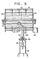
- the solar heat utilization apparatus generally comprises a sunlight reflector having a parabolic trough, a hollow vertical rotary shaft extending vertically through the centre of the reflector, a pair of horizontal rotary shafts rotatably supporting the reflector, a heat collecting means provided at the focus of the parabolic trough of the sunlight reflector and a liquid circulating pipe connected to and extending in parallel to the heat collecting means.
- the circulating pipe has, on opposite sides thereof in coaxial relationship to the horizontal rotary shafts, an inlet tube an an outlet tube for liquid to be heated.
- the sunlight reflector 17 is formed by a pair of metal plates 19, 19' secured to a grid structure framework 18 which is concave on the upper surface so as to define the parabolic trough of the sunlight reflector 17, and the heat collecting means 20 is provided at the focus of the reflector.
- the liquid circulating pipe 21 is connected to and in communication with the heat collecting means 20 and liquid to be heated flows from the pipe 21 into the heat collecting means 20 where the liquid is heated with the heat from the sunlight and the heated liquid flows from the heat collecting means 20 back into the pipe 21.
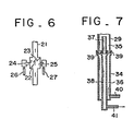
- a mechanism for the prevention of cold liquid discharge which comprises a partition plate or buffer 22 and a check valve 23 (see Figure 6).
- An inlet tube 24 and an outlet tube 25 for liquid to be heated are provided on the opposite sides of the pipe 21 in parallel to and in communication with the pipe 21.
- the inlet tube 24 has a liquid supply tube 26 connected thereto and the outlet tube 25 has a liquid discharge tube 27 connected thereto, respectively.
- the supply tube 26 and discharge tube 27 are connected to a common double tube 29 which is in turn disposed coaxially within the hollow vertical rotary shaft 28 for rotation together with the latter.
- a pair of opposite shaft support members 31 are provided in diametrically opposite positions of the framework 18 to support rotatably the inner ends of a pair of horizontal rotary stub shafts 30 and the other or outer ends of the stub shafts are journalled in bearings 33 which are in turn suitably supported by the free ends of the opposite legs of a U-shaped frame member 32 secured to the vertical hollow shaft 28.
- the horizontal rotary stub shafts 30 are disposed coaxial or substantially coaxial with the liquid inlet and outlet tubes 24, 25.
- the double tube 29 is connected at the lower end to a hollow stationary shaft 34 which is also in the form of a double tube.
- the outer tube 35 of the double tube 29 is in communication with the outer tube 36 of the stationary shaft 34 to provide a supply passage for liquid to be heated.
- the inner tube 37 of the double tube 29 is in communication with the inner tube 38 of the stationary shaft 34 to provide a discharge passage for the liquid after the liquid has been heated.
- the sealing between the outer tubes 35, 36 of the double tube and stationary shaft 29, 34 and between the inner tubes 37, 38 of the double tube and stationary shafts, respectively is not required to be closely tight, but may be just sufficient to prevent leakage of the liquid to the exterior of the system.
- the sealing between the double tube 29 and stationary shaft 34 is effected by the employment of O-rings 39.
- the outer tube 36 of the stationary shaft 34 is connected at the lower end to a supply tube 40 for liquid to be heated and the inner tube 38 of the stationary shaft is connected at the lower end to a discharge tube 41 for heated liquid, respectively.
- the liquid from the supply tube 40 associated with the stationary shaft 34 passes through the supply passage defined by the outer tubes 35, 36 of the double tube 29 and stationary shaft 34 to and through the supply tube 26 of the pipe 21 connected to the outer tube 35 of the double tube 29.
- the heated liquid discharged from the pipe 21 flows through the discharge tube 27 into the discharge passage defined by the inner tubes 37, 38 of the double tube 29 and stationary shaft 34 and then into the discharge tube 41 associated with the inner tube 38 of the stationary shaft to be discharged out of the system.
- a rudder 42 is attached to the framework 18 and a gear 43 is mounted at the outer end of one of the horizontal rotary shafts 30 (the lefthand shaft as seen in Figure 4) which is operatively connected to a drive means such as a motor for driving the particular stub shaft 30.
- a gear is mounted on a pipe 47 secured to the vertical rotary shaft 28 and meshes a smaller diameter gear 45 which is in turn operatively connected to a drive means 46 such as a clutch type drive means for rotating the vertical rotary shaft 28.
- the drive means 46 is mounted on a pedestal 48 which is held in position on a suitable support base such as a floor.
- Reference numeral 49 denotes support rods extending between and secured at the opposite ends to the heat collecting means 20 and framework 18.
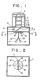
- FIGS 1 to 3 inclusive show the preferred embodiment of sun following-up device of the present invention which is to be incorporated in the solar heat utilization apparatus referred to hereinabove.
- the sun following-up device is positioned between one of the shorter support rods 49 and the double tube 29 in coaxial relationship to the optical axis of the reflector 17 and adapted to follow up- the moving sun.
- the sun following-up device will be now described in detail referring to Figures 1 to 3 inclusive.
- reference numerals 1 and 1' denote fish eye lenses laid one upon another on the top of a hollow cylindrical member 2 and having the field of view of 180° which covers the entire range of angles of incidence of sunlight when the optical axis of the sunlight reflector 17 is disposed vertically.
- the incoming light is refracted by the fish eye lenses 1, 1' and reaches a condensing lens 3 positioned immediately below the lower concavo- convex lens 1' within the cylindrical member 2.
- the light is further refracted by the condensing lens 3 and passes through a filter 4 positioned below and spaced from the focusing lens 3 within the cylindrical member 2 to adjust the intensity of the light.
- the light passes through an image formation adjusting lens 5 positioned below and spaced from the filter 4 within the cylindrical member 2 and then through a semi-transparent mirror 6, provided at the lower end of the cylindrical member 2, to a screen glass 8, provided within a casing 7 positioned under the cylindrical member 2, and forms an image on the: screen glass 8.
- Diffusion glasses 9, 9' are provided on the undersurface of the screen glass 8 in the centre thereof in opposed and spaced relationship to provide a clearance or slit 11 between the opposing faces of the glasses 9, 9' for the purpose to be described hereinafter. Having passed through the screen glass 8, the light is diffused by either the diffusion glass 9 or 9' and strikes on either one of photosensitive cells 10 and 10' provided on the undersurface of the diffusion glasses 9, 9', respectively.
- the peripheries of the diffusion glasses 9, 9' are preferably coated with a reflective material which reflects the light into the interior of the diffusion glasses.
- each of the photosensitive cells 10, 10' senses the light regardless of the position within the area of the associated diffusion glass 9 or 9' at which the light impinges, the size of each of the photosensitive cells 10, 10' is not required to be sufficient to cover the entire image forming area, and the photosensitive cells 10, 10' may thus be of small size. Furthermore, each of the photosensitive cells may be formed by a single element.
- the photosensitive cell 10 is designed to operate a switch which is adapted to rotate the vertical rotary shaft 28 in the clockwise direction as seen from above in Figure 4 whereas the photosensitive cell 10' is adapted to operate a switch which is adapted to rotate the vertical rotary shaft 28 in the counter-clockwise direction as seen from above in Figure 4.
- the width of the slit 11 defined between the diffusion glasses 9, 9' is of such an extent that the angular deviation of the optical axis of the reflector 17 with respect to the optical axis of the sunlight can be maintained within a suitable range ( ⁇ 1 °, for example), and thus, the control electric circuit is so arranged that so long as the formed image is positioned within the slit 11, the vertical rotary shaft 28 remains stationary and on the other hand, if and when the formed image displaces from the slit 11, the photosensitive cell 10 or 10' senses such displacement and rotates the motor for the rotary shaft 28 whereby the formed image always enters the slit 11 and remains there.
- the motor ceases its rotation when the angular deviation of the optical axis of the reflector 17 with respect to the optical axis of the sunlight is maintained within a suitable range ( ⁇ 1 °, for example).
- the solar heat utilization apparatus also ceases its rotation.
- the filter 4 Since the intensity of the sunlight on the image forming surface of the screen glass 8 varies depending upon the magnitude of the angular deviation of the optical axis of the reflector with respect to that of the sunlight, it is desirable to design the filter 4 so that the light amount is increased in the central area of the filter and decreased in the peripheral area thereof whereby the intensity of illumination of the image formed on the screen glass 8 is made substantially the same throughout the image.
- optical sensors comprising optical fibers 13, 13', ends of which are inserted in the slit 11 so as to leave a clearance 12, which may be a suitable shape such as square or circular, between the ends of the optical fibres 13, 13', and photosensitive cells 14, 14' secured to the other ends of the optical fibres 13, 13', respectively.
- the motor 44 When the formed image is positioned on the photosensitive cell 14, the motor 44 is actuated to rotate the horizontal shafts 30 so as to increase the angle of elevation of the reflector optical axis.
- the motor 44 is actuated so as to decrease the angle of elevation of the reflector optical axis.
- reference numeral 15 denotes a light quantity detecting photosensitive sensor and reference numeral 16 denotes a condensing lens.
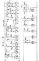
- FIG 3 is a diagram showing the control sequence of the system and in Figure 3, with a DC voltage applied to the lines P and Q and an AC voltage applied to the lines u and v, when the photosensitive sensor D (corresponding to the photosensitive sensor 15 in Figure 1) is actuated, the relay R 4 operates momentarily and the relay R 5 then operates and maintains the operation condition.
- the relay contact R 5a3 turns on the control circuit for the vertical rotary shaft drive motor M-Y and the horizontal rotary shaft drive motor M-X, the control circuit comprising relays R 7 ⁇ R 12 and a timer TM 4'
- the circuit of the photosensitive cell 10 includes the relay R 9 and the circuit of the photosensitive cell 10' includes the relay R 10 .
- the circuit of the photosensitive cell 14 includes the relay R 11 and the circuit of the photosensitive cell 14' includes the relay R, 2 . These circuits of the photosensitive cells 14, 14' are similarly interlocked at the contact b.
- operation of the timer TM 3 is initiated. If the photosensitive sensor D turns on again before the time set for the timer TM 3 elapses, the timer TM 3 is reset. When the time set for the timer TM 3 elapses, the relay R 6 is operated and maintains its operative condition and the relay R 5 is reset.
- the horizontal rotary shaft drive motor M-X rotates in the forward direction to increase the angle of elevation of the reflector until the angle reaches the vertical whereupon a sensor C which is adapted to detect the angle of elevation is operated to reset the relay R s .
- the magnet plunger MGP, for the vertical rotary shaft clutch is declutched by the AND circuit of the relays R 32 and R, and the vertical rotary shaft is mechanically released.
- the relay contacts R lb2 and R lb3 are interlocked for the sake of safety and the relay R 3 and timer TM 2 serve for resetting the circuit.
- the magnet plunger MGP for the vertical rotary shaft clutch is declutched and at the same time, the magnet plunger MGP 2 for the horizontal rotary shaft clutch is also declutched to cope with high wind under con-. ditions of electric current supply interruption.
- a reverse direction rotation prevention circuit is provided and the circuit comprises a limit switch B for controlling the angle of elevation of the reflector, a relay R 7 , a relay R a and a timer TM 4 .
- the optical axis of the reflector is maintained vertical and the vertical rotary shaft is left to rotate freely so as to present a minimum area of the reflector in the direction of the wind to thereby allow the reflector to rotate freely and thus, when the velocity of the wind drops to a value below 10 m/sec, the reflector may assume an unexpected orientation with respect to the topical axis of the sunlight.
- the single sun following-up device can cope with various different weather conditions, when the time period during which the light quantity is less than a predetermined value, because the sun sets or is hidden behind a cloud, extends beyond a predetermined time length, such as 30 minutes, and/or the wind velocity exceeds a predetermined value such as 10 m/sec, for example, the horizontal rotary shafts are rotated so as to orientate the optical axis of the reflector vertically and only when the wind velocity exceeds the predetermined value referred to above is the electromagnet clutch for the vertical rotary shaft disengaged to allow the shaft to rotate freely.
- the optical axis of the reflector is maintained vertical by holding the reflector in position by the use of a suitable means such as a spring.
- limit switches are provided on the framework in a position slightly beyond the vertical of the optical axis of the reflector and in a position at the angle of about 5° beyond the horizon of the reflector optical axis, respectively.
Landscapes
- Engineering & Computer Science (AREA)
- Physics & Mathematics (AREA)
- Sustainable Development (AREA)
- Life Sciences & Earth Sciences (AREA)
- Sustainable Energy (AREA)
- General Physics & Mathematics (AREA)
- Radar, Positioning & Navigation (AREA)
- Remote Sensing (AREA)
- Electromagnetism (AREA)
- Thermal Sciences (AREA)
- Chemical & Material Sciences (AREA)
- Combustion & Propulsion (AREA)
- Mechanical Engineering (AREA)
- General Engineering & Computer Science (AREA)
- Control Of Position Or Direction (AREA)
- Photovoltaic Devices (AREA)
Claims (7)
Applications Claiming Priority (2)
| Application Number | Priority Date | Filing Date | Title |
|---|---|---|---|
| JP15818379A JPS5691151A (en) | 1979-12-07 | 1979-12-07 | Sun tracking device of solar ray reflector mirror |
| JP158183/79 | 1979-12-07 |
Publications (3)
| Publication Number | Publication Date |
|---|---|
| EP0032002A2 EP0032002A2 (de) | 1981-07-15 |
| EP0032002A3 EP0032002A3 (en) | 1981-10-28 |
| EP0032002B1 true EP0032002B1 (de) | 1984-02-01 |
Family
ID=15666075
Family Applications (1)
| Application Number | Title | Priority Date | Filing Date |
|---|---|---|---|
| EP80304404A Expired EP0032002B1 (de) | 1979-12-07 | 1980-12-05 | Vorrichtung zum Nachführen eines Sonnenkollektors nach dem Sonnenstand |
Country Status (5)
| Country | Link |
|---|---|
| US (1) | US4362931A (de) |
| EP (1) | EP0032002B1 (de) |
| JP (1) | JPS5691151A (de) |
| AU (1) | AU540677B2 (de) |
| DE (1) | DE3066439D1 (de) |
Families Citing this family (33)
| Publication number | Priority date | Publication date | Assignee | Title |
|---|---|---|---|---|
| JPS597328A (ja) * | 1982-07-05 | 1984-01-14 | Takashi Mori | 太陽光収集装置 |
| US4982723A (en) * | 1982-11-10 | 1991-01-08 | Kei Mori | Accumulator arrangement for the sunlight energy |
| US4747664A (en) * | 1985-04-29 | 1988-05-31 | Slaughter Harold W | Rotary reflective marker |
| JPS6251407U (de) * | 1985-09-17 | 1987-03-31 | ||
| EP0278181A3 (de) * | 1987-02-06 | 1990-07-04 | Varo, Inc. | Strahlungsenergieempfänger mit streuender Oberfläche |
| US4835381A (en) * | 1987-10-30 | 1989-05-30 | Varo, Inc. | Wide field of view radiant energy receiver |
| DE3922153A1 (de) * | 1989-07-06 | 1991-01-17 | Hella Kg Hueck & Co | Optischer sensor |
| US5079414A (en) * | 1990-10-09 | 1992-01-07 | Gte Government Systems Corporation | Tracking telescope using an atomic resonance filter |
| DE4446303C2 (de) * | 1994-12-23 | 1997-01-23 | Deutsche Forsch Luft Raumfahrt | Vorrichtung zum Konzentrieren von Solarstrahlung |
| US6005249A (en) * | 1997-03-18 | 1999-12-21 | Smithsonian Environmental Research Center | Cosine corrected optical pathway of a spectral radiometer |
| JP4122701B2 (ja) * | 2000-10-24 | 2008-07-23 | 株式会社デンソー | 日射センサ |
| KR20030015969A (ko) * | 2001-08-18 | 2003-02-26 | 권현옥 | 태양열 에너지를 이용한 아파트 |
| US6662801B2 (en) * | 2001-10-02 | 2003-12-16 | Pinnacle West Capital Corporation | Celestial tracking apparatus and method of controlling wind stow therefor |
| SE0301857D0 (sv) * | 2003-06-24 | 2003-06-24 | Uab Accel Elektronika | An optical radiation intensity sensor |
| KR100661046B1 (ko) | 2004-11-10 | 2006-12-26 | 이상종 | 태양광 이용 전기 및 온수 생성 시스템 |
| EP1901012B1 (de) * | 2005-06-09 | 2014-02-12 | Chengwei Wang | Lichtnachführsensor und sonnenlichtnachführsystem dafür |
| RU2417388C2 (ru) * | 2006-11-24 | 2011-04-27 | Учреждение Российской академии наук Институт кристаллографии имени А.В.Шубникова РАН | Солнечно-слепой объектив |
| US20080258051A1 (en) * | 2007-04-11 | 2008-10-23 | Solfocus, Inc. | Equipment and Process for Measuring the Precision of Sun Tracking for Photovoltaic Concentrators |
| US7665459B2 (en) * | 2007-04-18 | 2010-02-23 | Energistic Systems, Llc | Enclosed solar collector |
| CN101515061B (zh) * | 2008-02-19 | 2010-10-13 | 台湾基材科技股份有限公司 | 具有滤光透镜的集光装置 |
| GB2458639B (en) * | 2008-03-25 | 2012-03-14 | Roy Trevor Ince | Solar alignment device |
| US7779829B2 (en) * | 2008-03-31 | 2010-08-24 | Solfocus, Inc. | Solar thermal collector manifold |
| JP5086909B2 (ja) * | 2008-06-17 | 2012-11-28 | ルネサスエレクトロニクス株式会社 | 電源回路、及びその制御方法 |
| US8210162B2 (en) | 2009-05-04 | 2012-07-03 | Douglas Evan Simmers | Tracking device with weathervaning wind stowage mode of operation |
| DE102010001867A1 (de) * | 2010-02-12 | 2011-08-18 | ZF Friedrichshafen AG, 88046 | Vorrichtung zur Ermittlung einer Position einer Lichtquelle |
| CN102854893A (zh) * | 2011-06-28 | 2013-01-02 | 吴昌德 | 一种追踪太阳光照射方向的装置 |
| CN102854896A (zh) * | 2011-06-28 | 2013-01-02 | 吴昌德 | 一种追踪太阳光照射方向的方法 |
| CN102854889A (zh) * | 2011-06-28 | 2013-01-02 | 吴昌德 | 用光伏电池追踪太阳光照射方向的方法 |
| ITRM20110455A1 (it) * | 2011-09-02 | 2013-03-03 | Fabrizio Liberati | Sensore per rilevare il disallineamento di un pannello fotovoltaico rispetto al sole. |
| CN104020783B (zh) * | 2014-05-15 | 2016-11-02 | 南京工程学院 | 一种采用高精度太阳能跟踪控制器的碟式聚光系统 |
| CN105259930B (zh) * | 2015-11-25 | 2018-02-23 | 佛山科学技术学院 | 全天候太阳方位跟踪方法及装置 |
| CN106873643B (zh) * | 2017-04-06 | 2020-07-31 | 江苏大学 | 一种用于太阳跟踪的光纤式光电传感器 |
| CN107153426B (zh) * | 2017-05-26 | 2020-06-26 | 江苏大学 | 一种基于光纤导光的太阳跟踪传感器 |
Family Cites Families (10)
| Publication number | Priority date | Publication date | Assignee | Title |
|---|---|---|---|---|
| US3917942A (en) * | 1974-09-23 | 1975-11-04 | Brown Manufacturing Company | Sun tracking control apparatus |
| JPS522454A (en) * | 1975-06-24 | 1977-01-10 | Nippon Buroa Kk | Apparatus for following sun |
| US4324225A (en) * | 1975-07-11 | 1982-04-13 | Trihey John M | Solar tracking device |
| JPS5275451A (en) * | 1975-12-19 | 1977-06-24 | Mitsubishi Electric Corp | Device for tracking sun in vertically condensing type heliostat type s olar furnace |
| US4100915A (en) * | 1977-02-18 | 1978-07-18 | Ingemar Carlson | Solar energy heating apparatus |
| JPS5420438A (en) * | 1977-07-18 | 1979-02-15 | Teruie Fujiwara | Apparatus for following sunshine |
| US4153038A (en) * | 1977-08-15 | 1979-05-08 | Mcdonald Bernard | Solar energy collecting system |
| US4146785A (en) * | 1978-02-13 | 1979-03-27 | Sunpower Systems Corporation | Sun-tracking control system for solar collector |
| IT1103059B (it) * | 1978-09-01 | 1985-10-14 | Gori & Zucchi Spa | Sistema inseguitore solare o di al tra sorgente di luce con ricerca automatica della massima irradiazione |
| JPS55116052A (en) * | 1979-02-27 | 1980-09-06 | Nippon Chem Plant Consultant:Kk | Solar-heat utilizing device |
-
1979
- 1979-12-07 JP JP15818379A patent/JPS5691151A/ja active Granted
-
1980
- 1980-12-04 US US06/213,120 patent/US4362931A/en not_active Expired - Lifetime
- 1980-12-05 AU AU65109/80A patent/AU540677B2/en not_active Ceased
- 1980-12-05 DE DE8080304404T patent/DE3066439D1/de not_active Expired
- 1980-12-05 EP EP80304404A patent/EP0032002B1/de not_active Expired
Also Published As
| Publication number | Publication date |
|---|---|
| EP0032002A2 (de) | 1981-07-15 |
| EP0032002A3 (en) | 1981-10-28 |
| AU540677B2 (en) | 1984-11-29 |
| JPS5723874B2 (de) | 1982-05-20 |
| JPS5691151A (en) | 1981-07-23 |
| US4362931A (en) | 1982-12-07 |
| DE3066439D1 (en) | 1984-03-08 |
| AU6510980A (en) | 1981-06-18 |
Similar Documents
| Publication | Publication Date | Title |
|---|---|---|
| EP0032002B1 (de) | Vorrichtung zum Nachführen eines Sonnenkollektors nach dem Sonnenstand | |
| US4439020A (en) | Sunrays focusing apparatus | |
| US4243018A (en) | Solar energy concentrator | |
| US4628142A (en) | Solar tracking mechanisms | |
| US3861379A (en) | Low profile solar ray concentrator | |
| US4649899A (en) | Solar tracker | |
| CN100582820C (zh) | 一种反射镜及采用该反射镜的太阳能槽式集热器 | |
| US4090498A (en) | Solar heater | |
| EP0729557A1 (de) | Anlage zum sammeln von strahlungsenergie | |
| US4245153A (en) | Sun tracking system for solar collector | |
| NL1031544C2 (nl) | Inrichting voor het omzetten van zonne-energie. | |
| US5203318A (en) | Sun tracking solar concentrator | |
| US4498456A (en) | Self-tracking mechanisms for solar collectors | |
| US4061130A (en) | Solar energy device | |
| WO2002001117A1 (fr) | Reflecteur de rayonnement solaire et systeme a energie solaire comprenant ledit reflecteur | |
| CN101881520A (zh) | 一种自动跟踪线聚焦太阳能集热管接收吊架装置 | |
| CN108981190A (zh) | 一种全方位跟踪抛物面镜热能吸收系统 | |
| KR102821249B1 (ko) | 반사패널 태양광 집광장치 | |
| JPH02122159A (ja) | 太陽光集光装置および太陽光端末投光装置 | |
| CN2478035Y (zh) | 太阳光收集装置 | |
| JPH0338591Y2 (de) | ||
| JPS6073248A (ja) | 太陽位置追従装置 | |
| JP3498294B2 (ja) | 太陽光の自動追尾採光装置 | |
| JPH0810291B2 (ja) | 太陽光採光システム | |
| CN86201577U (zh) | 太阳能定向跟踪装置 |
Legal Events
| Date | Code | Title | Description |
|---|---|---|---|
| PUAI | Public reference made under article 153(3) epc to a published international application that has entered the european phase |
Free format text: ORIGINAL CODE: 0009012 |
|
| AK | Designated contracting states |
Designated state(s): DE FR GB IT NL |
|
| PUAL | Search report despatched |
Free format text: ORIGINAL CODE: 0009013 |
|
| RBV | Designated contracting states (corrected) |
Designated state(s): DE FR GB IT NL |
|
| AK | Designated contracting states |
Designated state(s): DE FR GB IT NL |
|
| 17P | Request for examination filed |
Effective date: 19820415 |
|
| ITF | It: translation for a ep patent filed | ||
| GRAA | (expected) grant |
Free format text: ORIGINAL CODE: 0009210 |
|
| AK | Designated contracting states |
Designated state(s): DE FR GB IT NL |
|
| REF | Corresponds to: |
Ref document number: 3066439 Country of ref document: DE Date of ref document: 19840308 |
|
| ET | Fr: translation filed | ||
| PGFP | Annual fee paid to national office [announced via postgrant information from national office to epo] |
Ref country code: FR Payment date: 19841030 Year of fee payment: 5 |
|
| PLBE | No opposition filed within time limit |
Free format text: ORIGINAL CODE: 0009261 |
|
| STAA | Information on the status of an ep patent application or granted ep patent |
Free format text: STATUS: NO OPPOSITION FILED WITHIN TIME LIMIT |
|
| 26N | No opposition filed | ||
| PGFP | Annual fee paid to national office [announced via postgrant information from national office to epo] |
Ref country code: DE Payment date: 19850221 Year of fee payment: 5 |
|
| PGFP | Annual fee paid to national office [announced via postgrant information from national office to epo] |
Ref country code: NL Payment date: 19871231 Year of fee payment: 8 |
|
| PG25 | Lapsed in a contracting state [announced via postgrant information from national office to epo] |
Ref country code: GB Effective date: 19881205 |
|
| PG25 | Lapsed in a contracting state [announced via postgrant information from national office to epo] |
Ref country code: NL Effective date: 19890701 |
|
| NLV4 | Nl: lapsed or anulled due to non-payment of the annual fee | ||
| GBPC | Gb: european patent ceased through non-payment of renewal fee | ||
| PG25 | Lapsed in a contracting state [announced via postgrant information from national office to epo] |
Ref country code: FR Free format text: LAPSE BECAUSE OF NON-PAYMENT OF DUE FEES Effective date: 19890831 |
|
| PG25 | Lapsed in a contracting state [announced via postgrant information from national office to epo] |
Ref country code: DE Effective date: 19890901 |
|
| REG | Reference to a national code |
Ref country code: FR Ref legal event code: ST |