EP0031739A1 - Pressing tool for forming end windings situated at both sides of a stator, and end windings obtained with such a tool - Google Patents
Pressing tool for forming end windings situated at both sides of a stator, and end windings obtained with such a tool Download PDFInfo
- Publication number
- EP0031739A1 EP0031739A1 EP19800401682 EP80401682A EP0031739A1 EP 0031739 A1 EP0031739 A1 EP 0031739A1 EP 19800401682 EP19800401682 EP 19800401682 EP 80401682 A EP80401682 A EP 80401682A EP 0031739 A1 EP0031739 A1 EP 0031739A1
- Authority
- EP
- European Patent Office
- Prior art keywords
- forming
- press
- plate
- press tool
- matrix
- Prior art date
- Legal status (The legal status is an assumption and is not a legal conclusion. Google has not performed a legal analysis and makes no representation as to the accuracy of the status listed.)
- Granted
Links
Images

Classifications
-
- H—ELECTRICITY
- H02—GENERATION; CONVERSION OR DISTRIBUTION OF ELECTRIC POWER
- H02K—DYNAMO-ELECTRIC MACHINES
- H02K15/00—Methods or apparatus specially adapted for manufacturing, assembling, maintaining or repairing of dynamo-electric machines
- H02K15/0025—Shaping or compacting conductors or winding heads after the installation of the winding in the core or machine ; Applying fastening means on winding heads
- H02K15/0037—Shaping or compacting winding heads
Definitions
- the present invention relates to the production of a press tool intended for forming the coil heads which are located on either side of a motor stator.
- this operation is carried out from a forming machine in which the different movements have their own origins and are independent from each other.
- the invention provides a press tool for forming the coil heads on either side of an electric motor stator, in internal and external dimensions and in height, mounted in two forming parts on a press table and nose, the two forming parts being of identical structures and each comprising a set of lateral cams and a central cam of such a profile that during the same press down movement, the simultaneous forming of the two lower and upper coil heads is provided in two phases.
- Figure 1 is a sectional view of the tool, the stator being in place, the press starting its descent.
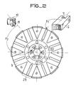
- FIG. 2 is a top view of the plate 3.
- the tool which will be described with the aid of FIG. 1 makes it possible, firstly, to obtain the external and internal movements simultaneously or not in order to form the bun at diameters B and C and, then to put the bun at the height H.
- This decomposition of the forming into at least two phases is essential to obtain a good quality of forming.
- the tool is built in two parts: the lower part is fixed on the press table; the upper part is coupled to the press nose.
- the lower part consists of a sole 2 which fixes it to the press table, not shown.
- On this sole 2 rest the central pyramidal cam 4 and several peripheral cams 5 as well as chan delles 14 which support a crown which one calls "Bottom of matrix” 13,
- the cam 4 and the candles 14 are fixed on the sole 2 by means of a wedging washer 15 aimed on this same sole 2.
- On the cam 4 which has a cylindrical body slides a plate 3. At rest it is retained on the bottom of the matrix 13 and maintained in this position under the action of springs 18 guided by rods 19.
- the plate 3 has several radial grooves.
- these radial grooves are each represented in two parts bounded by the circular groove 22 which receives the bottom of the die 13.
- This groove divides the plate 3 into two zones.
- the outer zone has grooves 23, each receiving an outer matrix element 6.
- the arrow F 1 indicates the positioning of the axis of symmetry of the matrix element 6.
- the inner zone has grooves 25 with a flat bottom, the arrow F 2 placing the axis of symmetry of one of the elements of inner matrix 10 which is inserted therein.
- a cover 17 and a crown cap 16 are fixed by screws to the plate 3 and thus complete the guiding of the matrix elements 6 and 10.
- the external matrix element 6 of parallelepipedal force has towards the center, the forming part in an arc in circle and at the rear, a yoke which receives a roller 7.
- a stop 9 integral with the matrix element 6 receives a permanent thrust under the action of the spring 8 which exerts a sufficient force to keep the contact between the roller 7 and cam 5.
- the inner matrix element 10 the forming part of which is in an arc, has a yoke at the rear which receives a roller 11.
- the permanent contact between the roller 11 and one of the facets of the cam 4 is ensured by a spring rubber crown 12.
- This spring is placed in a groove made in the interior matrix elements 10.
- the upper part is identical to the lower part, the sole 1 differing from the sole 2 only by the presence of the fastening elements on the press nose.
- the upper and lower parts may be different in size.
- the buns may also not have a circular shape and a constant height H. In this case, it suffices to adapt the profile of the matrix elements and of the matrix base to the buns.
- the operation of the tool is based on the decomposition of a vertical movement given by the press cylinder, into several radial movements received by the die elements.
- the motors of these resulting movements are rollers rolling on cams.
- the stator 20 is the connecting element between the lower and upper parts. It receives the movement from the upper part and transmits it to the lower part. By means of a prior balance between the two parties, we verify that they act simultaneously. The upper and lower parts travel their way at the same time.
- the forming operation takes place as follows. At rest, the upper part of the tool is raised enough to allow the stator to access the lower part. The stator rests on the cover 17 of the lower part. The upper part descends and comes to bear on the face A of the stator, by means of the cover 17a of the upper part. It is the first phase of forming. The rollers 7 and 11 roll on the slopes of the cams 5 and 4 and cause the displacement of the matrix elements 6 and 10 towards the bun 21.
- the end of the first phase corresponds to the instant when the rollers 7 and 11 pass from the sloping face of the cams 5 and 4 to the vertical face.
- the diameters B and C of the bun are formed and the faces in an arc of the matrix elements 6 and 10 are contiguous with those of the matrix bottom 13. The bun is trapped.
- the matrix elements 6 and 10 no longer move because their rollers roll on a vertical face and parallel to the direction of movement given by the press cylinder.
- the plate 3 comes to bear on the setting washer 15.
- the height H of the bun is obtained.
- the upper part rises, the mechanism resumes its rest position.
- the stator buns are formed.
- Recesses can be arranged by matrix elements of predetermined shape.
Abstract
Description
La présente invention se rapporte à la réalisation d'un outil de presse destiné au formage des têtes de bobine qui sont situées de part et d'autre d'un stator de moteur.The present invention relates to the production of a press tool intended for forming the coil heads which are located on either side of a motor stator.
Habituellement, cette opération est exécutée à partir d'une machine de formage dans laquelle les différents mouvements ont leurs propres origines et sont indépendants les uns par rapport aux autres.Usually, this operation is carried out from a forming machine in which the different movements have their own origins and are independent from each other.
Ces machines sont conçues avec une très grande variété de mécanismes (systèmes hydraulique, pneumatique etc.). Elles sont complexes et coûteuses, avec des temps de cycle assez lents.These machines are designed with a very wide variety of mechanisms (hydraulic, pneumatic systems, etc.). They are complex and expensive, with fairly slow cycle times.
Il existe également des outils ou montages de formage qui s'adaptent sur des presses "Col de Cygne" animées d'un seul mouvement vertical obtenu à partir d'un vérin hydraulique.There are also forming tools or assemblies which can be adapted to "Swan Neck" presses driven by a single vertical movement obtained from a hydraulic cylinder.
Ces montages sont généralement incomplets car il leur manque un ou plusieurs mouvements pour obtenir un formage satisfaisant. Avec ces montages, il est impossible de décaler les différentes phases de l'opération.These assemblies are generally incomplete because they lack one or more movements to obtain satisfactory forming. With these arrangements, it is impossible to offset the different phases of the operation.
Pour remédier à ces divers inconvénients, l'invention propose un outil de presse pour formage des têtes de bobine de part et d'autre d'un stator de moteur électrique, en cotes intérieure et extérieure et en hauteur, monté en deux parties formantes sur une table et un nez de presse, les deux parties formantes étant de structures identiques et comportant chacune un jeu de cames latérales et une came centrale de tel profil qu'au cours d'un même mouvement de descente de presse, le formage simultané des deux têtes de bobine inférieure et supérieure est assuré en deux phases.To remedy these various drawbacks, the invention provides a press tool for forming the coil heads on either side of an electric motor stator, in internal and external dimensions and in height, mounted in two forming parts on a press table and nose, the two forming parts being of identical structures and each comprising a set of lateral cams and a central cam of such a profile that during the same press down movement, the simultaneous forming of the two lower and upper coil heads is provided in two phases.
Le description et les figures annexées permettent d'expliquer une application de l'invention par laquelle celle-ci sera mieux comprise. L'application décrite concerne un formage de têtes de bobine cylindrique.The description and the appended figures make it possible to explain an application of the invention by which it will be better understood. The application described relates to the forming of cylindrical coil heads.
La figure 1 est une vue en coupe de l'outil, le stator étant en place, la presse commençant sa descente.Figure 1 is a sectional view of the tool, the stator being in place, the press starting its descent.
La figure 2 est une vue de dessus du plateau 3.FIG. 2 is a top view of the
Les têtes de bobine 21 appelées plus couramment "Chignons" sont disposées de part et d'autre du paquet de fer 20 du stator. L'opération de formage a pour but de conformer ces têtes de bobine suivant trois dimensions bien définies et se rapportant respectivement :
- - au diamètre extérieur B
- - au diamètre intérieur C
- - à la hauteur H.
- - outside diameter B
- - inside diameter C
- - at height H.
Pour obtenir les trois cotes B, C, et H, on a besoin de trois mouvements agissant sur des éléments de matrices. En particulier pour réaliser les cotes B et C, on agit sur plusieurs éléments de matrice extérieurs et intérieurs. Ces éléments sont formés de secteurs convergents.To obtain the three dimensions B, C, and H, we need three movements acting on elements of matrices. In particular to carry out the dimensions B and C, one acts on several elements of external and internal matrix. These elements are made up of converging sectors.
L'outil qui va être décrit à l'aide de la figure 1, permet d'obtenir, en premier lieu les mouvements extérieurs et intérieurs simultanément ou non afin de former le chignon aux diamètres B et C et, ensuite de mettre le chignon à la hauteur H. Cette décomposition du formage en au moins deux phases est indispensable pour obtenir une bonne qualité de formage.The tool which will be described with the aid of FIG. 1 makes it possible, firstly, to obtain the external and internal movements simultaneously or not in order to form the bun at diameters B and C and, then to put the bun at the height H. This decomposition of the forming into at least two phases is essential to obtain a good quality of forming.
L'outil est construit en deux parties : la partie inférieure est fixée sur la table de la presse ; la partie supérieure est accouplée au nez de la presse. La partie inférieure se compose d'une semelle 2 qui sa fixe sur la table de la presse non représentée. Sur cette semelle 2 reposent la came pyramidale centrale 4 et plusieurs cames périphériques 5 ainsi que des chandelles 14 qui supportent une couronne que l'on appelle "Fond de matrice" 13, La came 4 et les chandelles 14 sont fixées sur la semelle 2 par l'intermédiaire d'une rondelle de calage 15 visée sur cette même semelle 2. Sur la came 4 qui a un corps cylindrique coulisse un plateau 3. Au repos il est retenu sur le fond de matrice 13 et maintenu dans cette position sous l'action de ressorts 18 guidés par des tiges 19. Le plateau 3 possède plusieurs rainures radiales.The tool is built in two parts: the lower part is fixed on the press table; the upper part is coupled to the press nose. The lower part consists of a sole 2 which fixes it to the press table, not shown. On this sole 2 rest the central
A la figure 2, ces rainures radiales sont représentées en chacune deux parties limitées par la gorge circulaire 22 qui reçoit le fond de matrice 13. Cette gorge partage le plateau 3 en deux zones. La zone extérieure comporte des rainures 23, chacune recevant un élément de matrice extérieure 6. La flèche F1 indique le positionnement de l'axe de symétrie de l'élément de matrice 6. La zone intérieure comporte des rainures 25 à fond plat, la flèche F2 plaçant l'axe de symétrie de l'un des éléments de matrice intérieure 10 qui s'y insère.In FIG. 2, these radial grooves are each represented in two parts bounded by the
Un couvercle 17 et un chapeau 16 en couronne se fixent par vis sur le plateau 3 et complètent ainsi le guidage des éléments de matrice 6 et 10. L'élément de matrice extérieur 6 de force parallélépipédique possède vers le centre, la partie formante en arc de cercle et à l'arrière, une chape qui reçoit un galet 7. Une butée 9 solidaire de l'élément de matrice 6 reçoit une poussée permanente sous l'action du ressort 8 qui exerce une force suffisante pour garder le contact entre le galet 7 et la came 5.A
L'élément de matrice intérieur 10 dont la partie formante est en arc de cercle, possède à l'arrière une chape qui reçoit un galet 11. Le contact permanent entre le galet 11 et une des facettes de la came 4 est assuré par un ressort en caoutchouc en forme de couronne 12.The
Ce ressort est placé dans une gorge exécutée dans les éléments de matrice intérieures 10.This spring is placed in a groove made in the
Dans l'outil décrit ci-dessus, la partie supérieure est identique à la partie inférieure, la semelle 1 ne différant de la semelle 2 que par la présence des éléments de fixation sur le nez de presse.In the tool described above, the upper part is identical to the lower part, the sole 1 differing from the sole 2 only by the presence of the fastening elements on the press nose.
Pour des raisons de dissymétrie entre les chignons supérieur et inférieur du stator, les parties supérieure et inférieure peuvent être différentes en dimension.For reasons of asymmetry between the upper and lower buns of the stator, the upper and lower parts may be different in size.
Ces différences se situent au niveau des parties formantes des éléments de matrice 6 et 10 et du fond de matrice 13 et correspondent à des différences entre les cotes B, C et H des chighons. Les chignons peuvent également ne pas avoir une forme circulaire ainsi qu'une hauteur H constante. Dans ce cas, il suffit d'adapter le profil des éléments de matrice et du fond de matrice aux chignons.These differences are located at the level of the forming parts of the
Le fonctionnement de l'outil est basé sur la décomposition d'un mouvement vertical donné par le vérin de la presse, en plusieurs mouvements radiaux reçus par les éléments de matrice. Les moteurs de ces mouvements résultants sont des galets roulant sur des cames.The operation of the tool is based on the decomposition of a vertical movement given by the press cylinder, into several radial movements received by the die elements. The motors of these resulting movements are rollers rolling on cams.
Le stator 20 est l'élément de laison entre les parties inférieure et supérieure. Il reçoit le mouvement de la partie supérieure et le transmet à la partie inférieure. De par un équilibre préalable entre les deux parties, on vérifie qu'elles agissent simultanément. Les parties supérieure et inférieure parcourent leur chemin en même temps.The
Pour la misa on oeuvre de l'outil,-il a été volontairement choisi de décrire un mécanisme formant 2 chignons identiques. Les diamètres extérieur et intérieur du chignon B et C sont formés simultanément. Il est entendu que pour former successivement l'intérieur et l'extérieur du chignon, il suffit de modifier le profil des cames 4 et 5.For the misa on work of the tool, it was deliberately chosen to describe a mechanism forming 2 identical buns. The outside and inside diameters of the bun B and C are formed simultaneously. It is understood that to successively form the interior and the outside of the bun, just modify the profile of
L'opération de formage se déroule de la façon suivante. Au repos, la partie supérieure de l'outil est suffisamment remontée pour permettre l'accès du stator à la partie inférieure. Le stator repose sur le couvercle 17 de la partie inférieure. La partie supérieure descend et vient prendre appui sur la face A du stator, par l'intermédiaire du couvercle 17 bis de la partie supérieure. C'est la première phase du formage. Les galets 7 et 11 roulent sur les pentes des cames 5 et 4 et provoquent le déplacement des éléments de matrice 6 et 10 vers le chignon 21.The forming operation takes place as follows. At rest, the upper part of the tool is raised enough to allow the stator to access the lower part. The stator rests on the
La fin de la première phase correspond à l'instant où les galets 7 et 11 passent de la face en pente des cames 5 et 4 à la face verticale. Les diamètres B et C du Chignon sont formés et les faces en arc de cercle des éléments de matrice 6 et 10 sont contigues à celles du fond de matrice 13. Le chignon est prisonnier.The end of the first phase corresponds to the instant when the
Dans la 2ème phase, les éléments de matrice 6 et 10 ne se déplacent plus car leurs galets roulent sur une face verticale et parallèle à la direction du mouvement donné par le vérin de la presse.In the 2nd phase, the
Le plateau 3 vient en appui sur la rondelle de calage 15. La hauteur H du chignon est obtenue. La partie supérieure remonte, le mécanisme reprend se position repos. Les chignons du stator sont formés.The
D'autres formes peuvent être données aux têtes de bobine. Des évidements peuvent être aménagés par des éléments de matrice de forme prédéterminée.Other shapes can be given to the coil heads. Recesses can be arranged by matrix elements of predetermined shape.
Claims (6)
Applications Claiming Priority (2)
| Application Number | Priority Date | Filing Date | Title |
|---|---|---|---|
| FR7931490 | 1979-12-21 | ||
| FR7931490A FR2472295A1 (en) | 1979-12-21 | 1979-12-21 | PRESS TOOL FOR FORMING COIL HEADS PROVIDED ON EITHER A STATOR, AND COIL HEADS OBTAINED USING SUCH A TOOL |
Publications (2)
| Publication Number | Publication Date |
|---|---|
| EP0031739A1 true EP0031739A1 (en) | 1981-07-08 |
| EP0031739B1 EP0031739B1 (en) | 1983-10-19 |
Family
ID=9233099
Family Applications (1)
| Application Number | Title | Priority Date | Filing Date |
|---|---|---|---|
| EP19800401682 Expired EP0031739B1 (en) | 1979-12-21 | 1980-11-25 | Pressing tool for forming end windings situated at both sides of a stator, and end windings obtained with such a tool |
Country Status (3)
| Country | Link |
|---|---|
| EP (1) | EP0031739B1 (en) |
| DE (1) | DE3065396D1 (en) |
| FR (1) | FR2472295A1 (en) |
Cited By (5)
| Publication number | Priority date | Publication date | Assignee | Title |
|---|---|---|---|---|
| WO1992005619A1 (en) * | 1990-09-20 | 1992-04-02 | Advanced Machine And Tool Corporation | Apparatus for forming of stator coil end turns |
| WO1997034358A1 (en) * | 1996-03-12 | 1997-09-18 | Statomat Special Machines Limited | Press tools |
| WO1998038722A1 (en) * | 1997-02-28 | 1998-09-03 | Elmotec Elektro-Motoren-Technik Gmbh | Device for drawing in coils into grooves of stator laminated cores in electrical machines |
| EP1304789A1 (en) * | 2001-10-12 | 2003-04-23 | Pavesi S.R.L. | Apparatus and method for forming winding heads in dynamo-electric machine cores |
| CN103227538A (en) * | 2013-04-23 | 2013-07-31 | 大连德新机电技术工程有限公司 | Workpiece turnover device for reshaping and binding of front and rear ends of wound core |
Families Citing this family (1)
| Publication number | Priority date | Publication date | Assignee | Title |
|---|---|---|---|---|
| CN105344827A (en) * | 2015-11-30 | 2016-02-24 | 宁波东港紧固件制造有限公司 | Micromotor shell once molding mold |
Citations (3)
| Publication number | Priority date | Publication date | Assignee | Title |
|---|---|---|---|---|
| US3593405A (en) * | 1969-09-05 | 1971-07-20 | Gen Electric | Apparatus for forming winding end turns |
| FR2146431A1 (en) * | 1971-07-20 | 1973-03-02 | Appt E | |
| FR2258035A1 (en) * | 1974-01-14 | 1975-08-08 | Gen Electric |
-
1979
- 1979-12-21 FR FR7931490A patent/FR2472295A1/en active Granted
-
1980
- 1980-11-25 EP EP19800401682 patent/EP0031739B1/en not_active Expired
- 1980-11-25 DE DE8080401682T patent/DE3065396D1/en not_active Expired
Patent Citations (3)
| Publication number | Priority date | Publication date | Assignee | Title |
|---|---|---|---|---|
| US3593405A (en) * | 1969-09-05 | 1971-07-20 | Gen Electric | Apparatus for forming winding end turns |
| FR2146431A1 (en) * | 1971-07-20 | 1973-03-02 | Appt E | |
| FR2258035A1 (en) * | 1974-01-14 | 1975-08-08 | Gen Electric |
Cited By (7)
| Publication number | Priority date | Publication date | Assignee | Title |
|---|---|---|---|---|
| WO1992005619A1 (en) * | 1990-09-20 | 1992-04-02 | Advanced Machine And Tool Corporation | Apparatus for forming of stator coil end turns |
| WO1997034358A1 (en) * | 1996-03-12 | 1997-09-18 | Statomat Special Machines Limited | Press tools |
| US6155094A (en) * | 1996-03-12 | 2000-12-05 | Statomat Special Machines Ltd. | Pressing tool for forming winding end turns in a stator |
| WO1998038722A1 (en) * | 1997-02-28 | 1998-09-03 | Elmotec Elektro-Motoren-Technik Gmbh | Device for drawing in coils into grooves of stator laminated cores in electrical machines |
| EP1304789A1 (en) * | 2001-10-12 | 2003-04-23 | Pavesi S.R.L. | Apparatus and method for forming winding heads in dynamo-electric machine cores |
| CN103227538A (en) * | 2013-04-23 | 2013-07-31 | 大连德新机电技术工程有限公司 | Workpiece turnover device for reshaping and binding of front and rear ends of wound core |
| CN103227538B (en) * | 2013-04-23 | 2015-05-20 | 大连德新机电技术工程有限公司 | Workpiece turnover device for reshaping and binding of front and rear ends of wound core |
Also Published As
| Publication number | Publication date |
|---|---|
| FR2472295B1 (en) | 1983-01-21 |
| EP0031739B1 (en) | 1983-10-19 |
| DE3065396D1 (en) | 1983-11-24 |
| FR2472295A1 (en) | 1981-06-26 |
Similar Documents
| Publication | Publication Date | Title |
|---|---|---|
| US7412810B2 (en) | Packaging device for covering and sealing cover film onto tray | |
| FR2478497A1 (en) | PUNCHING PRESS WITH TOOL HOLDER TURRETS | |
| EP0323791A1 (en) | Punch tool for a drawing press device | |
| EP0031739A1 (en) | Pressing tool for forming end windings situated at both sides of a stator, and end windings obtained with such a tool | |
| US4570474A (en) | Apparatus for bending metal plate in widthwise direction | |
| JPH0114352Y2 (en) | ||
| FR2625454A1 (en) | TOOL FOR FILLING PRESS | |
| EP0491602B1 (en) | Device for press-forming sheet materials and especially metal blanks | |
| FR2481584A1 (en) | APPARATUS FOR FORMING AN INTERVAL WITHOUT COUPLING ELEMENTS ON TWO CONTINUOUS CLOSURE BANDS | |
| CN117358838A (en) | Stamping forming device of automobile luggage frame bottom plate | |
| US5741386A (en) | Apparatus and method for squeeze-gluing decorations | |
| JPH0327698Y2 (en) | ||
| FR2646623A1 (en) | Press tool for deep-drawing slightly shaped workpieces | |
| JPS6310738Y2 (en) | ||
| FR2852552A1 (en) | TOOLS FOR TRIMMING FORGED MECHANICAL PARTS | |
| EP0997208A1 (en) | Transfer arrangement of workpieces between two stations of a press tool | |
| CN113263342B (en) | Auxiliary device for processing bicycle chain wheel | |
| FR2615141A1 (en) | Engraving machine | |
| CN215393166U (en) | Rotary welding mechanism | |
| CN209969377U (en) | Foot fork punching and spreading die | |
| JPH0356194Y2 (en) | ||
| FR2644102A1 (en) | Device making it possible to produce a hydraulic press with at least one thrust axis which can be displaced over the entire work zone on demand | |
| RU2008113C1 (en) | Ring part straightening-calibrating die | |
| JP4398002B2 (en) | Punch press | |
| JPH0751725Y2 (en) | Magnetron Anode Curling Device |
Legal Events
| Date | Code | Title | Description |
|---|---|---|---|
| PUAI | Public reference made under article 153(3) epc to a published international application that has entered the european phase |
Free format text: ORIGINAL CODE: 0009012 |
|
| AK | Designated contracting states |
Designated state(s): DE GB IT |
|
| 17P | Request for examination filed |
Effective date: 19810805 |
|
| ITF | It: translation for a ep patent filed |
Owner name: JACOBACCI & PERANI S.P.A. |
|
| GRAA | (expected) grant |
Free format text: ORIGINAL CODE: 0009210 |
|
| AK | Designated contracting states |
Designated state(s): DE GB IT |
|
| REF | Corresponds to: |
Ref document number: 3065396 Country of ref document: DE Date of ref document: 19831124 |
|
| PLBE | No opposition filed within time limit |
Free format text: ORIGINAL CODE: 0009261 |
|
| STAA | Information on the status of an ep patent application or granted ep patent |
Free format text: STATUS: NO OPPOSITION FILED WITHIN TIME LIMIT |
|
| 26N | No opposition filed | ||
| ITTA | It: last paid annual fee | ||
| PGFP | Annual fee paid to national office [announced via postgrant information from national office to epo] |
Ref country code: GB Payment date: 19951020 Year of fee payment: 16 |
|
| PGFP | Annual fee paid to national office [announced via postgrant information from national office to epo] |
Ref country code: DE Payment date: 19951021 Year of fee payment: 16 |
|
| PG25 | Lapsed in a contracting state [announced via postgrant information from national office to epo] |
Ref country code: GB Effective date: 19961125 |
|
| GBPC | Gb: european patent ceased through non-payment of renewal fee |
Effective date: 19961125 |
|
| PG25 | Lapsed in a contracting state [announced via postgrant information from national office to epo] |
Ref country code: DE Effective date: 19970801 |