EP0031688A2 - Electric motor start up control - Google Patents
Electric motor start up control Download PDFInfo
- Publication number
- EP0031688A2 EP0031688A2 EP80304621A EP80304621A EP0031688A2 EP 0031688 A2 EP0031688 A2 EP 0031688A2 EP 80304621 A EP80304621 A EP 80304621A EP 80304621 A EP80304621 A EP 80304621A EP 0031688 A2 EP0031688 A2 EP 0031688A2
- Authority
- EP
- European Patent Office
- Prior art keywords
- motor
- current
- period
- load
- varying means
- Prior art date
- Legal status (The legal status is an assumption and is not a legal conclusion. Google has not performed a legal analysis and makes no representation as to the accuracy of the status listed.)
- Withdrawn
Links
- 238000004804 winding Methods 0.000 claims abstract description 31
- NJPPVKZQTLUDBO-UHFFFAOYSA-N novaluron Chemical compound C1=C(Cl)C(OC(F)(F)C(OC(F)(F)F)F)=CC=C1NC(=O)NC(=O)C1=C(F)C=CC=C1F NJPPVKZQTLUDBO-UHFFFAOYSA-N 0.000 claims description 10
- 239000003507 refrigerant Substances 0.000 abstract description 2
- 239000012530 fluid Substances 0.000 abstract 1
- 239000003990 capacitor Substances 0.000 description 10
- 238000004378 air conditioning Methods 0.000 description 2
- 230000005611 electricity Effects 0.000 description 2
- 238000010304 firing Methods 0.000 description 2
- 230000001960 triggered effect Effects 0.000 description 2
- 230000001419 dependent effect Effects 0.000 description 1
- 230000000994 depressogenic effect Effects 0.000 description 1
- 230000006698 induction Effects 0.000 description 1
- 238000009434 installation Methods 0.000 description 1
- 239000007858 starting material Substances 0.000 description 1
Images
Classifications
-
- H—ELECTRICITY
- H02—GENERATION; CONVERSION OR DISTRIBUTION OF ELECTRIC POWER
- H02P—CONTROL OR REGULATION OF ELECTRIC MOTORS, ELECTRIC GENERATORS OR DYNAMO-ELECTRIC CONVERTERS; CONTROLLING TRANSFORMERS, REACTORS OR CHOKE COILS
- H02P1/00—Arrangements for starting electric motors or dynamo-electric converters
- H02P1/16—Arrangements for starting electric motors or dynamo-electric converters for starting dynamo-electric motors or dynamo-electric converters
- H02P1/42—Arrangements for starting electric motors or dynamo-electric converters for starting dynamo-electric motors or dynamo-electric converters for starting an individual single-phase induction motor
- H02P1/44—Arrangements for starting electric motors or dynamo-electric converters for starting dynamo-electric motors or dynamo-electric converters for starting an individual single-phase induction motor by phase-splitting with a capacitor
-
- H—ELECTRICITY
- H02—GENERATION; CONVERSION OR DISTRIBUTION OF ELECTRIC POWER
- H02P—CONTROL OR REGULATION OF ELECTRIC MOTORS, ELECTRIC GENERATORS OR DYNAMO-ELECTRIC CONVERTERS; CONTROLLING TRANSFORMERS, REACTORS OR CHOKE COILS
- H02P23/00—Arrangements or methods for the control of AC motors characterised by a control method other than vector control
- H02P23/20—Controlling the acceleration or deceleration
Definitions
- the present invention relates to apparatus including an electric motor and start up control apparatus.
- the starting current for a motor driving a compressor may be as high as five times the running current, whereas it is often desirable to reduce the starting current to less than twice the running current.
- the starting current can be made less pronounced by use of a primary resistance starter, as described for example in "The Electrical Engineers Reference Book", section 9-14, llth edition, published in 1964 by George Newnes Ltd.
- the reduced current flowing through the motor reduces the motor torque, and the torque may be found to be insufficient to bring the motor up to its normal running speed.
- the present invention seeks to provide means automatically to reduce the current due to, and the load on, an electric motor during starting thereof.
- the invention has particular relevance to induction motors of the capacitor start and split phase types.
- apparatus comprising an electric motor, a device which is driven by the motor and which imposes a load on the motor, load reduction means to reduce the imposed load during a motor start up period, current varying means operative during the motor start up period to reduce the current supplied to the motor, and control means to sense the and of the motor start up period and in response thereto to cut out the load reduction means and to cause the current varying means to cease current reduction.
- a motor 10 driving a compressor (not shown) of an air conditioning plant or similar installation is connected to an AC supply through a starting circuit 13.
- Leads 11 and 12 of the AC supply are respectively connected to input terminals 14 and 19.
- Terminal 14 is connected through a main switch 15 to an output terminal 16, to which both the main winding 17 and the auxiliary winding 18 of the motor are connected.
- the other terminal 19 is connected through a motor protection device 21 and a start resistor 22 to output terminal 20, which is in turn connected to the main winding 17 of the motor 10.
- the auxiliary winding 18 is also connected to a further output terminal 23 of the starting circuit 13, this terminal 23 being connected to terminal 19 through the protection device 21 and a running capacitor 30.
- the main switch 15 is operated by a relay 24 through which current flows on depression of a motor start button 25.
- the chassis of the starting circuit may be earthed at 26.
- a first relay 31 is actuable in response to back EMF generated in the auxiliary winding 18 to close a normally open switch 27 when a predetermined critical value of the back EMF is obtained. Closure of switch 27 brings into operation a shorting loop 28 to short out starting resistor 22 and the motor protection device 21.
- a second relay 32 is actuable in response to back EMF generated in the main winding 17 to open normally closed switches 33 and 29 upon attainment of a predetermined critical back EMF. Opening of switch 33 cuts out a starting capacitor 34, and opening of switch 29 cuts out an off-loading device (generally indicated by L).
- the off-loading device L is in this embodiment a solenoid valve which is connected at one end permanently to terminal 19 and at the other end to terminal 14 through switch 29, such that the off-loading device L is actuated while there is insufficient back EMF in the main winding 17 to operate relay 32. Actuation of the off-loading device L removes from the motor 10 the full load of the compressor. Thus, the main load of the compressor operating normally is not applied to the motor 10 until the relay 32 is actuated, i.e. until the motor has attained sufficient speed to generate the predetermined back EMF.
- a one-way valve is placed in the high pressure line downstream of the solenoid valve to ensure that refrigerant cannot flood back from the condenser to the compressor pot and/or the evaporator when the off-loading solenoid valve opens to connect the discharge and suction pipes.
- the start button 25 is depressed to close the main switch 15.
- Switches 33 and 29 are in their normally closed positions, so that current flows to the off-loading device L, and the current supply to the auxiliary winding 18 flows through both capacitors 30 and 34 in parallel.
- relay 31 is triggered to short out the starting resistor 22 by closure of switch 27.
- relay 32 is also triggered to open switches 33 and 29, thereby to cut out start capacitor 34 and the off-loading device L so.that the full load of the compressor is taken up by the motor 10.
- Tests have been carried out which show that the starting current surge may be cut from 75A to below 25A, when using the circuit shown in Figure 1 of the drawing, and that the duration of the start made less than 0.5 sec. for normal operating voltages of 220 to 240 v. The tests also showed that the starting circuit was capable of operating efficiently for supply voltages below 190 v although the duration of the start increased as the supply voltage dropped.
- the whole of the reduced starting current flows through the protection device 21.
- This device is so chosen that, should the reduced starting current flow through it for more than an acceptable time (several times the normal start duration), the protection device 21 will open, thereby switching the motor off.
- the circuit is so arranged that the protection device 21 carries the auxiliary winding current continuously while power is applied to the motor.
- the characteristics of the protection device should also be such that if the current flowing through it exceeds the normal value of this current for a considerable period (several minutes) it will open and again switch off the motor 10. This protects the motor windings 17 and 18 against damage should either of the relays 31 or 32 fail or should the motor become heavily overloaded.
- motor 10 driving a compressor or the like is connected to an AC supply at terminals 14 and 19.
- Terminal 14 is connected through a sensing device 35 to detect total motor current to the main winding 17 and auxiliary winding 18 of the motor 10.
- Sensor 35 is typically a current transformer, although a small value resistor could be used.
- Terminal 19 is connected to the main winding 17 through a first phase controlled triac device 36; and to the auxiliary winding 18 through a running capacitor 30 in parallel with a start capacitor 34 and second triac device 37.
- a third triac device 38 is connected between terminal 19 and the off-loading device L, which is also connected directly to terminal 14.
- a second sensing device 39 is provided to generate an output responsive to rotation of the motor.
- This sensor 39 is shown as a device to monitor the back EMF across the auxiliary winding which increases sharply with motor speed, but it can alternatively be a tachometer type of device to produce an output proportional to rotational speed of the motor.
- the first triac device 36 controlling the main winding motor current is phase controlled by a ramp and pedestal control unit 41 which will be further described hereinafter. It would be possible to substitute for this triac device a saturable reactor but this would be more expensive, larger and heavier.
- Triac devices 37 and 38 act as simple switches in the same way as switches 33 and 29 of Figure 1, being operated to close at a predetermined level of operation of the motor 10. They could be replaced by electromechanical switches.
- Unit 40 contains means to generate a pedestal voltage which increases at a rate controlled by ramp rate setting 42 which may be any predetermined rate.
- the pedestal voltage may typically rise gradually under control of this setting over a period of 1 second.
- a ramp voltage is also generated and is preferably of the cosine modified type to give linear response.
- the pedestal voltage level is passed to ramp and pedestal phase control unit 41, which through output 43 gives a control signal to phase controlled triac device 36.
- the firing angle of triac device 36 thus gradually increases as the pedestal voltage rises, allowing a gradually increasing amount of current to flow through the main winding 17.
- the current in the auxiliary winding 18 will be at a maximum value limited only by the reactance of the two capacitors 34 and 30 in parallel.
- the voltage across the auxiliary winding 18 will therefore be minimal and hence the DC control voltage produced by the motor speed sensor 39 will be very small.
- the sensor 35 gives an AC signal dependent on the total motor current, which signal is amplified and rectified in unit 40 to give a DC output.
- a maximum value of current may be set in a hold current device 44, and is compared in unit 40 with the value indicated by the DC output originating from sensor 35 to produce an output to control the pedestal voltage, which is thereby increased by an amount sufficient to allow triac device 36 to fire earlier in each cycle so that the amount of current flowing to the main winding 17 brings the total current up to the maximum permissible value. After this, the current is held at this maximum permissible value and the motor 10 will accelerate, and as it does so the voltage across the auxiliary winding 18 will increase further.
- the firing angle of triac device 36 is reduced to allow less current to pass to the main winding 17. Also if the current increase is beyond the control afforded, i.e. a fault condition, the unit 40 switches all three triac devices off and produces a signal at an alarm output 45. Similarly, if the total current sensor 35 shows that the current has reached the maximum permissible value without any signal having been given by the motor speed sensor 39, a fault is also indicated.
- circuit shown in Figure 2 has advantages over the circuit of Figure 1 in that only sufficient current is drawn to start the motor under any set of conditions, and the inclusion of fail safe and alarm facilities are relatively straightforward with the electronic system of Figure 2.
Landscapes
- Engineering & Computer Science (AREA)
- Power Engineering (AREA)
- Motor And Converter Starters (AREA)
- Control Of Ac Motors In General (AREA)
- Control Of Positive-Displacement Pumps (AREA)
Abstract
Apparatus is disclosed comprising an electric motor (10), a device which is driven by the motor and which imposes the imposed load during a motor start up period, current varying means (22, 36) operative during the motor start up period to reduce the current supplied to the motor, and control means (31, 32, 39, 40) to sense the end of the motor start up period and in response thereto to cut out the load reduction means and to cause the current varying means to cease current reduction. The control means may be responsive to a back EMF generated by the motor and may be electronic or electro-mechanical. The current varying means may comprise a resistor in series with a main winding of the motor or may be a triac. The apparatus has particular application to electric motor driven compressors of refrigerant fluid.
Description
- The present invention relates to apparatus including an electric motor and start up control apparatus.
- When an electric motor is started up it has a heavy demand for current which falls off as the rotational speed of the motor increases. In fact the starting current for a motor driving a compressor may be as high as five times the running current, whereas it is often desirable to reduce the starting current to less than twice the running current. The starting current can be made less pronounced by use of a primary resistance starter, as described for example in "The Electrical Engineers Reference Book", section 9-14, llth edition, published in 1964 by George Newnes Ltd. The reduced current flowing through the motor, however, reduces the motor torque, and the torque may be found to be insufficient to bring the motor up to its normal running speed. The present invention seeks to provide means automatically to reduce the current due to, and the load on, an electric motor during starting thereof.
- The invention has particular relevance to induction motors of the capacitor start and split phase types.
- According to the present invention there is provided apparatus comprising an electric motor, a device which is driven by the motor and which imposes a load on the motor, load reduction means to reduce the imposed load during a motor start up period, current varying means operative during the motor start up period to reduce the current supplied to the motor, and control means to sense the and of the motor start up period and in response thereto to cut out the load reduction means and to cause the current varying means to cease current reduction.
- Embodiments of the invention will now be more particularly described by way of example and with reference to the accompanying drawings; in which
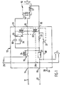
- Figure 1 shows a starting circuit and an electric motor according to a first embodiment of the invention; and
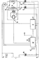
- Figure 2 shows a starting circuit and an electric motor according to a second embodiment of the invention.
- Referring now to Figure 1 of the drawings, a
motor 10 driving a compressor (not shown) of an air conditioning plant or similar installation is connected to an AC supply through astarting circuit 13.Leads 11 and 12 of the AC supply are respectively connected toinput terminals Terminal 14 is connected through amain switch 15 to anoutput terminal 16, to which both themain winding 17 and theauxiliary winding 18 of the motor are connected. Theother terminal 19 is connected through amotor protection device 21 and astart resistor 22 tooutput terminal 20, which is in turn connected to themain winding 17 of themotor 10. - The
auxiliary winding 18 is also connected to afurther output terminal 23 of thestarting circuit 13, thisterminal 23 being connected toterminal 19 through theprotection device 21 and a runningcapacitor 30. - The
main switch 15 is operated by arelay 24 through which current flows on depression of amotor start button 25. The chassis of the starting circuit may be earthed at 26. - A first relay 31 is actuable in response to back EMF generated in the
auxiliary winding 18 to close a normallyopen switch 27 when a predetermined critical value of the back EMF is obtained. Closure ofswitch 27 brings into operation a shortingloop 28 to short out startingresistor 22 and themotor protection device 21. - A
second relay 32 is actuable in response to back EMF generated in themain winding 17 to open normally closedswitches switch 33 cuts out astarting capacitor 34, and opening ofswitch 29 cuts out an off-loading device (generally indicated by L). - The off-loading device L is in this embodiment a solenoid valve which is connected at one end permanently to
terminal 19 and at the other end toterminal 14 throughswitch 29, such that the off-loading device L is actuated while there is insufficient back EMF in themain winding 17 to operaterelay 32. Actuation of the off-loading device L removes from themotor 10 the full load of the compressor. Thus, the main load of the compressor operating normally is not applied to themotor 10 until therelay 32 is actuated, i.e. until the motor has attained sufficient speed to generate the predetermined back EMF. In an air conditioning plan?, of which the motor and compressor form a part, a one-way valve is placed in the high pressure line downstream of the solenoid valve to ensure that refrigerant cannot flood back from the condenser to the compressor pot and/or the evaporator when the off-loading solenoid valve opens to connect the discharge and suction pipes. - In operation, the
start button 25 is depressed to close themain switch 15.Switches auxiliary winding 18 flows through bothcapacitors motor 10 increases due to the motor turning, relay 31 is triggered to short out thestarting resistor 22 by closure ofswitch 27. At the same time or subsequentlyrelay 32 is also triggered to openswitches start capacitor 34 and the off-loading device L so.that the full load of the compressor is taken up by themotor 10. - Tests have been carried out which show that the starting current surge may be cut from 75A to below 25A, when using the circuit shown in Figure 1 of the drawing, and that the duration of the start made less than 0.5 sec. for normal operating voltages of 220 to 240 v. The tests also showed that the starting circuit was capable of operating efficiently for supply voltages below 190 v although the duration of the start increased as the supply voltage dropped.
- It is believed that direct on-line starting of the compressor motor on a typical domestic supply could cause some voltage dips of 5 to 10%, a figure which would be unacceptable to most Electricity Supply Boards. By fitting the motor with the starting circuit as described with reference to Figure 1, the voltage dip is reduced by three times with respect to the no-load supply voltage. If however the voltage dip is compared to the supply voltage during operation of the compressor (load of approximately 15A) the dip is reduced to below 1%, a figure which would be acceptable to the Electricity Supply Boards.
- During start-up, before relay 31 operates, the whole of the reduced starting current flows through the
protection device 21. This device is so chosen that, should the reduced starting current flow through it for more than an acceptable time (several times the normal start duration), theprotection device 21 will open, thereby switching the motor off. - The circuit is so arranged that the
protection device 21 carries the auxiliary winding current continuously while power is applied to the motor. The characteristics of the protection device should also be such that if the current flowing through it exceeds the normal value of this current for a considerable period (several minutes) it will open and again switch off themotor 10. This protects themotor windings relays 31 or 32 fail or should the motor become heavily overloaded. - With the
starting resistor 22 ira series with the main winding 17 but not with theauxiliary winding 18, greater motor torque is generated during starting of themotor 10 than would be available if the resistor were to be inserted in the supply in such a position that it is in series with both windings. - Referring now to Figure 2 of the drawings, in which like parts are numbered as in Figure 1,
motor 10 driving a compressor or the like is connected to an AC supply atterminals Terminal 14 is connected through asensing device 35 to detect total motor current to the main winding 17 andauxiliary winding 18 of themotor 10.Sensor 35 is typically a current transformer, although a small value resistor could be used.Terminal 19 is connected to themain winding 17 through a first phase controlledtriac device 36; and to theauxiliary winding 18 through a runningcapacitor 30 in parallel with astart capacitor 34 andsecond triac device 37. Athird triac device 38 is connected betweenterminal 19 and the off-loading device L, which is also connected directly toterminal 14. - A
second sensing device 39 is provided to generate an output responsive to rotation of the motor. Thissensor 39 is shown as a device to monitor the back EMF across the auxiliary winding which increases sharply with motor speed, but it can alternatively be a tachometer type of device to produce an output proportional to rotational speed of the motor. Thefirst triac device 36 controlling the main winding motor current is phase controlled by a ramp andpedestal control unit 41 which will be further described hereinafter. It would be possible to substitute for this triac device a saturable reactor but this would be more expensive, larger and heavier. Triacdevices switches motor 10. They could be replaced by electromechanical switches. - In operation, power is applied to the circuit through
terminals third triac devices starting capacitor 34 and off-loadingdevice L. Unit 40 contains means to generate a pedestal voltage which increases at a rate controlled byramp rate setting 42 which may be any predetermined rate. The pedestal voltage may typically rise gradually under control of this setting over a period of 1 second. A ramp voltage is also generated and is preferably of the cosine modified type to give linear response. The pedestal voltage level is passed to ramp and pedestalphase control unit 41, which throughoutput 43 gives a control signal to phase controlledtriac device 36. The firing angle oftriac device 36 thus gradually increases as the pedestal voltage rises, allowing a gradually increasing amount of current to flow through themain winding 17. - Meanwhile the current in the
auxiliary winding 18 will be at a maximum value limited only by the reactance of the twocapacitors auxiliary winding 18 will therefore be minimal and hence the DC control voltage produced by themotor speed sensor 39 will be very small. As the current to themain winding 17 increases, a point will be reached where there is sufficient current to cause the motor to start turning, at which stage a back EMF will be produced in theauxiliary winding 18. At even quite slow rotational speeds of the motor this back EMF reaches a significant amplitude, and when it reaches a predetermined level, control of the pedestal voltage level is taken over by motorcurrent sensor 35. - The
sensor 35 gives an AC signal dependent on the total motor current, which signal is amplified and rectified inunit 40 to give a DC output. A maximum value of current may be set in a holdcurrent device 44, and is compared inunit 40 with the value indicated by the DC output originating fromsensor 35 to produce an output to control the pedestal voltage, which is thereby increased by an amount sufficient to allowtriac device 36 to fire earlier in each cycle so that the amount of current flowing to themain winding 17 brings the total current up to the maximum permissible value. After this, the current is held at this maximum permissible value and themotor 10 will accelerate, and as it does so the voltage across the auxiliary winding 18 will increase further. When this voltage reaches another predetermined amplitude representative of normally runningmotor speed unit 40 switches offtriac devices capacitor 34 and off-loading device L. At the sametime triac device 36 is switched fully open allowing the motor to run normally. - If, during starting, the current tries to exceed the permissible level, the firing angle of
triac device 36 is reduced to allow less current to pass to the main winding 17. Also if the current increase is beyond the control afforded, i.e. a fault condition, theunit 40 switches all three triac devices off and produces a signal at analarm output 45. Similarly, if the totalcurrent sensor 35 shows that the current has reached the maximum permissible value without any signal having been given by themotor speed sensor 39, a fault is also indicated. - The circuit shown in Figure 2 has advantages over the circuit of Figure 1 in that only sufficient current is drawn to start the motor under any set of conditions, and the inclusion of fail safe and alarm facilities are relatively straightforward with the electronic system of Figure 2.
- It will, of course, be appreciated that either of the circuits shown in Figures 1 and 2 can be made to operate without an off-loading device, although this would require a significantly larger and more powerful motor to be used.
Claims (10)
1. Apparatus comprising an electric motor (10) and a device whizh is driven by the motor and which imposes a load on the motor, characterised by load reduction means (L) to reduce the imposed load during a motor start up period, current varying means (22,36) operative during the motor start up period to reduce the current supplied to the motor, and control means (31,32,39,40) to sense the end of the motor start up period and in response thereto to cut out the load reduction means and to cause the current varying means to cease current reduction.
2. Apparatus as claimed in claim 1, wherein said control means is responsive to the rotational speed of the motor.
3. Apparatus as claimed in claim 2, wherein said control means is responsive to a back EMF generated by the motor.
4. Apparatus as claimed in any one of the preceding claims, wherein the load is a compressor and the load reduction means comprises a solenoid valve actuable by switch means.
5. Apparatus as claimed in any one of the preceding claims, wherein said current varying means comprises a resistor (22) in series with a main winding (17) of the motor.
6. Apparatus as claimed in claim 5, wherein said current varying means further comprises a switch (27) in parallel with said resistor and actuable to short out said resistor at the end of the start up period.
7. Apparatus as claimed in any one of claims 1 to 4, wherein said current varying means comprises a triac device (36) in series with a main winding (17) of the motor.
8. Apparatus as claimed in claim 7, wherein said triac device is controlled by a variable ramp and pedestal control voltage.
9. Apparatus as claimed in claim 8, further comprising means (35) to sense the total motor current, and in response thereto to vary the amplitude of the pedestal voltage to maintain the total motor current at a value which does not exceed a predetermined maximum value.
10. Apparatus as claimed in any one of claims 7 to 9, wherein said triac device is arranged to become fully conducting at the end of the start up period.
Applications Claiming Priority (2)
| Application Number | Priority Date | Filing Date | Title |
|---|---|---|---|
| GB7944431 | 1979-12-28 | ||
| GB7944431 | 1979-12-28 |
Publications (2)
| Publication Number | Publication Date |
|---|---|
| EP0031688A2 true EP0031688A2 (en) | 1981-07-08 |
| EP0031688A3 EP0031688A3 (en) | 1981-10-21 |
Family
ID=10510064
Family Applications (1)
| Application Number | Title | Priority Date | Filing Date |
|---|---|---|---|
| EP80304621A Withdrawn EP0031688A3 (en) | 1979-12-28 | 1980-12-19 | Electric motor start up control |
Country Status (8)
| Country | Link |
|---|---|
| EP (1) | EP0031688A3 (en) |
| AU (1) | AU6565680A (en) |
| DK (1) | DK548680A (en) |
| ES (1) | ES498171A0 (en) |
| GB (1) | GB2067370B (en) |
| GR (1) | GR72409B (en) |
| PT (1) | PT72289B (en) |
| ZA (1) | ZA807987B (en) |
Cited By (17)
| Publication number | Priority date | Publication date | Assignee | Title |
|---|---|---|---|---|
| GB2135539A (en) * | 1983-02-21 | 1984-08-30 | Associated Electical Ind Limit | Single phase induction motors |
| EP0319404A1 (en) * | 1987-12-02 | 1989-06-07 | STMicroelectronics S.A. | Electronic start circuit for an asynchronous motor |
| GB2212348A (en) * | 1987-11-10 | 1989-07-19 | Hawker Controls Ltd | Improvements in circuits for starting electric motors |
| WO1992022126A1 (en) * | 1991-06-07 | 1992-12-10 | Ascom Autelca Ltd. | Load-control circuit for a mains-powered asynchronous single-phase capacitor motor |
| EP0605788A3 (en) * | 1993-01-06 | 1994-12-21 | Mechanical Ingenuity Corp | Single phase AC motor speed control system. |
| EP1100190A2 (en) | 1999-11-12 | 2001-05-16 | Lg Electronics Inc. | Device and method for controlling the current supply and the static capacitance of a compressor |
| WO2001035520A1 (en) | 1999-11-12 | 2001-05-17 | Lg Electronics Inc. | Device and method for controlling supply of current and static capacitance to compressor |
| WO2002060046A1 (en) * | 2001-01-26 | 2002-08-01 | Auckland Uniservices Limited | Safety start |
| WO2003103128A1 (en) * | 2002-05-29 | 2003-12-11 | Bristol Compressors, Inc. | System and method for soft starting a three phase motor |
| EP1494346A2 (en) | 2003-07-04 | 2005-01-05 | B.D.G. El. S.P.A. | A controller device, in particular for induction motors and more particularly for compressors in refrigerating apparatuses. |
| GB2407441A (en) * | 2003-10-23 | 2005-04-27 | Matsushita Electric Industrial Co Ltd | Soft start with low voltage supplies |
| FR2872968A1 (en) * | 2004-07-08 | 2006-01-13 | Electricite De France | Domestic electric appliance module, has microprocessor which controls module that supplies electric motor in a progressive manner, after disconnection of additional capacitor from switch |
| AU2003235058B2 (en) * | 1999-11-12 | 2006-07-06 | Lg Electronics Inc. | Device and method for controlling supply of current and static capacitance to compressor |
| CN102072141A (en) * | 2011-02-23 | 2011-05-25 | 无锡和晶科技股份有限公司 | Control circuit capable of out-of-control prevention for compressor of refrigerator |
| EP2101405A3 (en) * | 2008-02-29 | 2013-04-24 | Johnson Controls Technology Company | Controlling switching of thyristors to reduce power loss in variable speed motor |
| EP3910785A1 (en) * | 2020-05-11 | 2021-11-17 | Rockwell Collins, Inc. | Failure detection in small ac motors |
| CN115697797A (en) * | 2020-06-03 | 2023-02-03 | 日立安斯泰莫株式会社 | Electric parking brake control device and electric parking brake control method |
Families Citing this family (3)
| Publication number | Priority date | Publication date | Assignee | Title |
|---|---|---|---|---|
| DE3311771A1 (en) * | 1983-03-31 | 1984-10-04 | Vorwerk & Co Interholding Gmbh, 5600 Wuppertal | MONITORING CIRCUIT FOR ELECTRIC MOTORS |
| US5164651A (en) * | 1991-06-27 | 1992-11-17 | Industrial Technology Research Institute | Starting-current limiting device for single-phase induction motors used in household electrical equipment |
| JP3126895B2 (en) * | 1994-08-31 | 2001-01-22 | 三菱電機株式会社 | Single-phase induction motor and refrigerator using the single-phase induction motor |
Family Cites Families (6)
| Publication number | Priority date | Publication date | Assignee | Title |
|---|---|---|---|---|
| DD87858A (en) * | ||||
| DE614232C (en) * | 1930-03-26 | 1935-06-04 | Siemens Schuckertwerke Akt Ges | Automatic device for controlling the idle valve with unloaded starting three-phase squirrel cage motors to drive compressors |
| DE1763405A1 (en) * | 1965-02-17 | 1971-11-11 | Bosch Gmbh Robert | Starting device for an electric universal motor |
| FR95086E (en) * | 1966-07-13 | 1970-06-19 | Unelec | Device for starting single-phase asynchronous motors. |
| DE1810885A1 (en) * | 1968-11-26 | 1970-06-11 | Kienzle Apparate Gmbh | Start-up circuit for brushless single-phase AC motors |
| US3671830A (en) * | 1970-06-24 | 1972-06-20 | Westinghouse Electric Corp | Single phase motor starting control apparatus |
-
1980
- 1980-12-16 GB GB8040253A patent/GB2067370B/en not_active Expired
- 1980-12-19 EP EP80304621A patent/EP0031688A3/en not_active Withdrawn
- 1980-12-22 ZA ZA00807987A patent/ZA807987B/en unknown
- 1980-12-22 DK DK548680A patent/DK548680A/en not_active Application Discontinuation
- 1980-12-22 AU AU65656/80A patent/AU6565680A/en not_active Abandoned
- 1980-12-23 GR GR63754A patent/GR72409B/el unknown
- 1980-12-26 PT PT72289A patent/PT72289B/en unknown
- 1980-12-26 ES ES498171A patent/ES498171A0/en active Granted
Cited By (31)
| Publication number | Priority date | Publication date | Assignee | Title |
|---|---|---|---|---|
| GB2135539A (en) * | 1983-02-21 | 1984-08-30 | Associated Electical Ind Limit | Single phase induction motors |
| GB2212348A (en) * | 1987-11-10 | 1989-07-19 | Hawker Controls Ltd | Improvements in circuits for starting electric motors |
| GB2212348B (en) * | 1987-11-10 | 1992-04-08 | Hawker Controls Ltd | Improvements in circuits for starting electric motors |
| EP0319404A1 (en) * | 1987-12-02 | 1989-06-07 | STMicroelectronics S.A. | Electronic start circuit for an asynchronous motor |
| FR2624321A1 (en) * | 1987-12-02 | 1989-06-09 | Sgs Thomson Microelectronics | ELECTRONIC CONTROL CIRCUIT FOR STARTING AN ASYNCHRONOUS MOTOR |
| WO1992022126A1 (en) * | 1991-06-07 | 1992-12-10 | Ascom Autelca Ltd. | Load-control circuit for a mains-powered asynchronous single-phase capacitor motor |
| EP0605788A3 (en) * | 1993-01-06 | 1994-12-21 | Mechanical Ingenuity Corp | Single phase AC motor speed control system. |
| US6747428B1 (en) | 1999-11-12 | 2004-06-08 | Lg Electronics Inc. | Device and method for controlling supply of current and static capacitance to compressor |
| AU778356B2 (en) * | 1999-11-12 | 2004-12-02 | Lg Electronics Inc. | Device and method for controlling supply of current and static capacitance to compressor |
| WO2001035521A1 (en) | 1999-11-12 | 2001-05-17 | Lg Electronics Inc. | Device and method for controlling supply of current and static capacitance to compressor |
| EP1232558B1 (en) * | 1999-11-12 | 2018-08-01 | LG Electronics, Inc. | Device and method for controlling supply of current and static capacitance to compressor |
| EP1100190A3 (en) * | 1999-11-12 | 2002-09-25 | Lg Electronics Inc. | Device and method for controlling the current supply and the static capacitance of a compressor |
| WO2001035520A1 (en) | 1999-11-12 | 2001-05-17 | Lg Electronics Inc. | Device and method for controlling supply of current and static capacitance to compressor |
| AU772836B2 (en) * | 1999-11-12 | 2004-05-06 | Lg Electronics Inc. | Device and method for controlling supply of current and static capacitance to compressor |
| EP1100190A2 (en) | 1999-11-12 | 2001-05-16 | Lg Electronics Inc. | Device and method for controlling the current supply and the static capacitance of a compressor |
| AU2003235058B2 (en) * | 1999-11-12 | 2006-07-06 | Lg Electronics Inc. | Device and method for controlling supply of current and static capacitance to compressor |
| AU2002228511B2 (en) * | 2001-01-26 | 2006-11-09 | Auckland Uniservices Limited | Safety start |
| WO2002060046A1 (en) * | 2001-01-26 | 2002-08-01 | Auckland Uniservices Limited | Safety start |
| US6903532B2 (en) | 2001-01-26 | 2005-06-07 | Auckland Uniservices Limited | Method and apparatus for starting an induction motor |
| US6781342B2 (en) | 2002-05-29 | 2004-08-24 | Bristol Compressors, Inc. | System and method for soft starting a three phase motor |
| WO2003103128A1 (en) * | 2002-05-29 | 2003-12-11 | Bristol Compressors, Inc. | System and method for soft starting a three phase motor |
| EP1494346A2 (en) | 2003-07-04 | 2005-01-05 | B.D.G. El. S.P.A. | A controller device, in particular for induction motors and more particularly for compressors in refrigerating apparatuses. |
| EP1494346A3 (en) * | 2003-07-04 | 2010-10-06 | B.D.G. El. S.P.A. | A controller device, in particular for induction motors and more particularly for compressors in refrigerating apparatuses. |
| GB2407441A (en) * | 2003-10-23 | 2005-04-27 | Matsushita Electric Industrial Co Ltd | Soft start with low voltage supplies |
| GB2407441B (en) * | 2003-10-23 | 2006-05-03 | Matsushita Electric Industrial Co Ltd | Soft start with low voltage supplies |
| FR2872968A1 (en) * | 2004-07-08 | 2006-01-13 | Electricite De France | Domestic electric appliance module, has microprocessor which controls module that supplies electric motor in a progressive manner, after disconnection of additional capacitor from switch |
| EP2101405A3 (en) * | 2008-02-29 | 2013-04-24 | Johnson Controls Technology Company | Controlling switching of thyristors to reduce power loss in variable speed motor |
| CN102072141A (en) * | 2011-02-23 | 2011-05-25 | 无锡和晶科技股份有限公司 | Control circuit capable of out-of-control prevention for compressor of refrigerator |
| EP3910785A1 (en) * | 2020-05-11 | 2021-11-17 | Rockwell Collins, Inc. | Failure detection in small ac motors |
| US11280836B2 (en) | 2020-05-11 | 2022-03-22 | Rockwell Collins, Inc. | Failure detection in small AC motors |
| CN115697797A (en) * | 2020-06-03 | 2023-02-03 | 日立安斯泰莫株式会社 | Electric parking brake control device and electric parking brake control method |
Also Published As
| Publication number | Publication date |
|---|---|
| ES8203177A1 (en) | 1982-02-16 |
| ZA807987B (en) | 1982-01-27 |
| PT72289A (en) | 1981-01-01 |
| DK548680A (en) | 1981-06-29 |
| AU6565680A (en) | 1981-07-02 |
| GB2067370A (en) | 1981-07-22 |
| GB2067370B (en) | 1984-01-25 |
| EP0031688A3 (en) | 1981-10-21 |
| ES498171A0 (en) | 1982-02-16 |
| PT72289B (en) | 1982-01-05 |
| GR72409B (en) | 1983-11-02 |
Similar Documents
| Publication | Publication Date | Title |
|---|---|---|
| EP0031688A2 (en) | Electric motor start up control | |
| US6320348B1 (en) | Time rate of change motor start circuit | |
| US4647825A (en) | Up-to-speed enable for jam under load and phase loss | |
| US7196491B2 (en) | System and method for stall detection of a motor | |
| CA2088626C (en) | Load-control circuit for a mains-powered asynchronous single-phase capacitor motor | |
| US5528120A (en) | Adjustable electronic potential relay | |
| US4307327A (en) | Control arrangement for single phase AC systems | |
| US4100469A (en) | Hybrid motor starter | |
| US4467257A (en) | Multiple speed induction motor | |
| HK1000503B (en) | Single-phase induction motor and refrigerator using the single-phase induction motor | |
| HK1000503A1 (en) | Single-phase induction motor and refrigerator using the single-phase induction motor | |
| US4734601A (en) | Noise suppression circuit for parallel resonant motor | |
| US5657194A (en) | Circuit and method for automatically resetting a solid state relay | |
| US3417290A (en) | Oil well pumping unit control circuit | |
| US3191114A (en) | Time delay motor starting system | |
| US4682263A (en) | Electrical short-cicruit monitoring arrangement for variable-speed, three-phase motors, including their feed lines | |
| US2976807A (en) | Electric motor-driven pump installation | |
| WO2005010630A1 (en) | Soft starter for asynchronous motor | |
| US4492911A (en) | Static phase converter | |
| US4422029A (en) | Instant reverse control circuit for a single phase motor | |
| SE515541C2 (en) | Device at a rectifier bridge | |
| US4533835A (en) | Control apparatus for hydraulically driven generator | |
| JPH035673A (en) | Freezing cycle device | |
| US4160196A (en) | Two-phase ac electric motor control circuit | |
| EP0087173B1 (en) | Self-starting single-phase synchronous motor |
Legal Events
| Date | Code | Title | Description |
|---|---|---|---|
| PUAI | Public reference made under article 153(3) epc to a published international application that has entered the european phase |
Free format text: ORIGINAL CODE: 0009012 |
|
| AK | Designated contracting states |
Designated state(s): AT BE CH DE FR IT LU NL SE |
|
| PUAL | Search report despatched |
Free format text: ORIGINAL CODE: 0009013 |
|
| AK | Designated contracting states |
Designated state(s): AT BE CH DE FR IT LU NL SE |
|
| 17P | Request for examination filed |
Effective date: 19820422 |
|
| STAA | Information on the status of an ep patent application or granted ep patent |
Free format text: STATUS: THE APPLICATION IS DEEMED TO BE WITHDRAWN |
|
| 18D | Application deemed to be withdrawn |
Effective date: 19840703 |
|
| RIN1 | Information on inventor provided before grant (corrected) |
Inventor name: BROWN, DAVID MICHAEL Inventor name: CHABRA, JANAK RAJ |