EP0031069B2 - A baseless incandescent lamp assembly - Google Patents
A baseless incandescent lamp assembly Download PDFInfo
- Publication number
- EP0031069B2 EP0031069B2 EP80107732A EP80107732A EP0031069B2 EP 0031069 B2 EP0031069 B2 EP 0031069B2 EP 80107732 A EP80107732 A EP 80107732A EP 80107732 A EP80107732 A EP 80107732A EP 0031069 B2 EP0031069 B2 EP 0031069B2
- Authority
- EP
- European Patent Office
- Prior art keywords
- incandescent lamp
- holding
- baseless incandescent
- socket body
- contact strip
- Prior art date
- Legal status (The legal status is an assumption and is not a legal conclusion. Google has not performed a legal analysis and makes no representation as to the accuracy of the status listed.)
- Expired
Links
Images

Classifications
-
- H—ELECTRICITY
- H01—ELECTRIC ELEMENTS
- H01R—ELECTRICALLY-CONDUCTIVE CONNECTIONS; STRUCTURAL ASSOCIATIONS OF A PLURALITY OF MUTUALLY-INSULATED ELECTRICAL CONNECTING ELEMENTS; COUPLING DEVICES; CURRENT COLLECTORS
- H01R33/00—Coupling devices specially adapted for supporting apparatus and having one part acting as a holder providing support and electrical connection via a counterpart which is structurally associated with the apparatus, e.g. lamp holders; Separate parts thereof
- H01R33/05—Two-pole devices
- H01R33/06—Two-pole devices with two current-carrying pins, blades or analogous contacts, having their axes parallel to each other
- H01R33/09—Two-pole devices with two current-carrying pins, blades or analogous contacts, having their axes parallel to each other for baseless lamp bulb
-
- H—ELECTRICITY
- H01—ELECTRIC ELEMENTS
- H01J—ELECTRIC DISCHARGE TUBES OR DISCHARGE LAMPS
- H01J5/00—Details relating to vessels or to leading-in conductors common to two or more basic types of discharge tubes or lamps
- H01J5/50—Means forming part of the tube or lamps for the purpose of providing electrical connection to it
-
- H—ELECTRICITY
- H01—ELECTRIC ELEMENTS
- H01K—ELECTRIC INCANDESCENT LAMPS
- H01K1/00—Details
- H01K1/42—Means forming part of the lamp for the purpose of providing electrical connection, or support for, the lamp
- H01K1/44—Means forming part of the lamp for the purpose of providing electrical connection, or support for, the lamp directly applied to, or forming part of, the vessel
Definitions
- the invention relates to a baseless incandescent lamp assembly
- a baseless incandescent lamp assembly comprising a baseless incandescent lamp including a flattened seal section and a pair of external lead wires led outward from the flattened seal section, a main socket body including inner surfaces for defining a lamp holding chamber to contain the flattened seal section of the baseless incandescent lamp, and a pair of conductive holding members for holding the flattened seal section of the baseless incandescent lamp in the main socket body, wherein the external lead wires are held and electrically connected to the conductive holding members by being pressed towards said conductive holding members, and each of the holding members includes a facing pair of pinch strips and a contact strip stretched therebetween, the said holding members being secured to the side portions of the seal section by clamping said side portions between the pinch strips.
- Document FR-A-2206 033 discloses such an incandescent lamp assembly.
- elastic contact members arranged in the main socket body enable electrical connections between the lamp and circuits which are supported by a board mechanically connected to a flange of the lamp assembly.
- Baseless incandescent lamps are generally used as illuminating light sources for dashboards of vehicles, and are available in combination with sockets with exclusive use. Such a socket is so designed as to be able to be mounted on a printing substrate on the backside of the dashboard.
- the external lead wires of the inserted baseless incandescent lamp extending along the outside surface of the flattened seal section, are held between and pressed by the flattened seal section and the holding member to be in electrical contact with the holding member.
- the external lead wires are liable to slip off the outside surface of the flattened seal section, and often fail to be securely held between the holding member and the flattened seal section, thereby causing defective electrical contact.
- the baseless incandescent lamp of this type in use, is mounted on the backside of a dashboard, as mentioned above, so that it requires a great deal of-labor to replace a defective baseless incandescent lamp assembly with a new one.
- the object of this invention is to provide a baseless incandescent lamp which is not liable to defective electrical contact and is adapted for mass production, requiring only easy manufacturing operations.
- the incandescent lamp assembly as described above according to the present invention is characterized in that said external lead wires are held and electrically connected to the conductive holding members by being pressed between the conductive holding members and the inside wall of the holding chamber, and that said contact strip includes a notch in the lower edge through which the external lead wire is extended between the contact strip and the inside wall of the holding chamber so that each of the external lead wires is pressed between the contact strip and the inside wall of the holding chamber.
- numeral 1 designates the main body of a lamp socket.
- the main lamp socket body 1 which is formed by integrally molding thermoplastic synthetic resin, includes a circular flange section 2 and a knob section 3 on the back side of the flange section 2.
- a lamp holding chamber 4 opening in the front of the flange section 2.
- the lamp holding chamber 4 is substantially in the form of a rectangle defined by wide front and rear sides and narrow lateral sides.
- a pair of fitting edge sections 5 protrude from the front of the flange section 2, located around the opening of the lamp holding chamber 4.
- fitting edge sections 5 each have an inside face with such radius of curvature that they may engage the front and rear sides of the bulb of a baseless incandescent lamp held in the socket body, thereby preventing the bulb from wobbling.
- Severally from the outside faces of the fitting edge sections 5 protrude stopping projections 6 spaced at a given distance from the front face of the flange section 2.
- Numeral 7 designates a baseless incandescent lamp which has a flattened seal section 9 formed by flattening the bottom portion of a cylindrical bulb and a filament 8 contained in the bulb.
- the flattened seal section 9 of the baseless incandescent lamp 7 is divided into left and right portions 9b and 9c by an exhaust tube 9a.
- Holding members 10 are attached severally to the left and right portions 9b and 9c. These holding members 10 are formed by pressing a brass plate, each having a facing pair of pinch strips 11 and a contact strip 12 which is bent substantially at right angles to the pinch strips and stretched therebetween to couple the same.
- the pinch strips 11 Vietnamese at their middle portions their respective pinch sections inwardly bent so as to approach each other.
- the baseless incandescent lamp 7 inserted between these pinch strips 11 has the left and right portions 9b and 9c of its flattened seal section 9 held severally between the pinch sections of the two pinch strips 11 by the spring action thereof.
- engaging grooves 13 are formed respectively at the basal parts of the front and rear sides of the flattened seal section 9 so that the pinch sections of the pinch strips 11 may be fitted in the grooves 13.
- the holding members 10 have a common open bottom side, and a lead wire notch 14 extends upward from the bottom end of each contact strip 12.
- a pair of external lead wires 15 of the baseless incandescent lamp 7 have their one ends electrically connected with the filament 8 and the other ends passing through the left and right seal portions 9b and 9c and extended from the bottom ends thereof to the outside.
- the outwardly extended external lead wire 15 are doubled and bent respectively toward both flanks of the baseless incandescent lamp 7.
- the tip end of each doubled lead wire 15 is bent upward at a point where it outwardly passes through the notch 14 of its corresponding contact strip 12, and extends along the outside face of the contact strip 12.
- the contact strip 12 may be in contact with or kept apart from the bent tip end portion of the doubled lead wire 15.
- the flattened seal section 9 of the baseless incandescent lamp 7 and the pair of holding members 10 pinching the flattened sealing section 9 therebetween are inserted in the lamp holding chamber 4 of the main socket body 1.
- the dimensions of the lamp holding chamber 4 are such that no substantial gap may be left between the outer peripheral surfaces of the paired holding members 10 holding the flattened seal section 9 and the inner peripheral surface of the holding chamber 4. Namely, the width of the holding chamber 4 is a little greater than the distance between the respective contact strips 12 of the two holding members 10, and the depth of the chamber 4 is a little greater than the distance between the pinch strips 11 of each holding member 10.
- each external lead wire 15 extending along the outside face of the contact strip 12 of its corresponding holding member 10 inserted in the lamp holding chamber 4 is held between the outside face of the contact strip 12 and the inside wall of the holding chamber 4, so that the electrical contact between the end portion of the lead wire 15 and the holding member 10 is secured.
- the top portions of the contact strips 12 are bent so as to be severally fitted in a pair of grooves 16 which are formed in the front of the flange section 2 of the main socket body 1, extending in the radial direction of the flange section 2.
- the top end portions of the contact strips 12 are projected a little ahead of the front of the flange section 2 so that they may elastically abut against power supply terminals of the printed substrate to be supplied with power when the main socket body 1 is mounted on the printed substrate.
- Respectively formed on both sides of the basal parts of the grooves 16 are caulked portions 17 which project on both side edges of the contact strips 12 to prevent the holding members 10 from slipping off the socket body.
- the caulked portion 17 may be easily made by the following manner.
- an ultrasonic oscillator having four projections 18 corresponding to both sides of the basal parts of the pair of grooves 16 of the flange section 2, the tip ends of these projections 18 being upwardly inclined toward the center lines of the grooves 16 as shown in Fig. 7.
- the inclined end portions of the projections 18 are pressed against both sides of the grooves 16 to heat and soften the same.
- softened resin is pushed toward the grooves 16 to be projected onto the top of the contact strips 12, thereby forming the caulked portions 17, as shown in Fig. 8.
- the projected caulked portions 17 enable the holding members 10 to be fixedly held in the main socket body 1 and prevented from slipping off the socket body.
- the portions 17 are formed by deforming the main socket body 1 by means of heat treatment, thereby preventing the holding members 10 from slipping out of the socket body 1.
- the holding member 10 may be secured to the socket body 1 by another means, which will be described with reference to Fig. 9 wherein like and same parts are denoted by the same numerals as used in Fig. 1.
- a holding member 10 has a contact strip 12 which has two protrusions 19 integral with the strip 12 and extending in the opposite directions from the sides of the strip 12.
- the distance between the free ends of the protrusions 19 is slightly longer than a lamp holding chamber 4 is broad.
- the lower side of each protrusion 19 is tapered so that the protrusion 19 is gradually slender toward its free end.
- the holding member 10 and the main socket body 1 may be connected to each other by means of an adhesive.
- the external lead wires are securely held between the holding members and the inner peripheral walls of the lamp holding chamber, so that there is no possibility of defective contact.
- the electrical connection between the external lead wires and the holding members is not limited to the case of the above-mentioned embodiment in which is obtained the hold of the lead wires between the contact strips of the holding members and the inner peripheral walls of the main socket body, and such connection may also be obtained holding the lead wires between the pinch strips and the inner peripheral walls, for example.
Landscapes
- Connecting Device With Holders (AREA)
- Fastening Of Light Sources Or Lamp Holders (AREA)
Description
- The invention relates to a baseless incandescent lamp assembly comprising a baseless incandescent lamp including a flattened seal section and a pair of external lead wires led outward from the flattened seal section, a main socket body including inner surfaces for defining a lamp holding chamber to contain the flattened seal section of the baseless incandescent lamp, and a pair of conductive holding members for holding the flattened seal section of the baseless incandescent lamp in the main socket body, wherein the external lead wires are held and electrically connected to the conductive holding members by being pressed towards said conductive holding members, and each of the holding members includes a facing pair of pinch strips and a contact strip stretched therebetween, the said holding members being secured to the side portions of the seal section by clamping said side portions between the pinch strips.
- Document FR-A-2206 033 discloses such an incandescent lamp assembly. In this lamp assembly, elastic contact members arranged in the main socket body enable electrical connections between the lamp and circuits which are supported by a board mechanically connected to a flange of the lamp assembly.
- A similar incandescent lamp assembly is known from US-A-3 783 437. Here the socket body is provided with the holding members before the lamp is inserted. The mounting of the assembly in this way, however, is quite laborious.
- Baseless incandescent lamps are generally used as illuminating light sources for dashboards of vehicles, and are available in combination with sockets with exclusive use. Such a socket is so designed as to be able to be mounted on a printing substrate on the backside of the dashboard. The external lead wires of the inserted baseless incandescent lamp, extending along the outside surface of the flattened seal section, are held between and pressed by the flattened seal section and the holding member to be in electrical contact with the holding member. In the combination of the baseless incandescent lamp and the socket of this known construction, however, the external lead wires are liable to slip off the outside surface of the flattened seal section, and often fail to be securely held between the holding member and the flattened seal section, thereby causing defective electrical contact.
- Since the baseless incandescent lamp of this type, in use, is mounted on the backside of a dashboard, as mentioned above, so that it requires a great deal of-labor to replace a defective baseless incandescent lamp assembly with a new one.
- Moreover, such prior art baseless incandescent lamp assembly is not suited for mass production because it requires troublesome manufacturing operations ; it is necessary that holding members be inserted and fixed one by one in the lamp holding chambers of holders to form sockets, and that baseless incandescent lamps be fitted in these sockets one at a time.
- Accordingly, the object of this invention is to provide a baseless incandescent lamp which is not liable to defective electrical contact and is adapted for mass production, requiring only easy manufacturing operations.
- For this reason the incandescent lamp assembly as described above according to the present invention is characterized in that said external lead wires are held and electrically connected to the conductive holding members by being pressed between the conductive holding members and the inside wall of the holding chamber, and that said contact strip includes a notch in the lower edge through which the external lead wire is extended between the contact strip and the inside wall of the holding chamber so that each of the external lead wires is pressed between the contact strip and the inside wall of the holding chamber.
- This invention can be more fully understood from the following detailed description when taken in conjunction with the accompanying drawings, in which :
- Figs 1 to 6 show a baseless incandescent lamp assembly according to an embodiment of this invention, in which
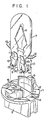
- Figure 1 is a disassembled perspective view,
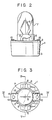
- Figure 2 is a side view,
- Figure 3 is a plan view,
- Figure 4 is a sectional view as taken along line IV-IV of Fig. 3, and
- Figure 5 is a sectional view as taken along line V-V of Fig. 3 ;
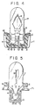
- Figure 6 is a sectional view as taken along line VI-VI of Fig. 3 ;
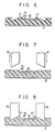
- Figures 7 and 8 are sectional views successively showing the way of the heat treatment to form a caulked portion shown in Fig. 6 ; and
- Figure 9 is a disassembled perspective view showing a baseless incandescent lamp assembly according to another embodiment of this invention.
- Now there will be described a baseless incandescent lamp according to an embodiment of this invention with reference to the accompanying drawings.
- Referring first to Figs. 1 to 6, the construction of the baseless incandescent lamp to be manufactured will be described to facilitate the understanding of the invention.
- In these figures, numeral 1 designates the main body of a lamp socket. The main lamp socket body 1, which is formed by integrally molding thermoplastic synthetic resin, includes a
circular flange section 2 and aknob section 3 on the back side of theflange section 2. Defined in the main socket body 1 is alamp holding chamber 4 opening in the front of theflange section 2. Thelamp holding chamber 4 is substantially in the form of a rectangle defined by wide front and rear sides and narrow lateral sides. A pair offitting edge sections 5 protrude from the front of theflange section 2, located around the opening of thelamp holding chamber 4. Thesefitting edge sections 5 each have an inside face with such radius of curvature that they may engage the front and rear sides of the bulb of a baseless incandescent lamp held in the socket body, thereby preventing the bulb from wobbling. Severally from the outside faces of thefitting edge sections 5 protrudestopping projections 6 spaced at a given distance from the front face of theflange section 2. When the main socket body 1 is inserted and turned in a mounting hole in a printed substrate (not shown), the mounting hole edge of the printed substrate is held between theflange section 2 and thestopping projections 6 so that the socket may be mounted on the printed substrate. - Numeral 7 designates a baseless incandescent lamp which has a
flattened seal section 9 formed by flattening the bottom portion of a cylindrical bulb and a filament 8 contained in the bulb. Theflattened seal section 9 of the baselessincandescent lamp 7 is divided into left and right portions 9b and 9c by an exhaust tube 9a.Holding members 10 are attached severally to the left and right portions 9b and 9c. Theseholding members 10 are formed by pressing a brass plate, each having a facing pair ofpinch strips 11 and acontact strip 12 which is bent substantially at right angles to the pinch strips and stretched therebetween to couple the same. Thepinch strips 11 habe at their middle portions their respective pinch sections inwardly bent so as to approach each other. Thus, the baselessincandescent lamp 7 inserted between thesepinch strips 11 has the left and right portions 9b and 9c of itsflattened seal section 9 held severally between the pinch sections of the twopinch strips 11 by the spring action thereof. To ensure such holding,engaging grooves 13 are formed respectively at the basal parts of the front and rear sides of theflattened seal section 9 so that the pinch sections of thepinch strips 11 may be fitted in thegrooves 13. Theholding members 10 have a common open bottom side, and alead wire notch 14 extends upward from the bottom end of eachcontact strip 12. A pair ofexternal lead wires 15 of the baselessincandescent lamp 7 have their one ends electrically connected with the filament 8 and the other ends passing through the left and right seal portions 9b and 9c and extended from the bottom ends thereof to the outside. The outwardly extendedexternal lead wire 15 are doubled and bent respectively toward both flanks of the baselessincandescent lamp 7. The tip end of each doubledlead wire 15 is bent upward at a point where it outwardly passes through thenotch 14 of itscorresponding contact strip 12, and extends along the outside face of thecontact strip 12. Hereupon, thecontact strip 12 may be in contact with or kept apart from the bent tip end portion of the doubledlead wire 15. Theflattened seal section 9 of the baselessincandescent lamp 7 and the pair ofholding members 10 pinching theflattened sealing section 9 therebetween are inserted in thelamp holding chamber 4 of the main socket body 1. The dimensions of thelamp holding chamber 4 are such that no substantial gap may be left between the outer peripheral surfaces of thepaired holding members 10 holding theflattened seal section 9 and the inner peripheral surface of theholding chamber 4. Namely, the width of theholding chamber 4 is a little greater than the distance between therespective contact strips 12 of the twoholding members 10, and the depth of thechamber 4 is a little greater than the distance between thepinch strips 11 of eachholding member 10. As a result, the end portion of eachexternal lead wire 15 extending along the outside face of thecontact strip 12 of itscorresponding holding member 10 inserted in thelamp holding chamber 4 is held between the outside face of thecontact strip 12 and the inside wall of theholding chamber 4, so that the electrical contact between the end portion of thelead wire 15 and theholding member 10 is secured. - The top portions of the
contact strips 12 are bent so as to be severally fitted in a pair ofgrooves 16 which are formed in the front of theflange section 2 of the main socket body 1, extending in the radial direction of theflange section 2. The top end portions of thecontact strips 12 are projected a little ahead of the front of theflange section 2 so that they may elastically abut against power supply terminals of the printed substrate to be supplied with power when the main socket body 1 is mounted on the printed substrate. Respectively formed on both sides of the basal parts of thegrooves 16 are caulkedportions 17 which project on both side edges of thecontact strips 12 to prevent theholding members 10 from slipping off the socket body. - The
caulked portion 17 may be easily made by the following manner. - There is firstly prepared an ultrasonic oscillator having four
projections 18 corresponding to both sides of the basal parts of the pair ofgrooves 16 of theflange section 2, the tip ends of theseprojections 18 being upwardly inclined toward the center lines of thegrooves 16 as shown in Fig. 7. The inclined end portions of theprojections 18 are pressed against both sides of thegrooves 16 to heat and soften the same. Then, as the inclined end portions of theprojections 18 are forced into theflange section 2, softened resin is pushed toward thegrooves 16 to be projected onto the top of thecontact strips 12, thereby forming thecaulked portions 17, as shown in Fig. 8. The projectedcaulked portions 17 enable theholding members 10 to be fixedly held in the main socket body 1 and prevented from slipping off the socket body. - In the above-described assembly the
portions 17 are formed by deforming the main socket body 1 by means of heat treatment, thereby preventing theholding members 10 from slipping out of the socket body 1. Instead, theholding member 10 may be secured to the socket body 1 by another means, which will be described with reference to Fig. 9 wherein like and same parts are denoted by the same numerals as used in Fig. 1. - As shown in Fig. 9, a
holding member 10 has acontact strip 12 which has twoprotrusions 19 integral with thestrip 12 and extending in the opposite directions from the sides of thestrip 12. The distance between the free ends of theprotrusions 19 is slightly longer than alamp holding chamber 4 is broad. The lower side of eachprotrusion 19 is tapered so that theprotrusion 19 is gradually slender toward its free end. When theholding member 10 of such structure as shown in Fig. 9 is pushed into thelamp holding chamber 4 of a main socket body 1, theprotrusions 19 bite respectively into the front and back walls which define thechamber 4. As a result, theholding member 10 is held immovable by the main socket body 1. - Alternatively, the holding
member 10 and the main socket body 1 may be connected to each other by means of an adhesive. - In the baseless incandescent lamp assembly as described above, the external lead wires are securely held between the holding members and the inner peripheral walls of the lamp holding chamber, so that there is no possibility of defective contact. The electrical connection between the external lead wires and the holding members is not limited to the case of the above-mentioned embodiment in which is obtained the hold of the lead wires between the contact strips of the holding members and the inner peripheral walls of the main socket body, and such connection may also be obtained holding the lead wires between the pinch strips and the inner peripheral walls, for example.
Claims (4)
Applications Claiming Priority (2)
| Application Number | Priority Date | Filing Date | Title |
|---|---|---|---|
| JP16598479A JPS5688274A (en) | 1979-12-20 | 1979-12-20 | Light source |
| JP165984/79 | 1979-12-20 |
Publications (4)
| Publication Number | Publication Date |
|---|---|
| EP0031069A2 EP0031069A2 (en) | 1981-07-01 |
| EP0031069A3 EP0031069A3 (en) | 1981-11-25 |
| EP0031069B1 EP0031069B1 (en) | 1984-03-21 |
| EP0031069B2 true EP0031069B2 (en) | 1986-12-30 |
Family
ID=15822708
Family Applications (1)
| Application Number | Title | Priority Date | Filing Date |
|---|---|---|---|
| EP80107732A Expired EP0031069B2 (en) | 1979-12-20 | 1980-12-08 | A baseless incandescent lamp assembly |
Country Status (5)
| Country | Link |
|---|---|
| US (1) | US4473770A (en) |
| EP (1) | EP0031069B2 (en) |
| JP (1) | JPS5688274A (en) |
| CA (1) | CA1145810A (en) |
| DE (1) | DE3067207D1 (en) |
Families Citing this family (37)
| Publication number | Priority date | Publication date | Assignee | Title |
|---|---|---|---|---|
| US4610497A (en) * | 1982-10-19 | 1986-09-09 | Nippon Seiki Kabushiki Kaisha | Lamp socket device |
| DE3400449A1 (en) * | 1984-01-09 | 1985-07-18 | Philips Patentverwaltung Gmbh, 2000 Hamburg | ELECTRIC LAMP WITH CRUSH FOOT STORED IN A SOCKET-BASED BASE |
| EP0152649A1 (en) * | 1984-01-09 | 1985-08-28 | Koninklijke Philips Electronics N.V. | Electrical lamp having a lamp cap of synthetic material |
| WO1985004769A1 (en) * | 1984-04-09 | 1985-10-24 | Nigg Juerg | Process for releasibly connecting electric lighting apparatuses, adapter respectively ballast and circuit with a high frequency generator |
| JPH0346471Y2 (en) * | 1984-09-27 | 1991-10-01 | ||
| US4623958A (en) | 1985-01-15 | 1986-11-18 | Gte Products Corporation | Replaceable automobile headlight lamp unit |
| US4569005A (en) * | 1985-01-15 | 1986-02-04 | Gte Products Corporation | Replaceable lamp unit and automobile headlight utilizing same |
| US4569006A (en) * | 1985-01-15 | 1986-02-04 | Gte Products Corporation | Replaceable lamp unit and automobile headlight utilizing same |
| JPH0314788Y2 (en) * | 1986-02-24 | 1991-04-02 | ||
| US4709305A (en) * | 1986-10-03 | 1987-11-24 | General Motors Corporation | Electrical connector for headlight assembly |
| US5018992A (en) * | 1988-05-20 | 1991-05-28 | Gte Products Corporation | Wedge lamp and clip |
| US4886994A (en) * | 1988-11-01 | 1989-12-12 | Ragge Jr Albert J | Snap-in light bulb |
| US5029057A (en) * | 1989-11-20 | 1991-07-02 | Gte Products Corporation | Clipped together lamp base |
| US4968270A (en) * | 1989-11-27 | 1990-11-06 | Molex Incorporated | Spring bulb socket |
| FR2669773B1 (en) * | 1990-11-26 | 1993-01-08 | Socop Sa | SIGNALING LAMP AND MANUFACTURING METHOD THEREOF. |
| CA2082764C (en) * | 1991-12-09 | 2002-06-04 | Guenter E. Talmon-Gros | Light bulb filament dampening system |
| JPH0553173U (en) * | 1991-12-17 | 1993-07-13 | ハリソン電機株式会社 | Small light bulb device |
| US5130911A (en) * | 1991-12-23 | 1992-07-14 | Gte Products Corporation | Two piece lamp holder |
| US5276379A (en) * | 1992-02-18 | 1994-01-04 | Gte Products Corporation | Arc discharge lamp having cementless base members |
| ES2095712T3 (en) * | 1993-03-31 | 1997-02-16 | Philips Electronics Nv | ELECTRIC LAMP. |
| DE69500937T2 (en) * | 1994-02-18 | 1998-06-10 | Sumitomo Wiring Systems | Lamp holder |
| CA2215068C (en) * | 1996-01-11 | 2004-12-28 | Patent-Treuhand-Gesellschaft Fuer Elektrische Gluehlampen Mbh | Electric lamp with uncemented base |
| DE29616116U1 (en) * | 1996-09-16 | 1996-12-12 | Patent-Treuhand-Gesellschaft für elektrische Glühlampen mbH, 81543 München | Electric lamp |
| US5696424A (en) * | 1996-09-26 | 1997-12-09 | Osram Sylvania Inc. | Alignment structure for headlamp capsule |
| US5989067A (en) * | 1998-01-30 | 1999-11-23 | Lightolier | Halogen lamp pin shroud |
| DE19843506A1 (en) * | 1998-09-23 | 2000-03-30 | Patent Treuhand Ges Fuer Elektrische Gluehlampen Mbh | Electric lamp |
| US6203169B1 (en) * | 1999-06-25 | 2001-03-20 | Osram Sylvania Inc. | Lamp and method of producing same |
| US6340861B1 (en) * | 1999-09-27 | 2002-01-22 | General Electric Company | Halogen incandescent lamp with clamping saddles |
| USD486449S1 (en) | 2002-01-29 | 2004-02-10 | Bjb Gmbh & Co. Kg | Lamp socket |
| US7063555B1 (en) | 2003-05-30 | 2006-06-20 | Nate Mullen | Quick release connector for light bulb |
| US6884118B2 (en) * | 2003-06-13 | 2005-04-26 | Christiana Industries, Llc | Lead aligning terminal |
| KR100440458B1 (en) * | 2003-11-19 | 2004-07-14 | 지형권 | High intensity discharge lamp for vehicle |
| WO2008023318A2 (en) * | 2006-08-21 | 2008-02-28 | Koninklijke Philips Electronics N.V. | Lamp having a cap in clamping fit engagement with the bulb |
| WO2008039454A2 (en) * | 2006-09-25 | 2008-04-03 | Lightsources Inc. | Smooth action, spring loaded, twist locking, radial lugged safety connector for lamp |
| US7322828B1 (en) * | 2007-04-16 | 2008-01-29 | Chiang Wen Chiang | LED socket |
| US20080272695A1 (en) * | 2007-05-04 | 2008-11-06 | Osram Sylvania Inc. | Lamp capsule retainer |
| US10041657B2 (en) * | 2016-06-13 | 2018-08-07 | Rebo Lighting & Electronics, Llc | Clip unit and edge mounted light emitting diode (LED) assembly comprising a clip unit |
Family Cites Families (11)
| Publication number | Priority date | Publication date | Assignee | Title |
|---|---|---|---|---|
| NL288232A (en) * | 1963-01-28 | |||
| US3555341A (en) * | 1968-02-07 | 1971-01-12 | Wagner Electric Corp | Rear loading panel lamp assembly |
| US3783437A (en) * | 1971-10-07 | 1974-01-01 | Gen Electric | Lamp and socket for decorative string set |
| HU169187B (en) * | 1974-07-03 | 1976-10-28 | ||
| DE2605433C3 (en) * | 1976-02-12 | 1979-01-25 | Philips Patentverwaltung Gmbh, 2000 Hamburg | Electric light bulb with centering ring |
| DE7619712U1 (en) * | 1976-06-22 | 1977-12-15 | Patent-Treuhand-Gesellschaft Fuer Elektrische Gluehlampen Mbh, 8000 Muenchen | DWARF GLOW BULB |
| IT1075495B (en) * | 1977-04-21 | 1985-04-22 | Vimercati Off Mec | MINIATURIZED BULB-LAMPHOLDER COMPLEX |
| US4100448A (en) * | 1977-05-02 | 1978-07-11 | General Electric Company | Lamp and socket assembly |
| JPS5737913Y2 (en) * | 1978-04-04 | 1982-08-20 | ||
| US4146814A (en) * | 1978-05-01 | 1979-03-27 | General Electric Company | Pinch and base structure for single-ended lamps |
| GB1602527A (en) * | 1978-05-30 | 1981-11-11 | Ford Motor Co | Bulbholder and filter assembly |
-
1979
- 1979-12-20 JP JP16598479A patent/JPS5688274A/en active Pending
-
1980
- 1980-12-08 DE DE8080107732T patent/DE3067207D1/en not_active Expired
- 1980-12-08 EP EP80107732A patent/EP0031069B2/en not_active Expired
- 1980-12-19 CA CA000367263A patent/CA1145810A/en not_active Expired
-
1983
- 1983-06-27 US US06/508,423 patent/US4473770A/en not_active Expired - Fee Related
Also Published As
| Publication number | Publication date |
|---|---|
| EP0031069A2 (en) | 1981-07-01 |
| US4473770A (en) | 1984-09-25 |
| JPS5688274A (en) | 1981-07-17 |
| EP0031069B1 (en) | 1984-03-21 |
| EP0031069A3 (en) | 1981-11-25 |
| DE3067207D1 (en) | 1984-04-26 |
| CA1145810A (en) | 1983-05-03 |
Similar Documents
| Publication | Publication Date | Title |
|---|---|---|
| EP0031069B2 (en) | A baseless incandescent lamp assembly | |
| US4365396A (en) | Method for manufacturing a baseless incandescent lamp assembly | |
| US4152622A (en) | Lamp-base assembly | |
| US3017599A (en) | Lamp socket | |
| US4114972A (en) | Wedge base bulb socket | |
| US4593958A (en) | Socket for baseless lamp | |
| US2892992A (en) | Printed circuit lamp base | |
| US4367573A (en) | Method for manufacturing a baseless incandescent lamp assembly | |
| US4752241A (en) | L-shaped bulb socket | |
| US4595859A (en) | Halogen incandescent lamp and socket combination, particularly for direct assembly into a fixture with bayonet lock | |
| US4468585A (en) | Wedge base lamp socket | |
| EP0023717B1 (en) | Socket for capless incandescent lamp | |
| US3339172A (en) | Electric lampholder | |
| US5229683A (en) | Electric lamp with cementless base | |
| US3206713A (en) | Lamp having resilient terminals | |
| US3060401A (en) | Indicator light assembly | |
| US4837479A (en) | Electric lamp with insulating base | |
| GB2029093A (en) | Attachment of caps to press- sealed lamps | |
| US3430189A (en) | Recessed double contact pin base | |
| US3533050A (en) | Electrical socket | |
| US3892463A (en) | Snap-latching, snap-lighting electric lamps and methods for making same | |
| JP3462239B2 (en) | Socket device and display device | |
| JPH0247586Y2 (en) | ||
| KR200143170Y1 (en) | Automotive Lamp Socket Assembly | |
| KR900001202Y1 (en) | Neo wedge base for indicator lamp |
Legal Events
| Date | Code | Title | Description |
|---|---|---|---|
| PUAI | Public reference made under article 153(3) epc to a published international application that has entered the european phase |
Free format text: ORIGINAL CODE: 0009012 |
|
| 17P | Request for examination filed |
Effective date: 19801208 |
|
| AK | Designated contracting states |
Designated state(s): CH DE FR GB IT LI NL |
|
| PUAL | Search report despatched |
Free format text: ORIGINAL CODE: 0009013 |
|
| AK | Designated contracting states |
Designated state(s): CH DE FR GB IT LI NL |
|
| ITF | It: translation for a ep patent filed | ||
| GRAA | (expected) grant |
Free format text: ORIGINAL CODE: 0009210 |
|
| AK | Designated contracting states |
Designated state(s): CH DE FR GB IT LI NL |
|
| REF | Corresponds to: |
Ref document number: 3067207 Country of ref document: DE Date of ref document: 19840426 |
|
| ET | Fr: translation filed | ||
| RAP2 | Party data changed (patent owner data changed or rights of a patent transferred) |
Owner name: KABUSHIKI KAISHA TOSHIBA |
|
| PLBI | Opposition filed |
Free format text: ORIGINAL CODE: 0009260 |
|
| REG | Reference to a national code |
Ref country code: FR Ref legal event code: CD |
|
| 26 | Opposition filed |
Opponent name: N.V. PHILIPS' GLOEILAMPENFABRIEKEN Effective date: 19841206 |
|
| NLR1 | Nl: opposition has been filed with the epo |
Opponent name: N.V. PHILIPS' GLOEILAMPENFABRIEKEN |
|
| REG | Reference to a national code |
Ref country code: GB Ref legal event code: 746 |
|
| PUAH | Patent maintained in amended form |
Free format text: ORIGINAL CODE: 0009272 |
|
| STAA | Information on the status of an ep patent application or granted ep patent |
Free format text: STATUS: PATENT MAINTAINED AS AMENDED |
|
| 27A | Patent maintained in amended form |
Effective date: 19861230 |
|
| AK | Designated contracting states |
Kind code of ref document: B2 Designated state(s): CH DE FR GB IT LI NL |
|
| ITF | It: translation for a ep patent filed | ||
| ET3 | Fr: translation filed ** decision concerning opposition | ||
| NLR2 | Nl: decision of opposition | ||
| NLR3 | Nl: receipt of modified translations in the netherlands language after an opposition procedure | ||
| ITTA | It: last paid annual fee | ||
| PGFP | Annual fee paid to national office [announced via postgrant information from national office to epo] |
Ref country code: GB Payment date: 19911126 Year of fee payment: 12 |
|
| PGFP | Annual fee paid to national office [announced via postgrant information from national office to epo] |
Ref country code: FR Payment date: 19911209 Year of fee payment: 12 |
|
| PGFP | Annual fee paid to national office [announced via postgrant information from national office to epo] |
Ref country code: CH Payment date: 19911218 Year of fee payment: 12 |
|
| PGFP | Annual fee paid to national office [announced via postgrant information from national office to epo] |
Ref country code: NL Payment date: 19911231 Year of fee payment: 12 |
|
| PGFP | Annual fee paid to national office [announced via postgrant information from national office to epo] |
Ref country code: DE Payment date: 19920131 Year of fee payment: 12 |
|
| PG25 | Lapsed in a contracting state [announced via postgrant information from national office to epo] |
Ref country code: GB Effective date: 19921208 |
|
| PG25 | Lapsed in a contracting state [announced via postgrant information from national office to epo] |
Ref country code: LI Effective date: 19921231 Ref country code: CH Effective date: 19921231 |
|
| PG25 | Lapsed in a contracting state [announced via postgrant information from national office to epo] |
Ref country code: NL Effective date: 19930701 |
|
| GBPC | Gb: european patent ceased through non-payment of renewal fee |
Effective date: 19921208 |
|
| NLV4 | Nl: lapsed or anulled due to non-payment of the annual fee | ||
| PG25 | Lapsed in a contracting state [announced via postgrant information from national office to epo] |
Ref country code: FR Effective date: 19930831 |
|
| REG | Reference to a national code |
Ref country code: CH Ref legal event code: PL |
|
| PG25 | Lapsed in a contracting state [announced via postgrant information from national office to epo] |
Ref country code: DE Effective date: 19930901 |
|
| REG | Reference to a national code |
Ref country code: FR Ref legal event code: ST |