EP0030428B1 - Apparatus for transporting metal in coiled form - Google Patents
Apparatus for transporting metal in coiled form Download PDFInfo
- Publication number
- EP0030428B1 EP0030428B1 EP80304218A EP80304218A EP0030428B1 EP 0030428 B1 EP0030428 B1 EP 0030428B1 EP 80304218 A EP80304218 A EP 80304218A EP 80304218 A EP80304218 A EP 80304218A EP 0030428 B1 EP0030428 B1 EP 0030428B1
- Authority
- EP
- European Patent Office
- Prior art keywords
- support
- coil
- trolley
- coils
- supports
- Prior art date
- Legal status (The legal status is an assumption and is not a legal conclusion. Google has not performed a legal analysis and makes no representation as to the accuracy of the status listed.)
- Expired
Links
Images

Classifications
-
- B—PERFORMING OPERATIONS; TRANSPORTING
- B21—MECHANICAL METAL-WORKING WITHOUT ESSENTIALLY REMOVING MATERIAL; PUNCHING METAL
- B21C—MANUFACTURE OF METAL SHEETS, WIRE, RODS, TUBES, PROFILES OR LIKE SEMI-MANUFACTURED PRODUCTS OTHERWISE THAN BY ROLLING; AUXILIARY OPERATIONS USED IN CONNECTION WITH METAL-WORKING WITHOUT ESSENTIALLY REMOVING MATERIAL
- B21C47/00—Winding-up, coiling or winding-off metal wire, metal band or other flexible metal material characterised by features relevant to metal processing only
- B21C47/24—Transferring coils to or from winding apparatus or to or from operative position therein; Preventing uncoiling during transfer
-
- Y—GENERAL TAGGING OF NEW TECHNOLOGICAL DEVELOPMENTS; GENERAL TAGGING OF CROSS-SECTIONAL TECHNOLOGIES SPANNING OVER SEVERAL SECTIONS OF THE IPC; TECHNICAL SUBJECTS COVERED BY FORMER USPC CROSS-REFERENCE ART COLLECTIONS [XRACs] AND DIGESTS
- Y10—TECHNICAL SUBJECTS COVERED BY FORMER USPC
- Y10S—TECHNICAL SUBJECTS COVERED BY FORMER USPC CROSS-REFERENCE ART COLLECTIONS [XRACs] AND DIGESTS
- Y10S414/00—Material or article handling
- Y10S414/124—Roll handlers
Definitions
- This invention relates to apparatus for transporting metal in coiled form.
- the coils may be suspended from an overhead conveyor with the opening through the coil arranged substantially horizontal and with a conveyor support projecting through the opening so that a support surface engages the inner periphery of the coil.
- the coil may be transported, with the coil opening arranged substantially horizontal, on a transporter car.
- a support surface on the car engages the outer periphery of the coil. It is to a transporter car of this latter type that the present invention is particularly concerned.
- FR-A-2297176 discloses a transporter car for displacing coils of metal.
- the car comprises a wheeled trolley which is displaceable along a track.
- the trolley provides one support for receiving a coil by engaging its periphery to support the coil with the longitudinal axis of the coil opening arranged in the direction of movement of the trolley.
- the support consists of two pairs of levers arranged transverse to the direction of movement of the trolley, the two pairs of levers do not, in themselves, act as supports but are joined together by longitudinally extending plates. Means are provided for rotating the levers together so that the plates are raised and lowered together to displace a coil supported on them.
- a transporter car may be dimensioned so as to support coils of a particular fixed axial length, but in many applications the transporter car has to support coils of different axial lengths. If the transporter car has a support surface which is capable of supporting coils of the maximum length to be transported, then problems can occur when coils of less than the maximum axial length are supported on the transporter car. The main problem is concerned with removing coils from the transporter so that they are arranged on a support trestle in end-to-end abutting relation.
- a transporter car for carrying a coil of metal comprises a wheeled trolley, a first fixed support on the trolley for engaging the periphery of a coil to provide a support for the coil, a second support on the trolley for engaging the periphery of a coil to provide a support for the coil, said first and second supports being arranged side-by-side in the direction of movement of the trolley and the second support being displaceable between two positions in which the level of the second support is the same as that of the first support and below that of the first support respectively.
- the total axial length of the first and second supports is arranged to be slightly less than the axial length of the maximum sized coils which are to be transported so that, when one of these coils is supported on the two supports, an end portion of the coil projects beyond the supports.
- the second support is displaced to a position where it does not support the coil and the first support is arranged to support the coil.
- the axial length of the first support is chosen to be less than the axial length of the smallest coils to be transported.
- the second support conveniently includes a toggle mechanism by which the positions of the support level relative to the first support can be adjusted.
- apparatus for forming a pack of coils of metal rod comprises a C-hook 1 suspended from and movable along an overhead gantry 2, a transporter car 4 and a support trestle 6.
- the support trestle comprises a pair of stationary support plates 8 arranged in horizontal spaced apart relation.
- a fixed support plate 11 is at one end of the trestle and the plate provides a surface 12 which is inclined rearwardly from the support plate.
- a beam structure 13 extends from a position beneath an unloading position of the C-hook 1 to a position beneath the support trestle.
- a track 14 is mounted on the beam structure.
- a plurality of pivoted bell crank levers 15 are spaced apart along the length of the beam structure and the levers are connected together by rods 16 which are coupled to a piston-cylinder device 17. On operating the device 17, the beam structure and the track 14 are raised and lowered by the bell crank levers.
- the coil transporter 4 comprises a trolley on wheels 19 which are on the track 14.
- the transporter provides first and second supports 20 and 21 respectively for supporting a coil 22 of rod.
- the support 20 comprises three spaced apart plates 23 secured to the trolley and carrying a pair of support members 24 which extend horizontally and are engageable with the periphery of the coil.
- the second support 21 is retractable so that it can be used in combination with support 20 for long coils but can be retracted into a position where it is not used when shorter coils are to be supported.
- a pair of arms 26 are pivotable about the trolley and carry a support pad 27 extending in the direction of movement of the trolley.
- An arm 28 positioned between the arms 26 carries a support pad 29 and is pivotable about a pivot 30 on the trolley.
- a linkage 31 includes a two-part toggle pivoted to the trolley at 32 and to the arm 28.
- the linkage also includes a roller 33 which abuts against the underside of the arm 26.
- the lower end of the toggle linkage is connected to the piston of a piston-cylinder assembly 34.
- the toggle linkage In the position shown in full lines in Figure 3, the toggle linkage is straight and the arms 26 and 28 are elevated.
- the support surfaces of the pads 27, 29 are at the same level as the support surfaces of the pads 24 of the first support 20.
- the toggle linkage On operating the piston-cylinder assembly, the toggle linkage is broken, lowering arms 26 and 28 to the positions shown in broken lines.
- a coil 22 is brought to the loading station on a C-hook 1 and is positioned above the trolley 4.
- the actuating device 17 is actuated to cause the beam 7 to be raised, thereby raising the track 14 and the trolley 4 until the weight of the coil is taken on the supports 20, 21.
- the trolley is then traversed forward to take with it the coil 22 from the hook 1 and move the coil, with its longitudinal axis substantially horizontal, to the support trestle 6.
- the trolley continues to move forward until the coil engages against the inclined surface 12.
- the trolley is then stopped and the actuating device 17 causes the trolley to be lowered, thereby depositing the coil on the support 6 with the coil leaning forward against the inclined support surface 12.
- the weight of the coil is thus taken off the trolley which is free to be moved back to the loading station.
- a second coil is then supported on the trolley in the manner described above and this second coil is traversed forward on to the support 6 until the coil abuts against the previously deposited coil on the support.
- the trolley is then lowered so that the coil remains supported on the support abutting against the previously deposited coil. This is repeated until a plurality, say three coils, are similarly supported on the support, each leaning forward in the direction away from the loading station.
- the packs of coils so formed can then be removed from the support by an overhead crane or the like and the coils making up the pack can be secured together by fastening means extending around the pack of coils.
- the trolley is conveniently provided with an upstanding flap 30 which is lowered during its direction of movement from the support 6 to the loading station but is thereafter raised and, as the trolley is moved forward beneath the coil supported on the hook 1, the flap 30 abuts against the coil to indicate that the trolley is beneath the coil.
- a signal from the flap causes the movement of the trolley to be stopped.
- the flap also causes the coil to be tilted slightly on the C-hook ' so that it can readily be removed from the hook.
- support 21 is retracted and the support 24 serves to support the coil when it is supported on the trolley, but for coils of longer length, the support 21 is raised so that the coil is supported on supports 24 and 21.
- the length of support 24 is arranged to be less than the length of the minimum length of coil to be transported and the total length of supports 21 and 24 is arranged to be less than the maximum length of coil to be transported so that, when a coil is carried on the transporter car, it has a portion which projects forward of the support(s).
Landscapes
- Engineering & Computer Science (AREA)
- Mechanical Engineering (AREA)
- Winding, Rewinding, Material Storage Devices (AREA)
- Reciprocating Conveyors (AREA)
- Discharge Of Articles From Conveyors (AREA)
- Chain Conveyers (AREA)
- Replacement Of Web Rolls (AREA)
- Wire Processing (AREA)
Abstract
Description
- This invention relates to apparatus for transporting metal in coiled form.
- In the metal forming art, it is well known to coil the metal, whether it is rod or strip, ready for further processing. It is also well known for the coils to be bound so that they cannot readily come apart and then to be transported from place to place.
- The coils may be suspended from an overhead conveyor with the opening through the coil arranged substantially horizontal and with a conveyor support projecting through the opening so that a support surface engages the inner periphery of the coil. Alternatively, the coil may be transported, with the coil opening arranged substantially horizontal, on a transporter car. A support surface on the car engages the outer periphery of the coil. It is to a transporter car of this latter type that the present invention is particularly concerned.
- FR-A-2297176 discloses a transporter car for displacing coils of metal. The car comprises a wheeled trolley which is displaceable along a track. The trolley provides one support for receiving a coil by engaging its periphery to support the coil with the longitudinal axis of the coil opening arranged in the direction of movement of the trolley. Although the support consists of two pairs of levers arranged transverse to the direction of movement of the trolley, the two pairs of levers do not, in themselves, act as supports but are joined together by longitudinally extending plates. Means are provided for rotating the levers together so that the plates are raised and lowered together to displace a coil supported on them.
- A transporter car may be dimensioned so as to support coils of a particular fixed axial length, but in many applications the transporter car has to support coils of different axial lengths. If the transporter car has a support surface which is capable of supporting coils of the maximum length to be transported, then problems can occur when coils of less than the maximum axial length are supported on the transporter car. The main problem is concerned with removing coils from the transporter so that they are arranged on a support trestle in end-to-end abutting relation. When a first coil is present on the trestle and a second coil is transported on a car to the trestle, unless the end of the second coil which is adjacent the trestle projects beyond the support surface, the second coil cannot be positioned from the transporter car directly on to the trestle in abutting relation with the first coil. This is because the end of the support surface which is ahead of the coil abuts against the first coil and, when the second coil is deposited on the trestle, there is a space between the two coils. When a number of coils of metal rod are being positioned on the trestle support prior to them being formed into a pack, it is undesirable for there to be spaces between adjacent coils.
- It is an object of the present invention to provide a transporter car in which the support surface is of adjustable length.
- According to the present invention, a transporter car for carrying a coil of metal comprises a wheeled trolley, a first fixed support on the trolley for engaging the periphery of a coil to provide a support for the coil, a second support on the trolley for engaging the periphery of a coil to provide a support for the coil, said first and second supports being arranged side-by-side in the direction of movement of the trolley and the second support being displaceable between two positions in which the level of the second support is the same as that of the first support and below that of the first support respectively.
- The total axial length of the first and second supports is arranged to be slightly less than the axial length of the maximum sized coils which are to be transported so that, when one of these coils is supported on the two supports, an end portion of the coil projects beyond the supports. For transporting smaller sized coils, the second support is displaced to a position where it does not support the coil and the first support is arranged to support the coil. The axial length of the first support is chosen to be less than the axial length of the smallest coils to be transported.
- The second support conveniently includes a toggle mechanism by which the positions of the support level relative to the first support can be adjusted.
- In order that the invention may be more readily understood it will now be described, by way of example only, with reference to the accompanying drawings, in which:-
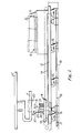
- Figure 1 is a side elevation of apparatus for arranging coils of metal rod in a pack and including apparatus in accordance with the present invention,
- Figure 2 is a section on the line B-B of Figure 1, and
- Figure 3 is a section on the line A-A of Figure 1.
- Referring to Figure 1, apparatus for forming a pack of coils of metal rod comprises a C-
hook 1 suspended from and movable along an overhead gantry 2, atransporter car 4 and a support trestle 6. - The support trestle comprises a pair of stationary support plates 8 arranged in horizontal spaced apart relation. A fixed support plate 11 is at one end of the trestle and the plate provides a
surface 12 which is inclined rearwardly from the support plate. - A
beam structure 13 extends from a position beneath an unloading position of the C-hook 1 to a position beneath the support trestle. Atrack 14 is mounted on the beam structure. A plurality of pivotedbell crank levers 15 are spaced apart along the length of the beam structure and the levers are connected together byrods 16 which are coupled to a piston-cylinder device 17. On operating thedevice 17, the beam structure and thetrack 14 are raised and lowered by the bell crank levers. - The
coil transporter 4 comprises a trolley onwheels 19 which are on thetrack 14. The transporter provides first andsecond supports coil 22 of rod. Thesupport 20 comprises three spaced apartplates 23 secured to the trolley and carrying a pair ofsupport members 24 which extend horizontally and are engageable with the periphery of the coil. Thesecond support 21 is retractable so that it can be used in combination withsupport 20 for long coils but can be retracted into a position where it is not used when shorter coils are to be supported. - Referring particularly to Figure 3, a pair of
arms 26 are pivotable about the trolley and carry asupport pad 27 extending in the direction of movement of the trolley. Anarm 28 positioned between thearms 26 carries asupport pad 29 and is pivotable about apivot 30 on the trolley. - A
linkage 31 includes a two-part toggle pivoted to the trolley at 32 and to thearm 28. The linkage also includes aroller 33 which abuts against the underside of thearm 26. The lower end of the toggle linkage is connected to the piston of a piston-cylinder assembly 34. In the position shown in full lines in Figure 3, the toggle linkage is straight and thearms pads pads 24 of thefirst support 20. On operating the piston-cylinder assembly, the toggle linkage is broken, loweringarms - In use, a
coil 22 is brought to the loading station on a C-hook 1 and is positioned above thetrolley 4. The actuatingdevice 17 is actuated to cause the beam 7 to be raised, thereby raising thetrack 14 and thetrolley 4 until the weight of the coil is taken on thesupports coil 22 from thehook 1 and move the coil, with its longitudinal axis substantially horizontal, to the support trestle 6. The trolley continues to move forward until the coil engages against theinclined surface 12. The trolley is then stopped and the actuatingdevice 17 causes the trolley to be lowered, thereby depositing the coil on the support 6 with the coil leaning forward against theinclined support surface 12. The weight of the coil is thus taken off the trolley which is free to be moved back to the loading station. A second coil is then supported on the trolley in the manner described above and this second coil is traversed forward on to the support 6 until the coil abuts against the previously deposited coil on the support. The trolley is then lowered so that the coil remains supported on the support abutting against the previously deposited coil. This is repeated until a plurality, say three coils, are similarly supported on the support, each leaning forward in the direction away from the loading station. The packs of coils so formed can then be removed from the support by an overhead crane or the like and the coils making up the pack can be secured together by fastening means extending around the pack of coils. - The trolley is conveniently provided with an
upstanding flap 30 which is lowered during its direction of movement from the support 6 to the loading station but is thereafter raised and, as the trolley is moved forward beneath the coil supported on thehook 1, theflap 30 abuts against the coil to indicate that the trolley is beneath the coil. A signal from the flap causes the movement of the trolley to be stopped. The flap also causes the coil to be tilted slightly on the C-hook 'so that it can readily be removed from the hook. - Thus, for coils of short length,
support 21 is retracted and thesupport 24 serves to support the coil when it is supported on the trolley, but for coils of longer length, thesupport 21 is raised so that the coil is supported onsupports support 24 is arranged to be less than the length of the minimum length of coil to be transported and the total length ofsupports
Claims (4)
Priority Applications (1)
| Application Number | Priority Date | Filing Date | Title |
|---|---|---|---|
| AT80304218T ATE8113T1 (en) | 1979-11-30 | 1980-11-25 | DEVICE FOR TRANSPORTING METAL IN ROLLED FORM. |
Applications Claiming Priority (2)
| Application Number | Priority Date | Filing Date | Title |
|---|---|---|---|
| GB7941416 | 1979-11-30 | ||
| GB7941416 | 1979-11-30 |
Publications (2)
| Publication Number | Publication Date |
|---|---|
| EP0030428A1 EP0030428A1 (en) | 1981-06-17 |
| EP0030428B1 true EP0030428B1 (en) | 1984-06-27 |
Family
ID=10509527
Family Applications (1)
| Application Number | Title | Priority Date | Filing Date |
|---|---|---|---|
| EP80304218A Expired EP0030428B1 (en) | 1979-11-30 | 1980-11-25 | Apparatus for transporting metal in coiled form |
Country Status (5)
| Country | Link |
|---|---|
| US (1) | US4367059A (en) |
| EP (1) | EP0030428B1 (en) |
| JP (1) | JPS5693620A (en) |
| AT (1) | ATE8113T1 (en) |
| DE (1) | DE3068382D1 (en) |
Cited By (1)
| Publication number | Priority date | Publication date | Assignee | Title |
|---|---|---|---|---|
| CN104084450A (en) * | 2014-07-14 | 2014-10-08 | 大连华锐重工集团股份有限公司 | Side push plate device of cold rolling copper belt recoiling machine |
Families Citing this family (17)
| Publication number | Priority date | Publication date | Assignee | Title |
|---|---|---|---|---|
| US4744708A (en) * | 1985-03-25 | 1988-05-17 | Cochrane Steel Products (Proprietary) Limited | Coil member restraining barrier and carrying vehicle |
| DE4106491A1 (en) * | 1991-03-01 | 1992-09-03 | Schloemann Siemag Ag | SYSTEM WITH A FEDERAL PICTURE AND TRANSPORT SYSTEM FOR WIRE OR FINE STEEL, ESPECIALLY FOR HIGH FELT WEIGHTS |
| IT1253922B (en) * | 1991-12-20 | 1995-08-31 | Gd Spa | TROLLEY FOR LOADING REELS INTO A FEEDING DEVICE OF A PACKAGING MACHINE |
| US5674049A (en) * | 1994-06-17 | 1997-10-07 | Automatic Handling, Inc. | Roll handling apparatus |
| US5533859A (en) * | 1994-06-17 | 1996-07-09 | Automatic Handling, Inc. | Roll handling apparatus |
| US6415904B1 (en) | 1997-11-25 | 2002-07-09 | James S. Markiewicz | Shuttle car conveyor for conveyable material |
| US6223885B1 (en) * | 1997-11-25 | 2001-05-01 | Captial Engineering, Inc. | Shuttle car conveyor for conveyable material |
| US6077005A (en) * | 1997-11-28 | 2000-06-20 | Trinity Industries, Inc. | Vehicle with collapsible platform |
| US6739268B2 (en) | 2000-12-15 | 2004-05-25 | National Steel Car Ltd | Multiple trough coil car |
| US6637990B2 (en) * | 2000-12-15 | 2003-10-28 | National Steel Car Limited | Coil car with internal walkway |
| US6579048B2 (en) * | 2000-12-15 | 2003-06-17 | Nat Steel Car Ltd | Coil stop for rail road coil car |
| US6505564B2 (en) * | 2001-05-23 | 2003-01-14 | National Steel Car Limited | Well car with cross member |
| US6749381B2 (en) | 2001-10-12 | 2004-06-15 | National Steel Car Limited | Retractable coil stop mechanism for railroad coil car |
| US7419139B2 (en) * | 2004-07-19 | 2008-09-02 | Pavlov Michael V | Barbed tape product with a predetermined pattern of attachment points and attachment elements |
| US7290756B2 (en) * | 2004-07-19 | 2007-11-06 | Pavlov Michael V | Concertina tape products configured for stable deployment and retrieval |
| US7353576B2 (en) * | 2004-07-19 | 2008-04-08 | Pavlov Michael V | Methods for forming barbed tape product |
| CN116000213A (en) * | 2023-01-30 | 2023-04-25 | 北京巴塔科技有限公司 | Workshop coil shearing total arrangement system and shearing method |
Family Cites Families (6)
| Publication number | Priority date | Publication date | Assignee | Title |
|---|---|---|---|---|
| US3168206A (en) * | 1962-12-13 | 1965-02-02 | Nat Homes Corp | Trailer |
| US3262664A (en) * | 1964-10-30 | 1966-07-26 | Paraskewik William | Universal missile adapter |
| AT324941B (en) * | 1973-06-19 | 1975-09-25 | Voest Ag | CONVEYOR DEVICE FOR TIN COLLARS |
| US3902612A (en) * | 1973-08-16 | 1975-09-02 | Fred C Hall | Reel transport storage mechanism |
| FR2297176A1 (en) * | 1975-01-10 | 1976-08-06 | Elineau Hubert | Mechanical handling machine for metal wire coils - has trolley with pivoting support arms conveying coil to stacking area |
| DE2732977A1 (en) * | 1977-07-21 | 1979-02-01 | Mehne Fa Erwin | Transfer mechanism for containers between chain conveyors - has transfer slide on guide track adjustable for height |
-
1980
- 1980-11-24 US US06/209,517 patent/US4367059A/en not_active Expired - Lifetime
- 1980-11-25 DE DE8080304218T patent/DE3068382D1/en not_active Expired
- 1980-11-25 EP EP80304218A patent/EP0030428B1/en not_active Expired
- 1980-11-25 AT AT80304218T patent/ATE8113T1/en not_active IP Right Cessation
- 1980-12-01 JP JP16945380A patent/JPS5693620A/en active Pending
Cited By (2)
| Publication number | Priority date | Publication date | Assignee | Title |
|---|---|---|---|---|
| CN104084450A (en) * | 2014-07-14 | 2014-10-08 | 大连华锐重工集团股份有限公司 | Side push plate device of cold rolling copper belt recoiling machine |
| CN104084450B (en) * | 2014-07-14 | 2016-04-20 | 大连华锐重工集团股份有限公司 | Cold rolling copper strips batches pusher side push plate device |
Also Published As
| Publication number | Publication date |
|---|---|
| ATE8113T1 (en) | 1984-07-15 |
| DE3068382D1 (en) | 1984-08-02 |
| EP0030428A1 (en) | 1981-06-17 |
| US4367059A (en) | 1983-01-04 |
| JPS5693620A (en) | 1981-07-29 |
Similar Documents
| Publication | Publication Date | Title |
|---|---|---|
| US4367059A (en) | Variable sized coil carrying car | |
| US3710711A (en) | System for forming and handling annular rod bundles | |
| JP2584231B2 (en) | Automatic device for lining the inner wall of a container with bricks | |
| US5087166A (en) | Handling vehicle for printed product reels | |
| US3739930A (en) | Coil transporting structure | |
| US4046265A (en) | Loading and unloading bridge for containers | |
| JP3178376B2 (en) | Coil car and method of operating the coil car | |
| US2953239A (en) | Rod bundle unloader | |
| US4641512A (en) | Plant to form and cool coils | |
| US2678715A (en) | Transfer mechanism for right-angle conveyer lines | |
| US3441148A (en) | Downender for transferring coils | |
| US5037264A (en) | Hydraulically operated load handling vehicle for open-top railway cars | |
| US4108317A (en) | Continuous laying of pipes of large diameter | |
| JPH04319020A (en) | Device with bundle forming and transferring system for wire or thin steel material | |
| JP2887889B2 (en) | crane | |
| US4487547A (en) | Method for random car train positioning | |
| JPH0721244U (en) | Crop carry-out device | |
| JP2505582Y2 (en) | Waste coil discharge device | |
| US3095984A (en) | Article handling equipment | |
| JPH08188394A (en) | Working device for long materials | |
| SU1148740A2 (en) | Flow line for continuous gas cutting of sheets | |
| JPH11179474A (en) | Long object processing equipment | |
| JPS5811794Y2 (en) | Container loading/unloading bridge | |
| JP2561185Y2 (en) | Gas filling equipment | |
| SU1214547A1 (en) | Device for unloading containers |
Legal Events
| Date | Code | Title | Description |
|---|---|---|---|
| PUAI | Public reference made under article 153(3) epc to a published international application that has entered the european phase |
Free format text: ORIGINAL CODE: 0009012 |
|
| AK | Designated contracting states |
Designated state(s): AT BE CH DE FR GB IT LI LU NL SE |
|
| 17P | Request for examination filed |
Effective date: 19811127 |
|
| RAP1 | Party data changed (applicant data changed or rights of an application transferred) |
Owner name: DAVY MCKEE (SHEFFIELD) LIMITED |
|
| ITF | It: translation for a ep patent filed | ||
| GRAA | (expected) grant |
Free format text: ORIGINAL CODE: 0009210 |
|
| AK | Designated contracting states |
Designated state(s): AT BE CH DE FR GB IT LI LU NL SE |
|
| PG25 | Lapsed in a contracting state [announced via postgrant information from national office to epo] |
Ref country code: LI Effective date: 19840627 Ref country code: CH Effective date: 19840627 |
|
| REF | Corresponds to: |
Ref document number: 8113 Country of ref document: AT Date of ref document: 19840715 Kind code of ref document: T |
|
| REF | Corresponds to: |
Ref document number: 3068382 Country of ref document: DE Date of ref document: 19840802 |
|
| ET | Fr: translation filed | ||
| REG | Reference to a national code |
Ref country code: CH Ref legal event code: PL |
|
| PG25 | Lapsed in a contracting state [announced via postgrant information from national office to epo] |
Ref country code: AT Effective date: 19841125 |
|
| PG25 | Lapsed in a contracting state [announced via postgrant information from national office to epo] |
Ref country code: SE Effective date: 19841126 |
|
| PG25 | Lapsed in a contracting state [announced via postgrant information from national office to epo] |
Ref country code: LU Free format text: LAPSE BECAUSE OF NON-PAYMENT OF DUE FEES Effective date: 19841130 Ref country code: BE Effective date: 19841130 |
|
| PLBE | No opposition filed within time limit |
Free format text: ORIGINAL CODE: 0009261 |
|
| STAA | Information on the status of an ep patent application or granted ep patent |
Free format text: STATUS: NO OPPOSITION FILED WITHIN TIME LIMIT |
|
| BERE | Be: lapsed |
Owner name: DAVY MCKEE (SHEFFIELD) LTD Effective date: 19841125 |
|
| PG25 | Lapsed in a contracting state [announced via postgrant information from national office to epo] |
Ref country code: NL Effective date: 19850601 |
|
| 26N | No opposition filed | ||
| GBPC | Gb: european patent ceased through non-payment of renewal fee | ||
| NLV4 | Nl: lapsed or anulled due to non-payment of the annual fee | ||
| PG25 | Lapsed in a contracting state [announced via postgrant information from national office to epo] |
Ref country code: FR Free format text: LAPSE BECAUSE OF NON-PAYMENT OF DUE FEES Effective date: 19850731 |
|
| PG25 | Lapsed in a contracting state [announced via postgrant information from national office to epo] |
Ref country code: DE Effective date: 19850801 |
|
| REG | Reference to a national code |
Ref country code: FR Ref legal event code: ST |
|
| PG25 | Lapsed in a contracting state [announced via postgrant information from national office to epo] |
Ref country code: GB Effective date: 19881118 |
|
| EUG | Se: european patent has lapsed |
Ref document number: 80304218.3 Effective date: 19851008 |