EP0030372B1 - Electrophotographic copier - Google Patents
Electrophotographic copier Download PDFInfo
- Publication number
- EP0030372B1 EP0030372B1 EP80107615A EP80107615A EP0030372B1 EP 0030372 B1 EP0030372 B1 EP 0030372B1 EP 80107615 A EP80107615 A EP 80107615A EP 80107615 A EP80107615 A EP 80107615A EP 0030372 B1 EP0030372 B1 EP 0030372B1
- Authority
- EP
- European Patent Office
- Prior art keywords
- fuser
- temperature
- cycle
- cycles
- comparator
- Prior art date
- Legal status (The legal status is an assumption and is not a legal conclusion. Google has not performed a legal analysis and makes no representation as to the accuracy of the status listed.)
- Expired
Links
Images


Classifications
-
- G—PHYSICS
- G03—PHOTOGRAPHY; CINEMATOGRAPHY; ANALOGOUS TECHNIQUES USING WAVES OTHER THAN OPTICAL WAVES; ELECTROGRAPHY; HOLOGRAPHY
- G03G—ELECTROGRAPHY; ELECTROPHOTOGRAPHY; MAGNETOGRAPHY
- G03G15/00—Apparatus for electrographic processes using a charge pattern
- G03G15/20—Apparatus for electrographic processes using a charge pattern for fixing, e.g. by using heat
- G03G15/2003—Apparatus for electrographic processes using a charge pattern for fixing, e.g. by using heat using heat
-
- G—PHYSICS
- G05—CONTROLLING; REGULATING
- G05D—SYSTEMS FOR CONTROLLING OR REGULATING NON-ELECTRIC VARIABLES
- G05D23/00—Control of temperature
- G05D23/19—Control of temperature characterised by the use of electric means
- G05D23/1917—Control of temperature characterised by the use of electric means using digital means
-
- G—PHYSICS
- G05—CONTROLLING; REGULATING
- G05D—SYSTEMS FOR CONTROLLING OR REGULATING NON-ELECTRIC VARIABLES
- G05D23/00—Control of temperature
- G05D23/19—Control of temperature characterised by the use of electric means
- G05D23/20—Control of temperature characterised by the use of electric means with sensing elements having variation of electric or magnetic properties with change of temperature
Definitions
- the invention relates to an electrophotographic copier having an electrically heated fuser and a control apparatus for regulating the temperature of the fuser.
- an electrophotographic apparatus for example a xerographic copier
- a pattern of toner is placed on paper in accordance with an image on an original document.
- the toner is fixed on the paper to form a permanent copy of the original image by applying a combination of heat and pressure to the toner and paper.
- the paper carrying loosely adhering toner is passed between a heated fuser roll and a backup roll to essentially melt the toner into the paper.
- the quality of the result depends upon the temperature to which the paper is brought during the fusing operation. At the extremes, too high a temperature will undesirably remove toner from the paper, while too low a temperature will fail to properly bond the toner to the paper. In practical systems, a major problem is non-uniformity of heat application over the duration of a "copy run" i.e., during the copying of one or more originals in a single continuous operator-initiated job. Successive sheets of paper may reach different temperatures, not all within the acceptable range, and different sizes of paper may reach different temperatures at different times.
- a physically massive fuser roll will eventually reach a stable surface temperature which is substantially independent of external factors such as the size and quantity of paper placed in contact with it or the rate at which the paper is fed past the roller.
- copier size, energy availability and time-to-first-copy restrictions dictate that a fuser roll be as physically small as possible.
- Commercial couplers acceptable in an office environment ideally must be physically small, cannot generate excessive quantities of heat and must be connectable to a conventional electrical power outlet.
- the fuser heater is often a major source of heat and user of electrical energy, and the size of the fuser is a significant factor in the size of the copier.
- a small fuser is desirable at least because it generates less heat, uses less power, takes up less space.
- the prior art discloses a number of approaches to the problem of accurately controlling fuser temperature.
- the simplest prior art approach provides an on-off thermostat in series with the fuser heater. While this provides control of fuser temperature, on-off cycling does not give the accuracy required by compact and fast copiers, even where the thermostat is extremely accurate.
- the primary disadvantage of on-off cycling is that the peak power requirements are significantly greater than the average power used for heating.
- a copier with an on-off thermostat may need to be connected to an undesirably large current source.
- a typical commercial copier with an on-off thermostat may require a dedicated power circuit capable of supplying as much as 3-5 kilowatts. This large power requirement is determined in part by "worst case" fuser conditions, such as the age of the heating element, original manufacturing tolerances and line voltage variations.
- Another prior art approach is to supply only a portion of each power cycle of an alternating supply to heat the fuser.
- the portions are selected as a function of the fuser temperature sensed by a thermostat.
- Shortcomings of this approach are that, since it requires electronic switching of substantial load currents, physically large electrical parts are required, energy may be wasted and undesirable electromagnetic radiation occurs.
- a lamp dimmer disclosed in U.S.-A-3,691,404 selects groups of alternating current cycles in accordance with digital quantities chosen by manually adjusting a switch. The cycles are switched at zero-crossings.
- U.S.-A-3,259,825 shows a servo drive wherein varying numbers of positive half-cycles are selected at zero-crossings as a function of a control voltage.
- U.S. Patent No. 3,456,095 selects the frequency at which positive half-cycles of power are supplied to a heater as a function of signals from a heat sensor.
- Typical problems of such prior art approaches are that high instantaneous or average currents are switched, special electrical supply sources are required, electromagnetic noise is generated, fuser temperature is not sensed, undesirable direct current components are present (when the difference between the numbers of positive and negative half-cycles is not zero), large physical size is necessary, finely graduated adjustments are not possible, manual intervention is required, etc.
- U.S.-A-3,878,358 relates to regulating fuser temperature in a copier, and the introductory part of claim 1 is based on it.
- the technique can be regarded as involving the comparison of the current fuser resistance with a predetermined sequence of resistances, selected in turn in a cycle.
- This US Patent does not disclose spreading the generated pulses throughout the cycle, and using one sensed fuser temperature for the whole cycle, these techniques providing an important improvement in the fuser temperature regulation.
- Document EP-A-6553 discloses regulating fuser temperature in a copier. It has an earlier priority date than the present application, but was first published after the priority date of the present application, and is therefore only to be considered in relation to novelty and not inventive step of the present invention.
- the regulation temperature is based on comparing the fuser temperature with a single predetermined temperature value (T2), see elements 215 and 219 of Fig. 9B), rather than with a predetermined sequence of signals as in the present invention.
- EP-A-11863 discloses regulating fuser temperature in a copier. It also has an earlier priority date than the present application, but was first published after the priority date of the present application, and is therefore only to be considered in relation to novelty and not inventive step of the present invention.
- the regulation technique is based on determining the analogue temperature of the fuser, converting the analogue temperature to a five bit code, and gating power pulses to the fuser depending on the current five bit code. There is no comparison of the fuser temperature with a predetermined sequence of signals as in the present invention.
- U.S.-A-3,491,283 discloses regulating the application of pulses to a load by a technique which has some similarities to EP-A-11863. There is no comparison of a digital control value with a predetermined sequence of signals, but the technique provides spacing of generated pulses per cycle.
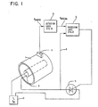
- FIG. 1 there is shown an overall view of a fuser temperature control system for a copier utlilizing the invention described herein.
- a fuser roll 1 of conventional metallic construction is heated by a heater 2.
- the heater 2 is conventionally a source such as a lamp, or a series of high temperatures wires, supplied by a power supply 3 providing an alternating voltage V AC .
- the power supply is selectively connectable to the heater 2 by operation of a switching triac 7.
- the temperature of the fuser roll is sensed by a sensor 4 which supplies analog signals to the detection logic 5.
- Detection logic 5 serves to eliminate noise and convert the analog voltage to digital data representations utilizable by processing logic 6, which gates the triac 7.
- Control signals received by the processing logic 6 are digital data representations from the detection logic 5, representing fuser roll 1 temperature, and signals on line 8 indicating the alternating line voltage from the power supply 3.
- the purpose of the system. shown in Figure 1 is to control the temperature of the fuser roll 1, with a selective degree of control.
- the degree of control required during normal copy runs is more stringent than that required during "standby" operations when the copier is awaiting use.
- the processing logic 6 operates the traic 7 to supply to the heater 2 selected ones of the half-cycles from the power supply 3.
- the processing logic 6 selects those half-cycles necessary to maintain the fuser roll 1 at a temperature within a tolerance range depending on the current mode of operation of the copier, while minimizing the difference between the number of positive and negative half-cycles selected to: (a) provide as small a DC component to the heater 2 as possible and (b) to keep the average current over short periods close to the average current over longer periods.
- the processing logic may operate the triac 7 to supply between 0 percent and 100 percent of the maximum power available from the power supply 3 to the heater 2, the supply being incremented in steps ranging from a few percent to greater than 50 percent. During copying operations, however, the supply is incremented in steps never exceeding a few percent.
- the amount of power utilized by the heater 2 has been empirically determined for a typical gas-filled lamp. For such a lamp, the power radiated out of the lamp is approximately shown by the following relationship based on Moon's equations: where:
- the lamp will be operated to radiate 58.58 percent of its full power.
- the processing logic 6 is adjusted in accordance with temperature of the fuser roll 1 as sensed by the sensor 4, the number of half-cycles during which the lamp is operated can be changed to maintain the fuser roll 1 temperature within a desired range. For example, if detection logic 5 supplies digital signals to the processing logic 6 indicating that the temperature of the fuser roll 1 has dropped, the processing logic 6 can switch the triac 7 an increased number of times to cause the lamp to be turned on for a larger number of half-cycles.
- the processing logic 6 can cause the triac 7 to turn the lamp 2 on, for example 24 out of 32 half-cycles, causing the lamp to supply 80.09 percent of its full power. If this increased radiation from the lamp 2 causes the fuser roll temperature to rise, the sensor 4 will signal the detection logic 5 of the change and the processing logic 6 will cause the number of half-cycles to decrease. For example, if the temperature rises, the processing logic 6 may signal the triac 7 to pass to the lamp 2 10 out of 32 half-cycles causing the lamp to operate at 40.76 percent of its full power. The processing logic 6 may change the proportion of "on" half-cycles after any full set (M) of 32 half-cycles has been completed.
- M full set
- processing logic 6 to select the number of cycles of operation of a lamp 2 to maintain the temperature of a fuser roll 1 within a tolerance range. Still to be described in detail are the techniques of operation of the processing logic 6, the technique for minimizing imbalance between the number of positive and negative half-cycles (causing undesirable DC current components), the technique for avoiding noise generation by switching the triac 7 only at voltage zero-crossings, and the technique for selectively providing different operation for different modes of copier operation.
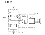
- the detection logic 5 comprises the sensor 4 configured as a bridge circuit where in a thermistor 21 is provided in one arm of a bridge also containing three resistors, R1, R2 and R3.
- the thermistor 21 changes its resistance in accordance with the temperature to which it is subjected. The degree of imbalance of the bridge determines an output temperature signal. It will be understood that other temperature sensing techniques can be used, preferably utilizing solid state sensors.
- Detection logic 5 includes an error voltage generator comprising a resistor R4 and an operational amplifier 22, and an analog-to-digital converter 23 which supplies binary digital data in parallel on lines DO-D3 to processing logic 6 in Figure 3.
- the digital data representation DO-D3 from detection logic 5 in Figure 2 is latched in a gated buffer 31 and made available during the period of latching to a comparator 32. It is not essential that DO-D3, available from the latch to the comparator 32, digitally corresponds to the actual temperature sensed on the fuser roll on any particular temperature scale. For example, for simplicity, it may be useful to view DO-D3 as representing the number 15 when the fuser roll 1 is for example at 100 degrees Celsius, and the number 0 when the fuser roll is at 85°C.
- the comparator 32 also receives bits on four additional lines BO-B3 representing another digital number according to any convenient code.
- the comparator 32 detects a predetermined mathematical relationship between DO-D3 and BO-B3 e.g., when the number represented by BO-B3 is greater than or equal to that represented by DO-D3, a signal occurs on its output line connected to operational amplifier 41.
- Other mathematical relationships are however possible in other embodiments e.g., the reverse relationship to the one given, or an equality relationship only. Broadly the information supplied to the comparator should be selected with the ultimate objective in mind.
- the signal at the output of the comparator 32 passes through the operational amplifier 41 and an operational amplifier 42 to a pulse transformer 43 before gating the triac 7 in Figure 1.
- the operational amplifier 41 may be selectively supplied with an override signal for test purposes.
- the operational amplifier 42 is modulated by a high frequency signal to permit the use of a relatively small pulse transformer 43.
- the triac 7 is operated for one cycle of the current from the source 3 for each signal from the comparator 32, in accordance with the normal mode of operation of triacs.
- the number represented by BO-B3 is determined by the number of the current half-cycle in the set of half-cycles M.
- each half-cycle in the sequence of 32 half-cycles is numbered in sequence from 1 through 32.
- the current number is compared to the temperature value DO-D3 currently in latch 31.
- the address entered in register 38 provides an argument for a table in one of the read-only stores 35 and 36, which argument causes BO-B3 to be supplied to the data-out register 34.
- the same BO-B3 will always be found for a particular argument, and two or more different arguments may give the same BO-B3.
- the necessary accessing operations required to perform the table look-up are performed by a central processing unit 37.
- the address supplied to the address register 38 is provided by a counter 39 which is stepped by a zero-crossing detector 40 connected by line 8 to the power supply 3 in Figure 1.
- the zero-crossing detector 40 supplies a signal whenever the power supply voltage from the power supply circuit 3 goes through 0. This not only identifies the beginning of each half-cycle, but also enables all switching operations to occur when the power supply voltage is at or near 0; this reduces noise generation and reduces the necessary size of switching components.
- the pulses from the zero-crossing detector 40 step the counter 39 to indicate to the address register 38 the sequential number of the half-cycle. For example the first one of 32 half-cycles will cause the number 1 to be entered in the register 38, the second will cause the number 2 to be entered therein, etc.
- a different address is entered into the address register 38, which causes the same or a different number, depending on the table in read-only storage 35 or 36, to be placed in the data-out register 34.
- the triac 7 is gated to pass one half-cycle of current to the heater 2.
- the counter 39 has an output connected to the buffer latch 31 which signals the occurrence of the end of a cycle of operation; that is, when M half-cycles of the power supply 3 have occurred, the buffer latch 31 is gated to enter a new digital data representation DO-D3 of the temperature sensed by the sensor 4.
- the processing logic 6 has an input for indicating to the central processing unit 37 whether the copier is in standby or run mode.
- One use of this information is to control the selection of the particular read-only store 35 or 36 which is used effectively for converting the data in the address register 38 to the data in the data-out register 34.
- read-only storage 35 may be used for standby operations, and a different table in read-only storage 36 may be used when the copier is in a run mode.
- the half-cycles are shown sequentially numbered across the top from 0 through 31, with their alternating polarities indicated by the signs "+" and "-".
- the half-cycle numbers 0-31 are the numbers supplied by the counter 39 to the address register 38.
- the particular mode of copier operation shown by Table II is a copy run operation where accurate temperature control is essential.
- the read-only store 36 in the processor 33 is assumed to be selected for this operation.
- the read-only store 36 stores a table containing as arguments the half-cycle numbers shown in Table 11, and the corresponding B numbers (each represented by a particular B0B3 in Figure 3) shown below them in Table II.
- the B numbers are shown in Table II for positive half-cycles in one row, and for negative half-cycles in a second row.
- the number 14 will be supplied by the read-only store 36 to the data out register 34.
- the data out register 34 will receive the number 15.
- the comparator 32 will give an output signal wheneverthe B number is greater than or equal to the digital number (DO-D3 in Figure 3) representing the temperature supplied by the buffer latch 31.
- the digital number representing the temperature supplied to the comparator 32 is chosen to be in the range of 0-15 as shown in the column to the left of Table II.
- a temperature value of 0 indicates that the temperature of the fuser roll 1 is considerably below the desired temperature, whereas a temperature value of 15 indicates thatthe difference from the desired temperature is either nonexistent or very small.
- the comparator 32 sends a signal to the triac 7 causing it to conduct the one-half cycle as shown by a 1 digit in the Table II.
- the B number 14 is greater than or equal to the temperature value in fifteen of the possible sixteen values shown. The only time that this is not true is if the temperature value is 15; that is, the fuser temperature is at or above its desired value 15.
- the B number is 8, which will cause the triac 7 to be gated in nine of the sixteen possible temperature cases.
- the number of half-cycles during which the triac 7 is operated is predetermined. That is, if the temperature value is 15, the first line of "1's" shows that seventeen out of thirty-two of the half-cycles will be selected.
- the two right hand columns in Table 11 indicate the DC component of the current supplied to the heater 2, and the percentage of total power supplied to the heater 2.
- the number of negative half-cycles exceeds the number of positive half-cycles by one, and the total average power supplied is 61.39 percent of the full power of the lamp.
- the row numbered 0 indicates that all thirty-two of the available thirty-two half-cycles will be supplied to the lamp, giving 100 percent of the lamp's full power and a DC component of 0. It will be seen that the B numbers are such that the number of half-cycles supplied to the lamp per set of 32 half-cycles i.e., per cycle of operation of the apparatus, varies inversely with the magnitude of the temperature value. In Table II, the difference between the number of positive and negative half-cycles is never more than one. Also the half-cycles supplied to the lamp are spread throughout the apparatus cycle.
- Table III is organised in the same manner as Table I1.
- the difference between standby operation of a copier and a copy run operation mode of a copier is that, in the former, it is not essential that the temperature of the fuser roll 1 be maintained as accurately. Therefore, when the temperature value D is 15, it is permissible to shut off the fuser; this is shown in the first line of Table III. Thus when the temperature value is 15, no half-cycles of the available thirty-two are selected and the power supplied to the heater is 0 percent. When the temperature of the fuser 1 drops to give a temperature value, for example to a value of 14 as shown in the second row, there will be a change from providing zero half-cycles to providing eighteen half-cycles.
- the power supplied to the heater 2 may vary between 0 percent and 64.15 percent of the full power for a small temperature change. This should be contrasted with the copy run mode of operation shown in Table II where a similar temperature variation will give a much smaller percentage change, i.e., from 61.39 percent to 64.15 percent.
- Figures 4A and 4B show a block diagram of a programmable machine controller described in detail in our U.S. Patent No. 4,086,658.
- the processor 33 ( Figure 3) includes a microprocessor 170 which is detailed in Figure 4B.
- the microprocessor 170 is attached to a bus to which is attached read-only store 171, a working memory 172 and input and output registers 173 and 174 useful for communications with external devices such as a temperature sensor 4.
- a clock 176 provides timing signals.
- the microprocessor 170 of Figure 4B comprises the circuits necessary to perform instructions in accordance with a program of instructions supplied in binary machine code derived from commands in assembly language as detailed in the referenced patent.
- the instructions which determine the movement of data among the registers shown, define operations in the particular processor described in the referenced patent. It is within the scope of the invention to utilise discrete logic design techniques or to substitute another processor for the one shown and to utilise an appropriate instruction language therefor, such as BASIC.
- the triac 7 is turned on for one half-cycle. If the value is less than the present fuser temperature value, the triac 7 is turned off for a half-cycle. The routine then fetches another B number and, for every 64 fetches, it causes another temperature value sampling.
Description
- The invention relates to an electrophotographic copier having an electrically heated fuser and a control apparatus for regulating the temperature of the fuser.
- In an electrophotographic apparatus, for example a xerographic copier, a pattern of toner is placed on paper in accordance with an image on an original document. The toner is fixed on the paper to form a permanent copy of the original image by applying a combination of heat and pressure to the toner and paper. For example, in a typical copier, the paper carrying loosely adhering toner is passed between a heated fuser roll and a backup roll to essentially melt the toner into the paper.
- The quality of the result depends upon the temperature to which the paper is brought during the fusing operation. At the extremes, too high a temperature will undesirably remove toner from the paper, while too low a temperature will fail to properly bond the toner to the paper. In practical systems, a major problem is non-uniformity of heat application over the duration of a "copy run" i.e., during the copying of one or more originals in a single continuous operator-initiated job. Successive sheets of paper may reach different temperatures, not all within the acceptable range, and different sizes of paper may reach different temperatures at different times. Further, within a copy run, not all parts of the same sheet of paper will be within the acceptable range of temperature during the entire fusing operation, resulting in a wide spectrum of quality problems involving the paper and toner. These problems are believed to be due to many factors, such as: differing thermal load presented by different qualities, sizes and weights of paper; materials and environmental factors affecting the thermal transfer between the fuser surface and the paper; and the degree of temperature control achieved at the surface where the paper contacts the fuser.
- A physically massive fuser roll will eventually reach a stable surface temperature which is substantially independent of external factors such as the size and quantity of paper placed in contact with it or the rate at which the paper is fed past the roller. However, copier size, energy availability and time-to-first-copy restrictions dictate that a fuser roll be as physically small as possible. Commercial couplers acceptable in an office environment ideally must be physically small, cannot generate excessive quantities of heat and must be connectable to a conventional electrical power outlet. The fuser heater is often a major source of heat and user of electrical energy, and the size of the fuser is a significant factor in the size of the copier. A small fuser is desirable at least because it generates less heat, uses less power, takes up less space. However, the smaller the fuser roll mass relative to the mass of the copy paper, the greater will be the thermal load effect of the paper on the roll. That is, each sheet will have a greater cooling effect on a small roll than on a large roll. The technique used to maintain the fuser roll at a constant temperature, regardless of external thermal factors, thus becomes extremely important for a fuser roll of smaller mass. This is especially the case where a large thermal load can arise, e.g., as in a fast copier, in which many sheets of paper are rapidly fed through the fuser.
- The prior art discloses a number of approaches to the problem of accurately controlling fuser temperature. The simplest prior art approach provides an on-off thermostat in series with the fuser heater. While this provides control of fuser temperature, on-off cycling does not give the accuracy required by compact and fast copiers, even where the thermostat is extremely accurate. The primary disadvantage of on-off cycling is that the peak power requirements are significantly greater than the average power used for heating. Thus, a copier with an on-off thermostat may need to be connected to an undesirably large current source. For example, a typical commercial copier with an on-off thermostat may require a dedicated power circuit capable of supplying as much as 3-5 kilowatts. This large power requirement is determined in part by "worst case" fuser conditions, such as the age of the heating element, original manufacturing tolerances and line voltage variations.
- Another prior art approach is to supply only a portion of each power cycle of an alternating supply to heat the fuser. The portions are selected as a function of the fuser temperature sensed by a thermostat. Shortcomings of this approach are that, since it requires electronic switching of substantial load currents, physically large electrical parts are required, energy may be wasted and undesirable electromagnetic radiation occurs.
- Some specific examples of prior art are briefly commented on. In U.S.-A-3,961,236, accuracy is increased by monitoring fuser heater voltage and current and then adjusting input power to maintain power consumption constant. Adjustment is obtained by controlling the number of complete alternating current half-cycles supplied by a power source to the fuser. Since the load current is supplied in complete half-cycles, switching of the load current may be accomplished at zero-crossings to greatly reduce component size, electromagnetic noise and, in some cases, energy dissipation.
- A lamp dimmer disclosed in U.S.-A-3,691,404 selects groups of alternating current cycles in accordance with digital quantities chosen by manually adjusting a switch. The cycles are switched at zero-crossings. U.S.-A-3,259,825 shows a servo drive wherein varying numbers of positive half-cycles are selected at zero-crossings as a function of a control voltage. U.S. Patent No. 3,456,095 selects the frequency at which positive half-cycles of power are supplied to a heater as a function of signals from a heat sensor.
- Typical problems of such prior art approaches are that high instantaneous or average currents are switched, special electrical supply sources are required, electromagnetic noise is generated, fuser temperature is not sensed, undesirable direct current components are present (when the difference between the numbers of positive and negative half-cycles is not zero), large physical size is necessary, finely graduated adjustments are not possible, manual intervention is required, etc.
- U.S.-A-3,878,358 relates to regulating fuser temperature in a copier, and the introductory part of
claim 1 is based on it. The technique can be regarded as involving the comparison of the current fuser resistance with a predetermined sequence of resistances, selected in turn in a cycle. This US Patent does not disclose spreading the generated pulses throughout the cycle, and using one sensed fuser temperature for the whole cycle, these techniques providing an important improvement in the fuser temperature regulation. - Document EP-A-6553 discloses regulating fuser temperature in a copier. It has an earlier priority date than the present application, but was first published after the priority date of the present application, and is therefore only to be considered in relation to novelty and not inventive step of the present invention.
- The regulation temperature is based on comparing the fuser temperature with a single predetermined temperature value (T2), see elements 215 and 219 of Fig. 9B), rather than with a predetermined sequence of signals as in the present invention.
- EP-A-11863 discloses regulating fuser temperature in a copier. It also has an earlier priority date than the present application, but was first published after the priority date of the present application, and is therefore only to be considered in relation to novelty and not inventive step of the present invention. The regulation technique is based on determining the analogue temperature of the fuser, converting the analogue temperature to a five bit code, and gating power pulses to the fuser depending on the current five bit code. There is no comparison of the fuser temperature with a predetermined sequence of signals as in the present invention.
- U.S.-A-3,491,283 discloses regulating the application of pulses to a load by a technique which has some similarities to EP-A-11863. There is no comparison of a digital control value with a predetermined sequence of signals, but the technique provides spacing of generated pulses per cycle.
- In the drawings:-
- Figure 1 is an overall view of a fuser temperature control system according to the invention;
- Figure 2 is a circuit diagram of part of the system of Figure 1;
- Figure 3 is a block circuit diagram of another part of the system of Figure 1;
- Figures 4A and 4B are detailed block circuit diagrams relevant to Figure 3; and
- Figure 5 is a very general flow diagram of operations performed in the system.
- Referring to Figure 1, there is shown an overall view of a fuser temperature control system for a copier utlilizing the invention described herein. A
fuser roll 1 of conventional metallic construction is heated by aheater 2. Theheater 2 is conventionally a source such as a lamp, or a series of high temperatures wires, supplied by apower supply 3 providing an alternating voltage VAC. The power supply is selectively connectable to theheater 2 by operation of a switchingtriac 7. The temperature of the fuser roll is sensed by asensor 4 which supplies analog signals to the detection logic 5. Detection logic 5 serves to eliminate noise and convert the analog voltage to digital data representations utilizable byprocessing logic 6, which gates thetriac 7. Control signals received by theprocessing logic 6 are digital data representations from the detection logic 5, representingfuser roll 1 temperature, and signals on line 8 indicating the alternating line voltage from thepower supply 3. - The purpose of the system. shown in Figure 1 is to control the temperature of the
fuser roll 1, with a selective degree of control. For example, the degree of control required during normal copy runs is more stringent than that required during "standby" operations when the copier is awaiting use. - Broadly, the
processing logic 6 operates thetraic 7 to supply to theheater 2 selected ones of the half-cycles from thepower supply 3. Theprocessing logic 6 selects those half-cycles necessary to maintain thefuser roll 1 at a temperature within a tolerance range depending on the current mode of operation of the copier, while minimizing the difference between the number of positive and negative half-cycles selected to: (a) provide as small a DC component to theheater 2 as possible and (b) to keep the average current over short periods close to the average current over longer periods. For example, during standby operation, the processing logic may operate thetriac 7 to supply between 0 percent and 100 percent of the maximum power available from thepower supply 3 to theheater 2, the supply being incremented in steps ranging from a few percent to greater than 50 percent. During copying operations, however, the supply is incremented in steps never exceeding a few percent. - The amount of power utilized by the
heater 2 has been empirically determined for a typical gas-filled lamp. For such a lamp, the power radiated out of the lamp is approximately shown by the following relationship based on Moon's equations:
- P Radiant power out
- Po Rated maximum power of lamp at Vo
- V" Voltage (RMS) available from
power supply 3 - VTRIAC Voltage across
triac 7 - N Number of power supply half-cycles selected
- M Number of power supply half-cycles in the set from which N is selected
- Vo Rated voltage of the lamp
- For example, in the above table, if 16 of the 32 available half-cycles in a set are supplied to the
lamp 2, the lamp will be operated to radiate 58.58 percent of its full power. If theprocessing logic 6 is adjusted in accordance with temperature of thefuser roll 1 as sensed by thesensor 4, the number of half-cycles during which the lamp is operated can be changed to maintain thefuser roll 1 temperature within a desired range. For example, if detection logic 5 supplies digital signals to theprocessing logic 6 indicating that the temperature of thefuser roll 1 has dropped, theprocessing logic 6 can switch thetriac 7 an increased number of times to cause the lamp to be turned on for a larger number of half-cycles. Thus, if the lamp is being turned on for 16 out of 32 half-cycles and the temperature has decreased, theprocessing logic 6 can cause thetriac 7 to turn thelamp 2 on, for example 24 out of 32 half-cycles, causing the lamp to supply 80.09 percent of its full power. If this increased radiation from thelamp 2 causes the fuser roll temperature to rise, thesensor 4 will signal the detection logic 5 of the change and theprocessing logic 6 will cause the number of half-cycles to decrease. For example, if the temperature rises, theprocessing logic 6 may signal thetriac 7 to pass to thelamp 2 10 out of 32 half-cycles causing the lamp to operate at 40.76 percent of its full power. Theprocessing logic 6 may change the proportion of "on" half-cycles after any full set (M) of 32 half-cycles has been completed. - The foregoing discussion briefly illustrates the utilization of
processing logic 6 to select the number of cycles of operation of alamp 2 to maintain the temperature of afuser roll 1 within a tolerance range. Still to be described in detail are the techniques of operation of theprocessing logic 6, the technique for minimizing imbalance between the number of positive and negative half-cycles (causing undesirable DC current components), the technique for avoiding noise generation by switching thetriac 7 only at voltage zero-crossings, and the technique for selectively providing different operation for different modes of copier operation. - Referring now to Figures 2 and 3, the detection logic 5 and
processing logic 6 will now be described. In Figure 2, the detection logic 5 comprises thesensor 4 configured as a bridge circuit where in athermistor 21 is provided in one arm of a bridge also containing three resistors, R1, R2 and R3. Thethermistor 21 changes its resistance in accordance with the temperature to which it is subjected. The degree of imbalance of the bridge determines an output temperature signal. It will be understood that other temperature sensing techniques can be used, preferably utilizing solid state sensors. Detection logic 5 includes an error voltage generator comprising a resistor R4 and anoperational amplifier 22, and an analog-to-digital converter 23 which supplies binary digital data in parallel on lines DO-D3 toprocessing logic 6 in Figure 3. The example shown herein assumes that the voltage representing the temperature sensed bythermistor 21 is converted into a numerical value represented by binary encoded data on four lines DO-D3 simultaneously. It is not, however, essential to the invention that this particular convention be used because any suitable form of digital representation will suffice. - In Figure 3, the digital data representation DO-D3 from detection logic 5 in Figure 2 is latched in a
gated buffer 31 and made available during the period of latching to acomparator 32. It is not essential that DO-D3, available from the latch to thecomparator 32, digitally corresponds to the actual temperature sensed on the fuser roll on any particular temperature scale. For example, for simplicity, it may be useful to view DO-D3 as representing the number 15 when thefuser roll 1 is for example at 100 degrees Celsius, and the number 0 when the fuser roll is at 85°C. Thecomparator 32 also receives bits on four additional lines BO-B3 representing another digital number according to any convenient code. When thecomparator 32 detects a predetermined mathematical relationship between DO-D3 and BO-B3 e.g., when the number represented by BO-B3 is greater than or equal to that represented by DO-D3, a signal occurs on its output line connected tooperational amplifier 41. Other mathematical relationships are however possible in other embodiments e.g., the reverse relationship to the one given, or an equality relationship only. Broadly the information supplied to the comparator should be selected with the ultimate objective in mind. The signal at the output of thecomparator 32 passes through theoperational amplifier 41 and anoperational amplifier 42 to apulse transformer 43 before gating thetriac 7 in Figure 1. Theoperational amplifier 41 may be selectively supplied with an override signal for test purposes. Theoperational amplifier 42 is modulated by a high frequency signal to permit the use of a relativelysmall pulse transformer 43. Thetriac 7 is operated for one cycle of the current from thesource 3 for each signal from thecomparator 32, in accordance with the normal mode of operation of triacs. - The number represented by BO-B3 is determined by the number of the current half-cycle in the set of half-cycles M.
- For example, where M equals 32, each half-cycle in the sequence of 32 half-cycles is numbered in sequence from 1 through 32. The current number is compared to the temperature value DO-D3 currently in
latch 31. For BO-B3 the address entered inregister 38 provides an argument for a table in one of the read-only stores 35 and 36, which argument causes BO-B3 to be supplied to the data-out register 34. For each table, the same BO-B3 will always be found for a particular argument, and two or more different arguments may give the same BO-B3. The necessary accessing operations required to perform the table look-up are performed by a central processing unit 37. The address supplied to theaddress register 38 is provided by acounter 39 which is stepped by a zero-crossingdetector 40 connected by line 8 to thepower supply 3 in Figure 1. The zero-crossingdetector 40 supplies a signal whenever the power supply voltage from thepower supply circuit 3 goes through 0. This not only identifies the beginning of each half-cycle, but also enables all switching operations to occur when the power supply voltage is at or near 0; this reduces noise generation and reduces the necessary size of switching components. The pulses from the zero-crossingdetector 40 step thecounter 39 to indicate to theaddress register 38 the sequential number of the half-cycle. For example the first one of 32 half-cycles will cause thenumber 1 to be entered in theregister 38, the second will cause thenumber 2 to be entered therein, etc. - For each zero-crossing of the power supply 3 a different address is entered into the
address register 38, which causes the same or a different number, depending on the table in read-only storage 35 or 36, to be placed in the data-out register 34. Every time a predetermined mathematical relationship is satisfied between the number in the data-out register 34 and the number specified to thecomparator 32 by thebuffer latch 31, thetriac 7 is gated to pass one half-cycle of current to theheater 2. Thecounter 39 has an output connected to thebuffer latch 31 which signals the occurrence of the end of a cycle of operation; that is, when M half-cycles of thepower supply 3 have occurred, thebuffer latch 31 is gated to enter a new digital data representation DO-D3 of the temperature sensed by thesensor 4. Theprocessing logic 6 has an input for indicating to the central processing unit 37 whether the copier is in standby or run mode. One use of this information is to control the selection of the particular read-only store 35 or 36 which is used effectively for converting the data in theaddress register 38 to the data in the data-out register 34. For example, read-only storage 35 may be used for standby operations, and a different table in read-only storage 36 may be used when the copier is in a run mode. - For example, reference is made to Table II below where the information necessary to convert data representing half-cycle sequence numbers to data representing power supply half-cycle selection signals is shown for one possible mode of copier operation.

- In Table II, the half-cycles are shown sequentially numbered across the top from 0 through 31, with their alternating polarities indicated by the signs "+" and "-". The half-cycle numbers 0-31 are the numbers supplied by the
counter 39 to theaddress register 38. The particular mode of copier operation shown by Table II is a copy run operation where accurate temperature control is essential. The read-only store 36 in the processor 33 is assumed to be selected for this operation. The read-only store 36 stores a table containing as arguments the half-cycle numbers shown in Table 11, and the corresponding B numbers (each represented by a particular B0B3 in Figure 3) shown below them in Table II. For clarity, the B numbers are shown in Table II for positive half-cycles in one row, and for negative half-cycles in a second row. For example, when thecounter 39 is set to 0 and supplies a number 0 to theaddress register 38, the number 14 will be supplied by the read-only store 36 to the data outregister 34. When the counter is stepped by the zero-crossingdetector 40 to thenext number 1, the data outregister 34 will receive the number 15. Thecomparator 32 will give an output signal wheneverthe B number is greater than or equal to the digital number (DO-D3 in Figure 3) representing the temperature supplied by thebuffer latch 31. The digital number representing the temperature supplied to thecomparator 32 is chosen to be in the range of 0-15 as shown in the column to the left of Table II. A temperature value of 0 indicates that the temperature of thefuser roll 1 is considerably below the desired temperature, whereas a temperature value of 15 indicates thatthe difference from the desired temperature is either nonexistent or very small. Whenever the temperature value at thebuffer latch 31 is less than or equals the B number at the data outregister 34, thecomparator 32 sends a signal to thetriac 7 causing it to conduct the one-half cycle as shown by a 1 digit in the Table II. In the first column, the B number 14 is greater than or equal to the temperature value in fifteen of the possible sixteen values shown. The only time that this is not true is if the temperature value is 15; that is, the fuser temperature is at or above its desired value 15. Similarly, taking for example the 32nd half-cycle, which isnumber 31, the B number is 8, which will cause thetriac 7 to be gated in nine of the sixteen possible temperature cases. - Still referring to Table II, it can be seen that for a given temperature value, the number of half-cycles during which the
triac 7 is operated is predetermined. That is, if the temperature value is 15, the first line of "1's" shows that seventeen out of thirty-two of the half-cycles will be selected. The two right hand columns in Table 11 indicate the DC component of the current supplied to theheater 2, and the percentage of total power supplied to theheater 2. For a temperature value of 15, the number of negative half-cycles exceeds the number of positive half-cycles by one, and the total average power supplied is 61.39 percent of the full power of the lamp. If the temperature value is the lowest listed, the row numbered 0 indicates that all thirty-two of the available thirty-two half-cycles will be supplied to the lamp, giving 100 percent of the lamp's full power and a DC component of 0. It will be seen that the B numbers are such that the number of half-cycles supplied to the lamp per set of 32 half-cycles i.e., per cycle of operation of the apparatus, varies inversely with the magnitude of the temperature value. In Table II, the difference between the number of positive and negative half-cycles is never more than one. Also the half-cycles supplied to the lamp are spread throughout the apparatus cycle. - Referring now to Table III, the data which may be stored in read-only storage 35 for a standby mode of operation is given.

- Table III is organised in the same manner as Table I1. The difference between standby operation of a copier and a copy run operation mode of a copier is that, in the former, it is not essential that the temperature of the
fuser roll 1 be maintained as accurately. Therefore, when the temperature value D is 15, it is permissible to shut off the fuser; this is shown in the first line of Table III. Thus when the temperature value is 15, no half-cycles of the available thirty-two are selected and the power supplied to the heater is 0 percent. When the temperature of thefuser 1 drops to give a temperature value, for example to a value of 14 as shown in the second row, there will be a change from providing zero half-cycles to providing eighteen half-cycles. Thus, the power supplied to theheater 2 may vary between 0 percent and 64.15 percent of the full power for a small temperature change. This should be contrasted with the copy run mode of operation shown in Table II where a similar temperature variation will give a much smaller percentage change, i.e., from 61.39 percent to 64.15 percent. - Referring now to Figures 4A, 4B and 5, Figures 4A and 4B show a block diagram of a programmable machine controller described in detail in our U.S. Patent No. 4,086,658. The processor 33 (Figure 3) includes a
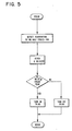
microprocessor 170 which is detailed in Figure 4B. Themicroprocessor 170 is attached to a bus to which is attached read-only store 171, a workingmemory 172 and input andoutput registers temperature sensor 4. Aclock 176 provides timing signals. Themicroprocessor 170 of Figure 4B comprises the circuits necessary to perform instructions in accordance with a program of instructions supplied in binary machine code derived from commands in assembly language as detailed in the referenced patent. The instructions, which determine the movement of data among the registers shown, define operations in the particular processor described in the referenced patent. It is within the scope of the invention to utilise discrete logic design techniques or to substitute another processor for the one shown and to utilise an appropriate instruction language therefor, such as BASIC. - For purposes of completeness, there follows at the end of this description, a listing of source code in assembly language for use with the processor shown in Figures 4A and 4B. The listing organisation is very generally outlined in the flow diagram of Figure 5. The fuser temperature is detected by the
sensor 4 by sampling and analog-to-digital conversion. In Figure 5 there is a minor change in that the fuser temperature is sampled after every 64 half-cycles. As previously, the number of the present zero-crossing, that is the half-cycle number indicated in thecounter 39, is used as an argument to fetch a value from a table (for example, based on Table I or II) in one of the read-only stores 35 and 36. If the B number obtained from the table is greater than or equal to the present fuser temperature value, thetriac 7 is turned on for one half-cycle. If the value is less than the present fuser temperature value, thetriac 7 is turned off for a half-cycle. The routine then fetches another B number and, for every 64 fetches, it causes another temperature value sampling.


Assuming that a (theoretically 100 percent efficient) lamp having a rating of 700 watts (Po) at 127 volts (Vo) RMS is used and that a sequence of 32 half-cycles (16 cycles) of the power supply is taken as a set (M) the following table shows the percentage of power radiated by the lamp as a function of the number of half-cycles selected.


Claims (3)
Applications Claiming Priority (2)
| Application Number | Priority Date | Filing Date | Title |
|---|---|---|---|
| US10250879A | 1979-12-11 | 1979-12-11 | |
| US102508 | 1979-12-11 |
Publications (3)
| Publication Number | Publication Date |
|---|---|
| EP0030372A2 EP0030372A2 (en) | 1981-06-17 |
| EP0030372A3 EP0030372A3 (en) | 1982-03-24 |
| EP0030372B1 true EP0030372B1 (en) | 1985-10-16 |
Family
ID=22290231
Family Applications (1)
| Application Number | Title | Priority Date | Filing Date |
|---|---|---|---|
| EP80107615A Expired EP0030372B1 (en) | 1979-12-11 | 1980-12-04 | Electrophotographic copier |
Country Status (2)
| Country | Link |
|---|---|
| EP (1) | EP0030372B1 (en) |
| DE (1) | DE3071191D1 (en) |
Families Citing this family (3)
| Publication number | Priority date | Publication date | Assignee | Title |
|---|---|---|---|---|
| JPS58136072A (en) * | 1982-02-08 | 1983-08-12 | Hitachi Ltd | Fixing device of copying machine |
| DE69024140T2 (en) * | 1989-09-01 | 1996-06-13 | Canon Kk | Imaging device |
| GB2283583B (en) * | 1993-10-15 | 1998-06-24 | Seiko Epson Corp | Temperature control in a fixing device for an image forming apparatus |
Citations (2)
| Publication number | Priority date | Publication date | Assignee | Title |
|---|---|---|---|---|
| EP0006553A1 (en) * | 1978-07-03 | 1980-01-09 | International Business Machines Corporation | Method and apparatus for operating a heat source in a reproduction machine |
| EP0011863A1 (en) * | 1978-12-04 | 1980-06-11 | GENICOM Corporation | Current controller for an electrical load |
Family Cites Families (4)
| Publication number | Priority date | Publication date | Assignee | Title |
|---|---|---|---|---|
| GB1135269A (en) * | 1966-07-20 | 1968-12-04 | Rosemount Eng Co Ltd | Improvements in or relating to systems for controlling electrical power |
| US3878358A (en) * | 1972-11-16 | 1975-04-15 | Xerox Corp | Digital power control |
| US3961236A (en) * | 1975-02-07 | 1976-06-01 | Xerox Corporation | Constant power regulator for xerographic fusing system |
| JPS5339136A (en) * | 1976-09-22 | 1978-04-10 | Ricoh Co Ltd | Fixing temperature controlling method |
-
1980
- 1980-12-04 EP EP80107615A patent/EP0030372B1/en not_active Expired
- 1980-12-04 DE DE8080107615T patent/DE3071191D1/en not_active Expired
Patent Citations (2)
| Publication number | Priority date | Publication date | Assignee | Title |
|---|---|---|---|---|
| EP0006553A1 (en) * | 1978-07-03 | 1980-01-09 | International Business Machines Corporation | Method and apparatus for operating a heat source in a reproduction machine |
| EP0011863A1 (en) * | 1978-12-04 | 1980-06-11 | GENICOM Corporation | Current controller for an electrical load |
Also Published As
| Publication number | Publication date |
|---|---|
| DE3071191D1 (en) | 1985-11-21 |
| EP0030372A2 (en) | 1981-06-17 |
| EP0030372A3 (en) | 1982-03-24 |
Similar Documents
| Publication | Publication Date | Title |
|---|---|---|
| US4374321A (en) | Automatic temperature controller for an electrophotographic apparatus fuser and method therefor | |
| US3878358A (en) | Digital power control | |
| US4435677A (en) | Rms voltage controller | |
| EP0073324B1 (en) | Copier fuser control apparatus and method | |
| US3961236A (en) | Constant power regulator for xerographic fusing system | |
| US4496829A (en) | Bang-bang dual-mode integral controller with proportional control output useful for temperature control | |
| GB2067319A (en) | Controlling fuser in electrostatic reproduction apparatus | |
| EP0836123B1 (en) | Image heating apparatus | |
| US6157010A (en) | Heater control device | |
| EP0030372B1 (en) | Electrophotographic copier | |
| US4723068A (en) | Electric power control device in an automatic temperature adjusting apparatus | |
| US8521051B2 (en) | Apparatus and method of controlling power supply to heating roller and phase control circuit corresponding to the apparatus and method | |
| US5946526A (en) | Method and device for controlling temperature of heating source of image forming apparatus | |
| JPS5773773A (en) | Method for warranting quality of copy of copier | |
| GB2072887A (en) | Control of electrical heating elements | |
| JPS6348349B2 (en) | ||
| GB2108730A (en) | Power control unit | |
| JP2000268939A (en) | Heater device and thermal fixing device using the same | |
| US6114669A (en) | Apparatus for controlling the power supply to a load in a reproduction apparatus, more particularly to a fixing unit | |
| US2546926A (en) | Electrical regulation system | |
| JPH056195B2 (en) | ||
| JP3599365B2 (en) | Heater temperature control method in image forming apparatus | |
| JPH01186781A (en) | Electric power control device for heater | |
| GB2222278A (en) | Control of electric heating | |
| KR0159672B1 (en) | Fixing temperature control device by using electrophotographic developing method |
Legal Events
| Date | Code | Title | Description |
|---|---|---|---|
| PUAI | Public reference made under article 153(3) epc to a published international application that has entered the european phase |
Free format text: ORIGINAL CODE: 0009012 |
|
| AK | Designated contracting states |
Kind code of ref document: A2 Designated state(s): DE FR GB |
|
| PUAL | Search report despatched |
Free format text: ORIGINAL CODE: 0009013 |
|
| AK | Designated contracting states |
Kind code of ref document: A3 Designated state(s): DE FR GB |
|
| 17P | Request for examination filed |
Effective date: 19820415 |
|
| GRAA | (expected) grant |
Free format text: ORIGINAL CODE: 0009210 |
|
| AK | Designated contracting states |
Kind code of ref document: B1 Designated state(s): DE FR GB |
|
| REF | Corresponds to: |
Ref document number: 3071191 Country of ref document: DE Date of ref document: 19851121 |
|
| ET | Fr: translation filed | ||
| PLBE | No opposition filed within time limit |
Free format text: ORIGINAL CODE: 0009261 |
|
| STAA | Information on the status of an ep patent application or granted ep patent |
Free format text: STATUS: NO OPPOSITION FILED WITHIN TIME LIMIT |
|
| 26N | No opposition filed | ||
| PGFP | Annual fee paid to national office [announced via postgrant information from national office to epo] |
Ref country code: GB Payment date: 19901119 Year of fee payment: 11 |
|
| PGFP | Annual fee paid to national office [announced via postgrant information from national office to epo] |
Ref country code: FR Payment date: 19901122 Year of fee payment: 11 |
|
| PGFP | Annual fee paid to national office [announced via postgrant information from national office to epo] |
Ref country code: DE Payment date: 19901231 Year of fee payment: 11 |
|
| PG25 | Lapsed in a contracting state [announced via postgrant information from national office to epo] |
Ref country code: GB Effective date: 19911204 |
|
| GBPC | Gb: european patent ceased through non-payment of renewal fee | ||
| PG25 | Lapsed in a contracting state [announced via postgrant information from national office to epo] |
Ref country code: FR Effective date: 19920831 |
|
| PG25 | Lapsed in a contracting state [announced via postgrant information from national office to epo] |
Ref country code: DE Effective date: 19920901 |
|
| REG | Reference to a national code |
Ref country code: FR Ref legal event code: ST |