EP0030179A1 - Retaining structure for the compressor housing of a turbo engine - Google Patents
Retaining structure for the compressor housing of a turbo engine Download PDFInfo
- Publication number
- EP0030179A1 EP0030179A1 EP80401625A EP80401625A EP0030179A1 EP 0030179 A1 EP0030179 A1 EP 0030179A1 EP 80401625 A EP80401625 A EP 80401625A EP 80401625 A EP80401625 A EP 80401625A EP 0030179 A1 EP0030179 A1 EP 0030179A1
- Authority
- EP
- European Patent Office
- Prior art keywords
- structure according
- retention structure
- skin
- retention
- blades
- Prior art date
- Legal status (The legal status is an assumption and is not a legal conclusion. Google has not performed a legal analysis and makes no representation as to the accuracy of the status listed.)
- Granted
Links
- 230000014759 maintenance of location Effects 0.000 claims abstract description 26
- 239000002184 metal Substances 0.000 claims abstract description 15
- 238000007789 sealing Methods 0.000 claims abstract description 11
- 239000002131 composite material Substances 0.000 claims abstract description 10
- 229920003002 synthetic resin Polymers 0.000 claims abstract description 6
- 239000000057 synthetic resin Substances 0.000 claims abstract description 6
- 238000011144 upstream manufacturing Methods 0.000 claims abstract description 6
- 239000012634 fragment Substances 0.000 claims abstract description 4
- 238000004804 winding Methods 0.000 claims abstract description 4
- 239000004642 Polyimide Substances 0.000 claims abstract description 3
- 229920001721 polyimide Polymers 0.000 claims abstract description 3
- 230000002787 reinforcement Effects 0.000 claims abstract 6
- 239000000835 fiber Substances 0.000 claims description 4
- 239000004744 fabric Substances 0.000 claims description 3
- 230000003014 reinforcing effect Effects 0.000 claims description 2
- 230000008719 thickening Effects 0.000 claims 2
- 239000011888 foil Substances 0.000 abstract 1
- 229920005989 resin Polymers 0.000 description 4
- 239000011347 resin Substances 0.000 description 4
- 239000000463 material Substances 0.000 description 3
- 229920000049 Carbon (fiber) Polymers 0.000 description 2
- 239000004917 carbon fiber Substances 0.000 description 2
- 230000000694 effects Effects 0.000 description 2
- 241000256815 Apocrita Species 0.000 description 1
- 241000257303 Hymenoptera Species 0.000 description 1
- 229920000271 Kevlar® Polymers 0.000 description 1
- 229910000831 Steel Inorganic materials 0.000 description 1
- 238000005299 abrasion Methods 0.000 description 1
- 230000033228 biological regulation Effects 0.000 description 1
- 230000009172 bursting Effects 0.000 description 1
- 235000021183 entrée Nutrition 0.000 description 1
- 230000003628 erosive effect Effects 0.000 description 1
- 238000000605 extraction Methods 0.000 description 1
- 238000013467 fragmentation Methods 0.000 description 1
- 238000006062 fragmentation reaction Methods 0.000 description 1
- 239000003365 glass fiber Substances 0.000 description 1
- 238000009434 installation Methods 0.000 description 1
- 239000004761 kevlar Substances 0.000 description 1
- 239000004033 plastic Substances 0.000 description 1
- 125000006850 spacer group Chemical group 0.000 description 1
- 230000003068 static effect Effects 0.000 description 1
- 239000010959 steel Substances 0.000 description 1
- 210000001519 tissue Anatomy 0.000 description 1
Images
Classifications
-
- F—MECHANICAL ENGINEERING; LIGHTING; HEATING; WEAPONS; BLASTING
- F04—POSITIVE - DISPLACEMENT MACHINES FOR LIQUIDS; PUMPS FOR LIQUIDS OR ELASTIC FLUIDS
- F04D—NON-POSITIVE-DISPLACEMENT PUMPS
- F04D29/00—Details, component parts, or accessories
- F04D29/40—Casings; Connections of working fluid
- F04D29/403—Casings; Connections of working fluid especially adapted for elastic fluid pumps
-
- F—MECHANICAL ENGINEERING; LIGHTING; HEATING; WEAPONS; BLASTING
- F01—MACHINES OR ENGINES IN GENERAL; ENGINE PLANTS IN GENERAL; STEAM ENGINES
- F01D—NON-POSITIVE DISPLACEMENT MACHINES OR ENGINES, e.g. STEAM TURBINES
- F01D21/00—Shutting-down of machines or engines, e.g. in emergency; Regulating, controlling, or safety means not otherwise provided for
- F01D21/04—Shutting-down of machines or engines, e.g. in emergency; Regulating, controlling, or safety means not otherwise provided for responsive to undesired position of rotor relative to stator or to breaking-off of a part of the rotor, e.g. indicating such position
- F01D21/045—Shutting-down of machines or engines, e.g. in emergency; Regulating, controlling, or safety means not otherwise provided for responsive to undesired position of rotor relative to stator or to breaking-off of a part of the rotor, e.g. indicating such position special arrangements in stators or in rotors dealing with breaking-off of part of rotor
-
- Y—GENERAL TAGGING OF NEW TECHNOLOGICAL DEVELOPMENTS; GENERAL TAGGING OF CROSS-SECTIONAL TECHNOLOGIES SPANNING OVER SEVERAL SECTIONS OF THE IPC; TECHNICAL SUBJECTS COVERED BY FORMER USPC CROSS-REFERENCE ART COLLECTIONS [XRACs] AND DIGESTS
- Y02—TECHNOLOGIES OR APPLICATIONS FOR MITIGATION OR ADAPTATION AGAINST CLIMATE CHANGE
- Y02T—CLIMATE CHANGE MITIGATION TECHNOLOGIES RELATED TO TRANSPORTATION
- Y02T50/00—Aeronautics or air transport
- Y02T50/60—Efficient propulsion technologies, e.g. for aircraft
Definitions
- the invention relates to a retention structure for a compressor casing of a double-flow turbomachine comprising an air intake sleeve, the compressor and its casing, the engine assembly and its casing, the retention structure surrounding the compressor. .
- the characteristics that the casing of a turbomachine must have in the area of the rotating elements are as follows: no fragment must pass through the casing which must also resist the erosion of debris entrained by the rotor; the retention structure must have sufficient inertia not to undergo significant deformations or be the seat of dangerous vibrational resonances, and it must fall within the normal dimensional limits of the nacelle.
- French patent 2,282,537 describes a turbomachine casing comprising an annular internal wall which comprises, axially alternated, parts intended to hold the stator blades and parts surrounding the ends of rotor blades.
- This wall is surrounded by an outer layer of composite material reinforced by continuous carbon fibers wrapped around the wall and embedded in resin.
- the stator blades are held in inwardly facing recesses which alternate with the portions surrounding the ends of the rotor blades and having outwardly facing recesses.
- the outside of the casing is thus formed of sections of different diameter, which makes it difficult to wind the outer retention layer.
- the outward-facing recesses are filled with a honeycomb material.
- the stator blade retaining rings made of rolled steel, are separated by annular spacers formed in a plastic material. The whole is maintained and reinforced by the winding of carbon fibers embedded in the resin.
- the broken blade or blade portion is held by the metal rings, but this is not quickly removed from the casing and the only possibility of extraction consists in its fragmentation by the other blades and its evacuation by air flow.
- French patent 1,429,834 shows an embodiment which makes it possible to avoid some of the drawbacks of the device described above.
- the compressor housing consists of an inner cylindrical shell and an outer cylindrical shell between which a honeycomb structure is interposed.
- the inner envelope is itself formed of a wire mesh between two layers of resin.
- the stator vanes form a cylindrical crown and each vane passes through the honeycomb structure in which it is held by synthetic resin.
- the honeycomb structure has the function of ensuring the connection between the outer and in ⁇ térieur envelopes and ensuring the mounting of the blades, while the inner envelope opposes, by its particular constitution, abrasion by debris and its fracturing at case a dawn would come off.
- the embodiment described above is more particularly suited to a compressor for a small power reactor and of small diameter.
- the metal grid resin structure cannot withstand without significant damage the impact of a blade or debris at very high tangential speed.
- the invention aims to obtain a retention structure having a minimum mass, sufficient rigidity to ensure the connection between the air intake sleeve and the rest of the crankcase, and maximum retention power for high tangential speed debris.
- the structure according to the invention combines a layer of fibrous composite material which provides a retentive function tion and a sandwich structure which provides rigidity for good static and dynamic behavior.
- the retention structure 1, shown in FIG. 1, is fixed at its ends by means of the flanges 2 and 3 to the air bag and to the motor casing (not shown).
- This structure extends forwards and backwards over the area L swept by the blades of the rotor 4. Facing the blades of the rotor, a sealing ring 11 is fixed to the structure.
- This ring consists of a support 12 coated with a wear layer 13 and it can be removable, the support 12 being in one piece.
- the retention structure comprises, according to this embodiment, an outer layer 5 and an inner layer 6.
- the inner layer consists of a sandwich structure, formed of an inner skin 7, metallic, bonded to a honeycomb structure. bees 8, covered on the outside by a skin 9 made of synthetic resin possibly reinforced with a fabric of glass fibers or the like.
- the honeycomb structure is reinforced by the outer layer 5 of fibrous composite material, consisting for example of layers of fibers according to the commercial designation Kevlar or of a winding of polyimide fibers immobilized in a synthetic resin.
- the metal skin 7 is reinforced at 14 in the plane of the blading 4 so as to be able to withstand the cutting effect.
- This reinforced part also makes it possible to maintain the internal sheets 10 defining the aerodynamic profile of the duct.
- the honeycomb structure 8 can be replaced in equivalence by a fiber structure playing the same role.
- Figure 2 shows a second embodiment of the structure.
- This embodiment differs from the previous one by an inner skin 71 made of composite material and a reinforced part, carried by an outer skin 90 and constituted by a metal rib 15, one end of which is extended by a wing and is opposite the blade.
- the metallic outer skin 90 carries the flanges 2 and 3 at its ends.
- the structure function 6 is provided by a sandwich material constituted by two skins 91 and 72 of composite material bonded to a core of the honeycomb type 8.
- Metal flanges 21 and 31 bonded to each end of the structure provide the air hose-retention structure and retention-housing connections.
- the front flange 21 is extended at its inner part 16 and protects the structure against the cutting effect. This internal extension is reinforced at 14 in the plane of the vane 4 and also allows centering of the sealing ring 11.
- the internal extension of the flange extends beyond of the vane, in order to constitute a protection against the fragments ejected in a plane not parallel to the plane of rotation of the vane, and to allow fixing particularly rigid of the accessory support 17 by means of tie rods 18.
- This third embodiment of the retention structure has the advantage of being self-supporting and of constituting an independent segment.
Landscapes
- Engineering & Computer Science (AREA)
- Mechanical Engineering (AREA)
- General Engineering & Computer Science (AREA)
- Structures Of Non-Positive Displacement Pumps (AREA)
Abstract
Description
L'invention concerne une structure de rétention pour carter de compresseur d'une turbomachine à double flux comprenant une manche d'entrée d'air, le compresseur et son carter, l'ensemble moteur et son carter, la structure de rétention entourant le compresseur.The invention relates to a retention structure for a compressor casing of a double-flow turbomachine comprising an air intake sleeve, the compressor and its casing, the engine assembly and its casing, the retention structure surrounding the compressor. .
Les règlements de sécurité concernant les turbomachines exigent que l'avionneur se prémunisse contre l'éclatement des disques de rotors ou les ruptures d'aubes pour éviter les accidents catastrophiques. Cette protection est assurée par la mise en place de boucliers dont la masse grève les performances de l'avion.Safety regulations for turbomachinery require the aircraft manufacturer to guard against bursting rotor discs or broken blades to avoid catastrophic accidents. This protection is ensured by the installation of shields, the mass of which affects the performance of the aircraft.
Les caractéristiques que doit présenter le carter d'une turbomachine dans la zone des éléments tournants sont les suivantes : aucun fragment ne doit traverser le carter qui doit en outre résister à l'érosion des débris entraînés par le rotor ; la structure de rétention doit avoir une inertie suffisante pour ne pas subir de déformations importantes ou être le siège de résonances vibratoires dangereuses, et elle doit s'inscrire dans les limites dimensionnelles normales de la nacelle.The characteristics that the casing of a turbomachine must have in the area of the rotating elements are as follows: no fragment must pass through the casing which must also resist the erosion of debris entrained by the rotor; the retention structure must have sufficient inertia not to undergo significant deformations or be the seat of dangerous vibrational resonances, and it must fall within the normal dimensional limits of the nacelle.
Afin de répondre à ces considérations de perforation, tronçonnage, rigidité et encombrement, de nombreuses solutions ont été proposées. C'est ainsi que le brevet francais 2 282 537 décrit un carter de turbomachine comportant une paroi interne annulaire qui comprend, alternées axialement, des parties destinées à maintenir les aubes de stator et des parties entourant les extrémités d'aubes de rotor. Cette paroi est entourée par une couche extérieure de matériau composite renforcé par des fibres de carbone continues enroulées autour de la paroi et noyées dans de la résine. Les aubes de stator sont maintenues dans des évidements tournés vers l'intérieur et qui alternent avec les parties entourant les extrémités des aubes de rotor et présentant des évidements tournés vers l'extérieur. L'extérieur du carter est ainsi formé de sections de diamètre différent, ce qui rend difficile l'enroulement de la couche extérieure de rétention. Afin d'obtenir une surface régulière sans variation brusque de diamètre, les évidements tournés vers l'extérieur sont remplis d'un matériau en nid d'abeilles. Les anneaux de retenue d'eubes de stator, en acier laminé, sont séparés par des entretoises annulaires formées dans un matériau plastique. L'ensemble est maintenu et renforcé par l'enroulement de fibres de carbone noyé dans la résine.In order to meet these considerations of perforation, parting off, rigidity and size, many solutions have been proposed. Thus, French patent 2,282,537 describes a turbomachine casing comprising an annular internal wall which comprises, axially alternated, parts intended to hold the stator blades and parts surrounding the ends of rotor blades. This wall is surrounded by an outer layer of composite material reinforced by continuous carbon fibers wrapped around the wall and embedded in resin. The stator blades are held in inwardly facing recesses which alternate with the portions surrounding the ends of the rotor blades and having outwardly facing recesses. The outside of the casing is thus formed of sections of different diameter, which makes it difficult to wind the outer retention layer. In order to obtain a regular surface without abrupt variation in diameter, the outward-facing recesses are filled with a honeycomb material. The stator blade retaining rings, made of rolled steel, are separated by annular spacers formed in a plastic material. The whole is maintained and reinforced by the winding of carbon fibers embedded in the resin.
Dans ce dispositif, l'aube ou la partie d'aube cassée est maintenue par les anneaux métalliques,mais celle-ci n'est pas évacuée rapidement du carter et la seule possibilité d'extraction consiste en sa fragmentation par les autres aubes et son évacuation par le flux d'air.In this device, the broken blade or blade portion is held by the metal rings, but this is not quickly removed from the casing and the only possibility of extraction consists in its fragmentation by the other blades and its evacuation by air flow.
Le brevet français 1 429 834 montre une réalisation permettant d'éviter quelques-uns des inconvénients du dispositif ci-dessus décrit. Le carter du compr.esseur est constitué d'une enveloppe cylindrique intérieure et d'une enveloppe cylindrique extérieure entre lesquelles est intercalée une structure en nid d'abeilles. L'enveloppe intérieure est elle-même formée d'un treillis métallique compris entre deux couches de résine. Les aubes du stator formént une couronne cylindrique et chaque aube traverse la structure nid d'abeilles dans laquelle elle est maintenue par de la résine synthétique. La structure nid d'abeilles a pour fonction d'assurer la liaison entre les enveloppes extérieure et in~ térieure et d'assurer le montage des aubes, tandis que l'enveloppe intérieure s'oppose, par sa constitution particulière, à l'abrasion par les débris et à sa fracturation au cas où une aube se détacherait.French patent 1,429,834 shows an embodiment which makes it possible to avoid some of the drawbacks of the device described above. The compressor housing consists of an inner cylindrical shell and an outer cylindrical shell between which a honeycomb structure is interposed. The inner envelope is itself formed of a wire mesh between two layers of resin. The stator vanes form a cylindrical crown and each vane passes through the honeycomb structure in which it is held by synthetic resin. The honeycomb structure has the function of ensuring the connection between the outer and in ~ térieur envelopes and ensuring the mounting of the blades, while the inner envelope opposes, by its particular constitution, abrasion by debris and its fracturing at case a dawn would come off.
La réalisation ci-dessus décrite est plus particulièrement adaptée à un compresseur pour réacteur de petite puissance et de petit diamètre. La structure résine grille métallique ne peut supporter sans dommage important l'impact d'une aube ou d'un débris à très grande vitesse tangentielle.The embodiment described above is more particularly suited to a compressor for a small power reactor and of small diameter. The metal grid resin structure cannot withstand without significant damage the impact of a blade or debris at very high tangential speed.
L'invention vise à l'obtention d'une structure de rétention présentant une masse minimale, une rigidité suffisante pour assurer la liaison entre la manche d'entrée d'air et le reste du carter moteur, et un pouvoir de rétention maximal pour des débris à grande vitesse tangentielle.The invention aims to obtain a retention structure having a minimum mass, sufficient rigidity to ensure the connection between the air intake sleeve and the rest of the crankcase, and maximum retention power for high tangential speed debris.
La structure de rétention, suivant l'invention, comporte successivement, dans la direction radiale, de l'intérieur vers l'extérieur :
- - un anneau d'étanchéité éventuellement amovible constitué d'un support monobloc revêtu d'une couche d'usure ;
- - une structure du type sandwich composée d'un nid d'abeilles entre deux peaux, dont une au moins est réalisée en tissu imprégné et dont celle située à l'intérieur est prévue, sensiblement en regard des extrémités des aubes, pour recevoir l'anneau d'étanchéité et comporte au moins en partie, en regard des extrémités d'aubes, une surface métallique, des brides de jonction à la manche d'entrée et au carter intermédiaire étant ménagées aux extrémités en liaison avec l'une au moins des peaux, la bride amont étant liée à une surface métallique ;
- - une couche externe de renforcement en matériau composite fibreux.
- - a possibly removable sealing ring consisting of a one-piece support coated with a wear layer;
- - A sandwich type structure composed of a honeycomb between two skins, at least one of which is made of impregnated fabric and of which the one located inside is provided, substantially facing the ends of the blades, to receive the sealing ring and comprises at least in part, opposite the blade ends, a metal surface, connecting flanges to the inlet sleeve and to the intermediate casing being provided at the ends in connection with at least one of the skins, the upstream flange being linked to a metal surface;
- - an outer reinforcing layer of fibrous composite material.
Ainsi, la structure selon l'invention associe une couche en matériau composite fibreux qui assure une fonction de rétention et une structure sandwich qui assure la rigidité pour un bon comportement statique et dynamique.Thus, the structure according to the invention combines a layer of fibrous composite material which provides a retentive function tion and a sandwich structure which provides rigidity for good static and dynamic behavior.
La description et les figures données ci-après à titre d'exem- ple permettront de comprendre comment l'invention peut être réalisée.
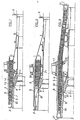
- La figure 1 représente un exemple de réalisation de la structure de rétention vue en demi-coupe longitudinale.
- La figure 2 est un second exemple de réalisation de la structure.
- La figure 3 est un exemple d'utilisation de la structure de rétention comme élément structurel du carter.
- FIG. 1 represents an exemplary embodiment of the retention structure seen in longitudinal half-section.
- Figure 2 is a second embodiment of the structure.
- FIG. 3 is an example of use of the retention structure as a structural element of the casing.
La structure de rétention 1, représentée figure 1, est fixée à ses extrémités par l'intermédiaire des brides 2 et 3 à la manche à air et au carter moteur (non représentés). Cette structure dépasse en avant et en arrière la zone L balayée par les aubes du rotor 4. Face aux aubes du rotor, un anneau d'étanchéité 11 est fixé sur la structure. Cet anneau est constitué d'un support 12 revêtu d'une couche d'usure 13 et il peut être amovible, le support 12 étant monobloc.The
La structure de rétention comporte, selon cet exemple de réalisation, une couche extérieure 5 et une couche intérieure 6. La couche intérieure est constituée d'une structure sandwich, formée d'une peau intérieure 7, métallique, collée sur une structure en nid d'abeilles 8, recouverte sur l'extérieur par une peau 9 en résine synthétique éventuellement armée d'un tissu de fibres de verre ou autres. La structure en nid d'abeilles est renforcée par la couche extérieure 5 en matériau composite fibreux, constituée par exemple de couches de fibres suivant la désignation commerciale Kevlar ou d'un bobinage de fibres polyimide immobilisé dans une résine synthétique.The retention structure comprises, according to this embodiment, an
La peau métallique 7 est renforcée en 14 dans le plan de l'aubage 4 de manière à pouvoir supporter l'effet de tronçonnage.The
Cette partie renforcée permet également le maintien des tôles intérieures 10 définissant le profil aérodynamique du conduit.This reinforced part also makes it possible to maintain the
La structure en nid d'abeilles 8 peut être remplacée en équivalence par une structure en fibres jouant le même rôle.The
Dans les figures suivantes, les éléments semblables portent les mêmes références.In the following figures, similar elements have the same references.
La figure 2 montre un deuxième exemple de réalisation de la structure. Cette réalisation diffère de la précédente par une peau intérieure 71 en matériau composite et une partie renforcée,portée par une peau extérieure 90 et constituée par une nervure métallique 15 dont une extrémité est prolongée par une aile et se trouve en face de l'aubage. La peau extérieure 90 métallique porte à ses extrémités les brides 2 et 3.Figure 2 shows a second embodiment of the structure. This embodiment differs from the previous one by an
Dans la figure 3, la fonction structure 6 est assurée par un matériau sandwich constitué par deux peaux 91 et 72 en matériau composite collées sur une âme du type nid d'abeilles 8. Des brides métalliques 21 et 31 collées à chaque extrémité de la structure assurent les liaisons manche à air-structure de rétention et structure de rétention-carter. La bride avant 21 est prolongée à sa partie intérieure 16 et protège la structure contre l'effet de tronçonnage. Ce prolongement intérieur est renforcé en 14 dans le plan de l'aubage 4 et permet, en outre, le centrage de l'anneau d'étancheité 11. Comme le montre la figure, le prolongement intérieur de la bride s'étend au-delà de l'aubage, afin de constituer une protection contre les fragments éjectés dans un plan non parallèle au plan de rotation de l'aubage, et de permettre une fixation particulièrement rigide du support d'accessoires 17 au moyen de tirants 18.In FIG. 3, the
Cette troisième forme de réalisation de structure de rétention présente l'avantage d'être auto-portante et de constituer un segment indépendant.This third embodiment of the retention structure has the advantage of being self-supporting and of constituting an independent segment.
Claims (12)
caractérisée en ce qu'elle comporte successivement, dans la direction radiale, de l'intérieur vers l'extérieur :
characterized in that it successively comprises, in the radial direction, from the inside to the outside:
Applications Claiming Priority (2)
| Application Number | Priority Date | Filing Date | Title |
|---|---|---|---|
| FR7929114A FR2470269A1 (en) | 1979-11-27 | 1979-11-27 | RETENTION STRUCTURE FOR A COMPRESSOR CASE OF A TURBOMACHINE |
| FR7929114 | 1979-11-27 |
Publications (2)
| Publication Number | Publication Date |
|---|---|
| EP0030179A1 true EP0030179A1 (en) | 1981-06-10 |
| EP0030179B1 EP0030179B1 (en) | 1984-10-17 |
Family
ID=9232107
Family Applications (1)
| Application Number | Title | Priority Date | Filing Date |
|---|---|---|---|
| EP80401625A Expired EP0030179B1 (en) | 1979-11-27 | 1980-11-13 | Retaining structure for the compressor housing of a turbo engine |
Country Status (3)
| Country | Link |
|---|---|
| EP (1) | EP0030179B1 (en) |
| DE (1) | DE3069465D1 (en) |
| FR (1) | FR2470269A1 (en) |
Cited By (16)
| Publication number | Priority date | Publication date | Assignee | Title |
|---|---|---|---|---|
| FR2502696A1 (en) * | 1981-03-25 | 1982-10-01 | Rolls Royce | GAS TURBINE ENGINE HAVING INCREASED IMMUNITY TO DAMAGE CAUSED BY INGESTION OF FOREIGN BODIES |
| FR2547357A1 (en) * | 1983-06-09 | 1984-12-14 | Snecma | RETENTION STRUCTURE FOR TURBOMACHINE HOUSING |
| GB2159886A (en) * | 1984-06-07 | 1985-12-11 | Rolls Royce | Fan duct casing |
| FR2574476A1 (en) * | 1984-12-06 | 1986-06-13 | Snecma | RETENTION HOUSING FOR TURBOJET BLOWER |
| US4598449A (en) * | 1981-12-21 | 1986-07-08 | United Technologies Corporation | Beam for a containment structure |
| US4718818A (en) * | 1981-12-21 | 1988-01-12 | United Technologies Corporation | Containment structure |
| US5160248A (en) * | 1991-02-25 | 1992-11-03 | General Electric Company | Fan case liner for a gas turbine engine with improved foreign body impact resistance |
| EP0513958A3 (en) * | 1991-05-13 | 1993-01-13 | General Electric Company | Composite fan stator assembly |
| GB2288639A (en) * | 1994-04-20 | 1995-10-25 | Rolls Royce Plc | Blade containment in a ducted fan gas turbine engine nacelle assembly |
| WO2000046489A1 (en) * | 1999-02-04 | 2000-08-10 | Pratt & Whitney Canada Corp. | Hardwall fan case with structured bumper |
| US8434995B2 (en) | 2009-05-05 | 2013-05-07 | Rolls-Royce Plc | Duct wall for a fan of a gas turbine engine |
| CN103154524A (en) * | 2010-08-11 | 2013-06-12 | 航空技术空间股份有限公司 | Axial turbomachine compressor outer casing |
| CN103154524B (en) * | 2010-08-11 | 2016-11-30 | 赛峰航空助推器股份有限公司 | The shell of axial turbomachine compressor |
| EP3106289A1 (en) * | 2015-06-17 | 2016-12-21 | Kling, Colin J. | Co-molded metallic fan case containment ring |
| CN109882449A (en) * | 2019-03-22 | 2019-06-14 | 中国航发常州兰翔机械有限责任公司 | A kind of aero-engine compressor front cover |
| CN114017141A (en) * | 2021-11-05 | 2022-02-08 | 中国航发沈阳发动机研究所 | Rotor-stator casing |
Citations (10)
| Publication number | Priority date | Publication date | Assignee | Title |
|---|---|---|---|---|
| FR1189849A (en) * | 1955-08-18 | 1959-10-07 | Stromungsmaschinen Ges M B H A | Fixed crown for gas turbine rotor |
| US2999667A (en) * | 1956-09-28 | 1961-09-12 | Rolls Royce | Protective arrangement for use with apparatus or machines having rotating parts |
| FR1429834A (en) * | 1964-05-08 | 1966-02-25 | Rolls Royce | Improvements made to blades, particularly for gas turbine engines |
| FR1534297A (en) * | 1966-11-23 | 1968-07-26 | Gen Electric | Sealing device for turbomachines |
| US3867060A (en) * | 1973-09-27 | 1975-02-18 | Gen Electric | Shroud assembly |
| FR2282537A1 (en) * | 1974-08-23 | 1976-03-19 | Rolls Royce | TURBOMOTOR CASINGS |
| FR2290350A1 (en) * | 1974-11-08 | 1976-06-04 | Gen Electric | NACELLE FOR GAS TURBINE ENGINE |
| US4055041A (en) * | 1974-11-08 | 1977-10-25 | The United States Of America As Represented By The Administrator Of The National Aeronautics And Space Administration | Integrated gas turbine engine-nacelle |
| FR2375443A1 (en) * | 1976-12-23 | 1978-07-21 | Gen Electric | TURBOMACHINE BLADE RETAINER |
| GB2010434A (en) * | 1977-12-16 | 1979-06-27 | Rolls Royce | Bolted, Flanged Joint |
Family Cites Families (1)
| Publication number | Priority date | Publication date | Assignee | Title |
|---|---|---|---|---|
| FR2467977A1 (en) * | 1979-10-19 | 1981-04-30 | Snecma | SAFETY DEVICE IN THE EVENT OF TURBOMACHINE ROTATING ELEMENT BREAK |
-
1979
- 1979-11-27 FR FR7929114A patent/FR2470269A1/en active Granted
-
1980
- 1980-11-13 EP EP80401625A patent/EP0030179B1/en not_active Expired
- 1980-11-13 DE DE8080401625T patent/DE3069465D1/en not_active Expired
Patent Citations (11)
| Publication number | Priority date | Publication date | Assignee | Title |
|---|---|---|---|---|
| FR1189849A (en) * | 1955-08-18 | 1959-10-07 | Stromungsmaschinen Ges M B H A | Fixed crown for gas turbine rotor |
| US2999667A (en) * | 1956-09-28 | 1961-09-12 | Rolls Royce | Protective arrangement for use with apparatus or machines having rotating parts |
| FR1429834A (en) * | 1964-05-08 | 1966-02-25 | Rolls Royce | Improvements made to blades, particularly for gas turbine engines |
| FR1534297A (en) * | 1966-11-23 | 1968-07-26 | Gen Electric | Sealing device for turbomachines |
| US3867060A (en) * | 1973-09-27 | 1975-02-18 | Gen Electric | Shroud assembly |
| FR2245852A1 (en) * | 1973-09-27 | 1975-04-25 | Gen Electric | |
| FR2282537A1 (en) * | 1974-08-23 | 1976-03-19 | Rolls Royce | TURBOMOTOR CASINGS |
| FR2290350A1 (en) * | 1974-11-08 | 1976-06-04 | Gen Electric | NACELLE FOR GAS TURBINE ENGINE |
| US4055041A (en) * | 1974-11-08 | 1977-10-25 | The United States Of America As Represented By The Administrator Of The National Aeronautics And Space Administration | Integrated gas turbine engine-nacelle |
| FR2375443A1 (en) * | 1976-12-23 | 1978-07-21 | Gen Electric | TURBOMACHINE BLADE RETAINER |
| GB2010434A (en) * | 1977-12-16 | 1979-06-27 | Rolls Royce | Bolted, Flanged Joint |
Cited By (26)
| Publication number | Priority date | Publication date | Assignee | Title |
|---|---|---|---|---|
| FR2502696A1 (en) * | 1981-03-25 | 1982-10-01 | Rolls Royce | GAS TURBINE ENGINE HAVING INCREASED IMMUNITY TO DAMAGE CAUSED BY INGESTION OF FOREIGN BODIES |
| US4598449A (en) * | 1981-12-21 | 1986-07-08 | United Technologies Corporation | Beam for a containment structure |
| US4718818A (en) * | 1981-12-21 | 1988-01-12 | United Technologies Corporation | Containment structure |
| FR2547357A1 (en) * | 1983-06-09 | 1984-12-14 | Snecma | RETENTION STRUCTURE FOR TURBOMACHINE HOUSING |
| EP0128819A1 (en) * | 1983-06-09 | 1984-12-19 | Societe Nationale D'etude Et De Construction De Moteurs D'aviation, "S.N.E.C.M.A." | Containment structure for the housing of a turbo machine |
| US4705454A (en) * | 1983-06-09 | 1987-11-10 | Societe Nationale D'etude Et De Construction De Moteurs D'aviation | Turbomachine casing with containment structure intended to contain fractured rotating parts |
| GB2159886A (en) * | 1984-06-07 | 1985-12-11 | Rolls Royce | Fan duct casing |
| US4699567A (en) * | 1984-06-07 | 1987-10-13 | Rolls-Royce Plc | Fan duct casing |
| FR2574476A1 (en) * | 1984-12-06 | 1986-06-13 | Snecma | RETENTION HOUSING FOR TURBOJET BLOWER |
| EP0184962A1 (en) * | 1984-12-06 | 1986-06-18 | Societe Nationale D'etude Et De Construction De Moteurs D'aviation, "S.N.E.C.M.A." | Retention housing for a turbo fan |
| US5160248A (en) * | 1991-02-25 | 1992-11-03 | General Electric Company | Fan case liner for a gas turbine engine with improved foreign body impact resistance |
| US5226789A (en) * | 1991-05-13 | 1993-07-13 | General Electric Company | Composite fan stator assembly |
| EP0513958A3 (en) * | 1991-05-13 | 1993-01-13 | General Electric Company | Composite fan stator assembly |
| GB2288639A (en) * | 1994-04-20 | 1995-10-25 | Rolls Royce Plc | Blade containment in a ducted fan gas turbine engine nacelle assembly |
| US5516258A (en) * | 1994-04-20 | 1996-05-14 | Rolls-Royce Plc | Ducted fan gas turbine engine nacelle assembly |
| GB2288639B (en) * | 1994-04-20 | 1998-10-21 | Rolls Royce Plc | Ducted fan gas turbine engine nacelle assembly |
| WO2000046489A1 (en) * | 1999-02-04 | 2000-08-10 | Pratt & Whitney Canada Corp. | Hardwall fan case with structured bumper |
| US6149380A (en) * | 1999-02-04 | 2000-11-21 | Pratt & Whitney Canada Corp. | Hardwall fan case with structured bumper |
| US8434995B2 (en) | 2009-05-05 | 2013-05-07 | Rolls-Royce Plc | Duct wall for a fan of a gas turbine engine |
| CN103154524A (en) * | 2010-08-11 | 2013-06-12 | 航空技术空间股份有限公司 | Axial turbomachine compressor outer casing |
| CN103154524B (en) * | 2010-08-11 | 2016-11-30 | 赛峰航空助推器股份有限公司 | The shell of axial turbomachine compressor |
| EP3106289A1 (en) * | 2015-06-17 | 2016-12-21 | Kling, Colin J. | Co-molded metallic fan case containment ring |
| US10458433B2 (en) | 2015-06-17 | 2019-10-29 | United Technologies Corporation | Co-molded metallic fan case containment ring |
| US11236765B2 (en) | 2015-06-17 | 2022-02-01 | Raytheon Technologies Corporation | Co-molded metallic fan case containment ring |
| CN109882449A (en) * | 2019-03-22 | 2019-06-14 | 中国航发常州兰翔机械有限责任公司 | A kind of aero-engine compressor front cover |
| CN114017141A (en) * | 2021-11-05 | 2022-02-08 | 中国航发沈阳发动机研究所 | Rotor-stator casing |
Also Published As
| Publication number | Publication date |
|---|---|
| EP0030179B1 (en) | 1984-10-17 |
| FR2470269A1 (en) | 1981-05-29 |
| DE3069465D1 (en) | 1984-11-22 |
| FR2470269B1 (en) | 1983-12-09 |
Similar Documents
| Publication | Publication Date | Title |
|---|---|---|
| EP0184962B1 (en) | Retention housing for a turbo fan | |
| EP0030179A1 (en) | Retaining structure for the compressor housing of a turbo engine | |
| EP0128819B1 (en) | Containment structure for the housing of a turbo machine | |
| EP2053200B1 (en) | Control of the blade tip clearance of the high-pressure turbine of a turbomachine | |
| EP0027756A1 (en) | Safety device in case of rupture of a rotating turbomachine part | |
| EP3109406B1 (en) | Axial turbomachine compressor casing | |
| WO2010072968A1 (en) | Turbine engine rotor wheel with blades made of a composite material provided with a spring ring | |
| EP2886804B1 (en) | Sealing device for a compressor of a turbomachine | |
| FR2943984A1 (en) | Propeller for turbine engine e.g. open rotor type turbine engine, of aircraft, has hub comprising two annular type portions that are fixed to each other and defining part of recess opening | |
| WO2022096822A1 (en) | Assembly for a turbomachine | |
| FR2956875A1 (en) | Blade for use in casing of turbomachine of double flow airplane, has two plates made of draped composite material, where one of plates forms lower surface of blade and other plate forms upper surface of blade | |
| FR2988426A1 (en) | Inter blade platform for fan of e.g. turbo jet engine, of aircraft, has upstream end portion and/or downstream end portion provided with upstream and downstream wings prolonging wall, and assembly flanges extended axially beyond wings | |
| EP2427659B1 (en) | Stator shroud of aircraft turbine engine with slots for relieving mechanical stress on blades | |
| FR2940359A1 (en) | Exhaust casing for turbine engine of engine assembly of aircraft, has structural unit passed through exterior shell in manner to locally authorize relative displacement of unit between integrated assembly and shell | |
| WO2021048473A1 (en) | Attachment of an acoustic shroud to a housing shell for an aircraft turbine engine | |
| EP2886802A1 (en) | Gasket of the inner ferrule of the last stage of an axial turbomachine compressor | |
| EP3867509B1 (en) | Improved air-sealing device intended to be inserted between an aircraft dual-flow turbine engine casing element and a nacelle element | |
| EP3918204A1 (en) | Fan casing for an aircraft turbomachine | |
| EP3717749B1 (en) | Assembly for axial turbomachine, associated assembly method and seals | |
| FR2672943A1 (en) | Turbomachine compressor equipped with a device for drawing off air | |
| FR2968636A1 (en) | AIR INTAKE FOR AIRCRAFT PROPULSIVE ASSEMBLY HAVING A SURPRISING RESISTANT STRUCTURE AND METHOD FOR REPAIRING AN AIRCRAFT PROPULSIVE ASSEMBLY AIR INTAKE | |
| EP3921526B1 (en) | Turbomachine fan | |
| EP4143421A1 (en) | Intermediate flow-straightening casing with monobloc structural arm | |
| FR2953252A1 (en) | Distribution sector for low pressure turbine of e.g. turbojet of airplane, has outer platform sector comprising stiffeners located in extension of vanes and extended along axis parallel to tangent at upstream and downstream edges of vanes | |
| FR3100834A1 (en) | TURBOMACHINE ACOUSTIC ANNULAR VIROLE AND ASSOCIATED MANUFACTURING PROCESS |
Legal Events
| Date | Code | Title | Description |
|---|---|---|---|
| PUAI | Public reference made under article 153(3) epc to a published international application that has entered the european phase |
Free format text: ORIGINAL CODE: 0009012 |
|
| 17P | Request for examination filed |
Effective date: 19801119 |
|
| AK | Designated contracting states |
Designated state(s): DE FR GB |
|
| GRAA | (expected) grant |
Free format text: ORIGINAL CODE: 0009210 |
|
| AK | Designated contracting states |
Designated state(s): DE FR GB |
|
| REF | Corresponds to: |
Ref document number: 3069465 Country of ref document: DE Date of ref document: 19841122 |
|
| PLBE | No opposition filed within time limit |
Free format text: ORIGINAL CODE: 0009261 |
|
| STAA | Information on the status of an ep patent application or granted ep patent |
Free format text: STATUS: NO OPPOSITION FILED WITHIN TIME LIMIT |
|
| 26N | No opposition filed | ||
| PGFP | Annual fee paid to national office [announced via postgrant information from national office to epo] |
Ref country code: FR Payment date: 19921023 Year of fee payment: 13 |
|
| PGFP | Annual fee paid to national office [announced via postgrant information from national office to epo] |
Ref country code: GB Payment date: 19921102 Year of fee payment: 13 |
|
| PGFP | Annual fee paid to national office [announced via postgrant information from national office to epo] |
Ref country code: DE Payment date: 19930129 Year of fee payment: 13 |
|
| PG25 | Lapsed in a contracting state [announced via postgrant information from national office to epo] |
Ref country code: GB Effective date: 19931113 |
|
| GBPC | Gb: european patent ceased through non-payment of renewal fee |
Effective date: 19931113 |
|
| PG25 | Lapsed in a contracting state [announced via postgrant information from national office to epo] |
Ref country code: FR Effective date: 19940729 |
|
| PG25 | Lapsed in a contracting state [announced via postgrant information from national office to epo] |
Ref country code: DE Effective date: 19940802 |
|
| REG | Reference to a national code |
Ref country code: FR Ref legal event code: ST |