EP0030131B1 - Process and apparatus for mechanical separation of a combination of meat and bone into useful fractions - Google Patents
Process and apparatus for mechanical separation of a combination of meat and bone into useful fractions Download PDFInfo
- Publication number
- EP0030131B1 EP0030131B1 EP80304266A EP80304266A EP0030131B1 EP 0030131 B1 EP0030131 B1 EP 0030131B1 EP 80304266 A EP80304266 A EP 80304266A EP 80304266 A EP80304266 A EP 80304266A EP 0030131 B1 EP0030131 B1 EP 0030131B1
- Authority
- EP
- European Patent Office
- Prior art keywords
- combination
- screw
- meat
- bone
- conduit
- Prior art date
- Legal status (The legal status is an assumption and is not a legal conclusion. Google has not performed a legal analysis and makes no representation as to the accuracy of the status listed.)
- Expired
Links
- 210000000988 bone and bone Anatomy 0.000 title claims abstract description 61
- 235000013372 meat Nutrition 0.000 title claims abstract description 51
- 238000000034 method Methods 0.000 title claims abstract description 12
- 238000000926 separation method Methods 0.000 title claims abstract description 12
- 230000033001 locomotion Effects 0.000 claims description 7
- 230000000717 retained effect Effects 0.000 claims description 4
- 238000007599 discharging Methods 0.000 claims description 3
- 230000010006 flight Effects 0.000 claims description 2
- 238000003825 pressing Methods 0.000 claims description 2
- 239000012530 fluid Substances 0.000 claims 2
- 230000007423 decrease Effects 0.000 description 6
- 241000239290 Araneae Species 0.000 description 5
- 238000010008 shearing Methods 0.000 description 4
- 239000000428 dust Substances 0.000 description 3
- 238000004140 cleaning Methods 0.000 description 2
- 238000010276 construction Methods 0.000 description 2
- 230000000694 effects Effects 0.000 description 2
- 238000004519 manufacturing process Methods 0.000 description 2
- 239000000463 material Substances 0.000 description 2
- 239000002184 metal Substances 0.000 description 2
- 241000251468 Actinopterygii Species 0.000 description 1
- 241000287828 Gallus gallus Species 0.000 description 1
- 241001465754 Metazoa Species 0.000 description 1
- 230000001154 acute effect Effects 0.000 description 1
- 235000015278 beef Nutrition 0.000 description 1
- 230000006835 compression Effects 0.000 description 1
- 238000007906 compression Methods 0.000 description 1
- 230000003247 decreasing effect Effects 0.000 description 1
- 230000006866 deterioration Effects 0.000 description 1
- 235000013305 food Nutrition 0.000 description 1
- 238000010438 heat treatment Methods 0.000 description 1
- 239000010720 hydraulic oil Substances 0.000 description 1
- 230000000670 limiting effect Effects 0.000 description 1
- 235000013622 meat product Nutrition 0.000 description 1
- 230000036961 partial effect Effects 0.000 description 1
- 235000015277 pork Nutrition 0.000 description 1
- 230000007425 progressive decline Effects 0.000 description 1
- 235000020989 red meat Nutrition 0.000 description 1
- 230000002829 reductive effect Effects 0.000 description 1
- 125000006850 spacer group Chemical group 0.000 description 1
Images



Classifications
-
- A—HUMAN NECESSITIES
- A22—BUTCHERING; MEAT TREATMENT; PROCESSING POULTRY OR FISH
- A22C—PROCESSING MEAT, POULTRY, OR FISH
- A22C17/00—Other devices for processing meat or bones
- A22C17/04—Bone cleaning devices
Definitions
- This invention relates to processes and apparatus for mechanical separation of a combination of meat and bone into useful fractions.
- bone dust that has been produced by shearing action as the combination is moved by the feed screw across the face of the screen, and at the same time is forced under high pressure against the screen to express the meat through its apertures.
- this pressure may be as high as 85 kg.s.cm (1200 p.s.i.), which is high enough to shear off pieces of bone small enough to pass through the screen apertures as the bone is moved over the screen surface. It is therefore a constant endeavour to reduce this pressure and also to provide that the bones are broken cleanly without any shearing thereof.
- apparatus for the mechanical separation of meat and bone into separate fractions thereof comprising:
- the part of the apparatus of Figure 1A comprises a base indicated generally by the reference 10 in which a drive motor (not shown) is mounted.
- a casing 12 On the top of the base is mounted a casing 12 providing a hopper 14 for the reception of the meat and bone combination to be separated.
- the casing 12 has fastened thereto a tubular casing 16 providing a passage 18 and having mounted therein a conveyor screw 20, the screw being rotatable about a horizontal longitudinal axis.
- the rear end of the screw 20 has a splined recess and is in rotational driving engagement with a splined boss 22 mounted in the casing by a bearing 24; a seal 26 is also provided.
- This boss is constituted by the free end of output shaft 28 of a speed reduction gear 30, the input to the speed reduction gear being via a suitable drive from the above- mentioned drive motor.
- the body of the conveyor screw 20 adjacent the hopper 14 and into the passage 18 is of uniform diameter and then decreases progressively in diameter, this decrease starting inside the passage 18 and continuing to the end of the screw.
- the body is provided with a thread 32 which decreases progressively in pitch to apply a corresponding progressively increasing pressure to the entrained combination.
- the cylindrical internal wall of part 16 is provided with another stationary screw thread 34 of opposite hand to the screw thread 32, and this thread 34 continues with progressively decreasing pitch and diameter on the inner cylindrical tapered wall of a corresponding part 36.
- the threads 32 and 34 form between themselves a throat of progressively reducing diameter in which the bones in the combination are broken relatively cleanly before they are forced by the conveyor screw through openings 38 in a spider 40, and into the separating section. It will be noted that at the outlet from this throat the two threads 32 and 34 are almost touching so that the bones are broken into relatively small pieces.
- a bone breaking arrangement of the kind employed in the apparatus of this invention results in much lower bone contents in the meat fraction than is obtainable in prior art apparatus in which the bones are broken by the shearing action of a knife blade rotating against an apertured plate through which the combination passes.
- This less satisfactory result of such prior art apparatus is believed due to the fundamental construction of animal bone.
- bone is of relatively porous structure and the action of the shearing knife blade on such material while it is jammed against the usual apertured breaker plate is to crumble it and form relatively large amounts of bone dust that can pass easily through the separator screen with the meat fraction.
- the bone breaking apparatus of this invention breaks the bones cleanly with a considerable reduction in the production of such dust.
- the part 36 is held in place in a counterbore in the body part 16 by an annular nut 42 screw-threaded around its outer periphery. Upon removal of the nut 42 the part 16 and the conveyor screw 20 can be removed for the disassembly and cleaning that is an essential and continuing item in the servicing of any apparatus employed for the processing of food.
- the other parts of the machine that are contacted by the combination are also arranged for such convenient disassembly for this purpose.
- the end of the conveyor screw 20 at the outlet of the bone breaking throat is provided with a splined recess receiving a splined connecting shaft 44 that passes through a plain thrust bearing 46 in the spider 38.
- the splined connector 42 is engaged in the adjacent end of a feed screw 48 mounted for rotation about a longitudinal axis coaxial with that of the conveyor screw 20.
- the separator portion of the apparatus body mounting the feed screw consists of two longitudinally spaced end plates 50 and 52 connected together by three circumferentially spaced tie rods 54, the end plate 50 being clamped to the casing 16 by an annular clamp ring 56.
- the other end 58 of the feed screw is supported by a plain bearing 60 having the form of an axially-apertured spider, the bearing being mounted in an axially- movable annular part 62 which is in turn mounted by a tubular extension of the end plate 52 for such movement, as will be described below.
- a separator screen forms a cylindrical conduit providing an annular bore 66, the screen surrounding the feed screw member to separate into different fractions the pressurized combination of meat and bone fed thereto by the screw 20 through the spider apertures 38.
- the screen is constituted by a stack of a large number of plain annular discs 68 ( Figure 3), alternating with configured annular discs 70 ( Figure 2), which are clamped tightly face-to- face by the tie rods 54, and are held in circumferential alignment with one another by a set of six equally-circumferentially-spaced rectangular cross-section longitudinal bars 72 extending between the end plates 50 and 52 and connected to the plate 50 by bolts 74.
- the plain discs 68 are of uniform thickness and provided with six equally-circumferentially-spaced rectangular slots 76 to receive the bars 72.
- the configured discs 70 are also provided with rectangular slots 78 to receive the bars, but they are cut away to provide recesses in each annular face at 80, leaving a central web 82 of reduced thickness, spacer portions 84 surrounding each slot 78 and slotted annular radially-inner ring 86.
- Slots such as 88 in the ring 86 are in this embodiment inclined at an angle of about 150° to the respective radius, the inclination being opposite to the direction of rotation of the feed screw 28. In other embodiments this angle may vary from about 165° to about 120°.
- each sandwich of two plain discs 68 with an interposed configured disc 70 provides two circumferential rows each of a large number of small rectangular cross-section bores 88 constituted by the slots, these bores discharging radially and circumferentially from the separator space 66, each row feeding into a respective radially- outer narrow single circumferential slot formed by the recessed portion 80 of the disc.
- the metal part that remains between each immediately adjacent pair of slots/bores is of parallelepiped shape and because of the inclination of the slots/bores in the direction opposite to that of the rotation of the feed-screw each of these metal parts presents an obtuse-angled blunt edge such as 90 to the meat/bone combination in the space 66.
- Such a blunt edge avoids removal from the bone of slivers that are able to pass through the bores 88 to increase the bone content of the meat fraction, as is likely to happen if this angle is acute or even a right angle.
- the design of the screw thread 92 of the feed screw is such that the rotation of the screw produces a radially-outwardly-acting pressure force on the combination in the cylindrical conduit provided by the screen 64.
- This conduit is of uniform internal diameter and the screw lands are of substantially uniform external radius centered on the longitudinal axis of the conduit so that they terminate close to the screen interior surface with a narrow gap of uniform height between them, but it will be observed from Figure 1 B that, in the direction of flow of the meat/bone combination therein from the inlet of the conduit to its outlet, the body of the screw between each immediately succeeding pair of flight lands increases progressively in radius from a minimum value at the forward root of the rear land of the screw to a maximum value at the rear root of the next forward land, the screw body profile between the roots being a straight line and, in particular, is not concave.
- FIG. 5 also illustrates the screw profile provided in this embodiment to obtain the pulsating force.
- the transverse cross-section of the screw body is circular and it remains circular throughout its length, while the centre of the circular cross-section describes a circular orbit about the longitudinal axis, as indicated by the broken line bearing the reference 94, this circle being described over the distance between each immediately successive pair of lands.
- the path of the circle cross-section is therefore a helix of uniform radius but changing pitch.
- a circular cross-section and a circular orbit are employed to simplify as much as possible the production of what is already a complex profile to form.
- the required compensation for the loss of meat fraction through the screen is produced by progressive decrease of the pitch of the screw thread, the decrease being that calculated to provide as much as is possible a substantially constant pressure in the separating material.
- the body of the feed screw 48 decreases progressively and rapidly in diameter and is provided with a high pitch shallow thread 95, while the cooperating tapered face 96 of the tubular member 62 is provided with a high pitch shallow thread 98 of opposite hand to apply back pressure to the exiting bone fraction.
- the bone fraction that emerges from the tapered throat formed between the two threads 94 and 98 is moved by thread 100 on the small diameter feed screw end portion out through exit ports 102 in the spider member 60 to apparatus outlet 104.
- tubular part 62 is mounted for axial sliding movement in a cylindrical portion 106 extending from the end plate 52, the part 62 abutting against an annular piston 108 mounted in a cylinder formed between two parts 110 and 112.
- the part 110 is mounted for axial sliding and rotating movement on the end of the part 62, while the part 112 surrounds the adjacent end of the cylindrical portion 106, and is in screw-threaded engagement therewith, so that axial rotation of parts 110 and 112 also moves them axially to change the volume of cylinder chamber 114.
- the chamber 114 is filled with a hydraulic oil supplied via a pipe 116 from an air/hydraulic multiplier 118 that is in turn supplied with compressed air via a pipeline 102 through controllable pressure reducing valve 122.
- This structure constitutes a controllable hydraulic spring means urging the member 62 to the right as seen in Figure 1 B so as to close the throat gap between the threads 94 and 98 and maintain the average pressure applied to the separating meat/bone combination at a value corresponding to the applied spring pressure.
- the piston 108 is able to move the member 62 further to the right, closing the throat and thereby holding back the exiting separated bone fraction until the pressure has increased again.
- the part 62 will move to open the throat gap, so that the bone fraction can flow more quickly and pressure decreases back to the predetermined value.
- a change between different meats to be processed simply requires therefore an adjustment of the axial position of the part 112 by rotation thereof and/or an adjustment of the valve 122 until the desired conditions are obtained.
- the hydraulic spring could be replaced by a mechanical compression spring system of the required rate and compressive strength, but in commercial practice a hydraulic system is easier to adjust over the range of forces and movements required.
- each plain disc 68 is 1.5 mm and is not of course particularly critical, while the thickness of each configured disc 70 is 5 mm and can vary between about 3 and 6.5 mm.
- each disc 70 is recessed at 80 to a depth of 1 mm on each side, and consequently the larger circumferential slot is of this width; this dimension will usually change with the thickness of the configured disc and will usually be in the range 1-2 mm for the specified range of ring thicknesses.
- the slots/bores 88 are much narrower and will usually measure about 0.3 mm to 0.4 mm in corresponding dimension so that there is an immediate pressure drop as the separated meat exits from the slots/bores 88 into the wider circumferential slot 80.
- Their circumferential width can be the same, but usually will be larger, of the order of 0.5 mm to 1.5 mm.
Landscapes
- Life Sciences & Earth Sciences (AREA)
- Engineering & Computer Science (AREA)
- Wood Science & Technology (AREA)
- Zoology (AREA)
- Food Science & Technology (AREA)
- Meat, Egg Or Seafood Products (AREA)
- Crushing And Pulverization Processes (AREA)
Abstract
Description
- This invention relates to processes and apparatus for mechanical separation of a combination of meat and bone into useful fractions.
- Prior examples of such apparatus are found for example in U.S. Patent No. 3739994, U.S. Patent No. 3741772, U.S. Patent No. 3906118, U.S. Patent No. 3398676, U.S. Patent No. 3398677, U.S. Patent No. 1785041, U.S. Patent No. 1930189, U.S. Patent No. 1772262, French Patent No. 46408 (First addition to No. 764386), and U.S. Patents Nos. 4025001 and 4069980.
- It is the object of all the processes and apparatus disclosed in these patents to separate a random combination of meat and bone into useful fractions. In practice it is impossible to effect a complete separation and it is a constant endeavour to provide one fraction that is as high as possible in meat content and as low as possible in bone content, while the other fraction is as high as possible in bone content and as low as possible in meat content. Many authorities now place a strict upper limit on the bone content of meat derived from a process of mechanical separation.
- It is found that one of the principal sources of bone content in the meat fraction is bone dust that has been produced by shearing action as the combination is moved by the feed screw across the face of the screen, and at the same time is forced under high pressure against the screen to express the meat through its apertures. In some prior art apparatus this pressure may be as high as 85 kg.s.cm (1200 p.s.i.), which is high enough to shear off pieces of bone small enough to pass through the screen apertures as the bone is moved over the screen surface. It is therefore a constant endeavour to reduce this pressure and also to provide that the bones are broken cleanly without any shearing thereof.
- It is therefore an object of the invention to provide a new process and new apparatus for mechanical separation of meat and bone into useful fractions.
- In accordance with the present invention there is provided a process for the mechanical separation of meat and bone into separate fractions thereof comprising the steps of:
- a) providing a cylindrical conduit having an inlet end and an outlet end and containing a feed screw having a plurality of successive flights and rotatable about a longitudinal axis, at least part of the wall of the conduit surrounding the feed screw cbmprising a separator screen for separating the meat and bone fractions,
- b) introducing the meat and bone combination to be separated into the inlet end of the conduit,
- c) operating the feed screw to move the combination through the conduit from the inlet end to the outlet end under pressure which is operative radially outwardly against the separator screen so as to force the meat fraction through the separator screen while the bone fraction is retained thereby and moved through the conduit to the outlet end,
- d) discharging the bone fraction from the outlet end and the meat fraction from the separator screen, the process being characterized by:
- e) the operation of the feed screw applies a radially outwardly pulsating pressure force to the combination.
- Also in accordance with the present invention there is provided apparatus for the mechanical separation of meat and bone into separate fractions thereof comprising:
- a) a cylindrical conduit having an inlet end and an outlet end and containing a feed screw rotatable about a longitudinal axis,
- b) the feed screw comprising a plurality of successive lands and upon rotation about its axis moving a meat and bone combination to be separated along the conduit from the inlet to the. outlet and applying radially outwardly operative pressure to the combination pressing it against the conduit wall,
- c) at least part of the conduit wall comprising a separator screen whereby the pressure of the combination against the screen part forces the meat fraction through the screen while the bone fraction is retained thereby and moved through the conduit to the outlet end, characterised in that
- d) the screw is shaped so that the said rotation of the screw applies a radially outwardly pulsating pressure force to the combination.
- Processes and apparatus for the mechanical separation of meat and bone into useful fractions which are particular preferred embodiments of the invention will now be described, by way of example, with reference to the accompanying diagrammatic drawings, wherein:
- Figures 1A and 1B together are a longitudinal cross-section of the apparatus;
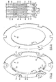
- Figure 2 is a perspective view of a configured annular plate used in the apparatus of Figures 1A and 1 B, one part being broken away to show the cross-section;
- Figure 3 is a similar view of one form of plain annular plate as used in the apparatus of Figures 1A and 1B;
- Figure 4 is a partial section of a portion of a stack of plates as would be seen taken along lines 4-4 of Figures 2 and 3; and
- Figure 5 is a cross-section taken on the line 5-5 of Figure 1 B.
- The part of the apparatus illustrated in Figure 1 A is a feed and pressurising section, and will be described first, while the part illustrated in Figure 1 B is the separating section, and will be described thereafter.
- The part of the apparatus of Figure 1A comprises a base indicated generally by the
reference 10 in which a drive motor (not shown) is mounted. On the top of the base is mounted acasing 12 providing ahopper 14 for the reception of the meat and bone combination to be separated. Thecasing 12 has fastened thereto atubular casing 16 providing apassage 18 and having mounted therein aconveyor screw 20, the screw being rotatable about a horizontal longitudinal axis. The rear end of thescrew 20 has a splined recess and is in rotational driving engagement with asplined boss 22 mounted in the casing by abearing 24; aseal 26 is also provided. This boss is constituted by the free end ofoutput shaft 28 of aspeed reduction gear 30, the input to the speed reduction gear being via a suitable drive from the above- mentioned drive motor. - The body of the conveyor screw 20 adjacent the
hopper 14 and into thepassage 18 is of uniform diameter and then decreases progressively in diameter, this decrease starting inside thepassage 18 and continuing to the end of the screw. The body is provided with athread 32 which decreases progressively in pitch to apply a corresponding progressively increasing pressure to the entrained combination. The cylindrical internal wall ofpart 16 is provided with anotherstationary screw thread 34 of opposite hand to thescrew thread 32, and thisthread 34 continues with progressively decreasing pitch and diameter on the inner cylindrical tapered wall of acorresponding part 36. Thethreads openings 38 in aspider 40, and into the separating section. It will be noted that at the outlet from this throat the twothreads - It has been found that a bone breaking arrangement of the kind employed in the apparatus of this invention results in much lower bone contents in the meat fraction than is obtainable in prior art apparatus in which the bones are broken by the shearing action of a knife blade rotating against an apertured plate through which the combination passes. This less satisfactory result of such prior art apparatus is believed due to the fundamental construction of animal bone. Thus, bone is of relatively porous structure and the action of the shearing knife blade on such material while it is jammed against the usual apertured breaker plate is to crumble it and form relatively large amounts of bone dust that can pass easily through the separator screen with the meat fraction. The bone breaking apparatus of this invention breaks the bones cleanly with a considerable reduction in the production of such dust.
- The
part 36 is held in place in a counterbore in thebody part 16 by anannular nut 42 screw-threaded around its outer periphery. Upon removal of thenut 42 thepart 16 and theconveyor screw 20 can be removed for the disassembly and cleaning that is an essential and continuing item in the servicing of any apparatus employed for the processing of food. The other parts of the machine that are contacted by the combination are also arranged for such convenient disassembly for this purpose. - Referring now principally to Figure 1B, the end of the
conveyor screw 20 at the outlet of the bone breaking throat is provided with a splined recess receiving a splined connecting shaft 44 that passes through a plain thrust bearing 46 in thespider 38. Thesplined connector 42 is engaged in the adjacent end of afeed screw 48 mounted for rotation about a longitudinal axis coaxial with that of theconveyor screw 20. The separator portion of the apparatus body mounting the feed screw consists of two longitudinally spacedend plates tie rods 54, theend plate 50 being clamped to thecasing 16 by anannular clamp ring 56. Theother end 58 of the feed screw is supported by a plain bearing 60 having the form of an axially-apertured spider, the bearing being mounted in an axially- movableannular part 62 which is in turn mounted by a tubular extension of theend plate 52 for such movement, as will be described below. - A separator screen, indicated generally by
reference 64, forms a cylindrical conduit providing anannular bore 66, the screen surrounding the feed screw member to separate into different fractions the pressurized combination of meat and bone fed thereto by thescrew 20 through thespider apertures 38. The screen is constituted by a stack of a large number of plain annular discs 68 (Figure 3), alternating with configured annular discs 70 (Figure 2), which are clamped tightly face-to- face by thetie rods 54, and are held in circumferential alignment with one another by a set of six equally-circumferentially-spaced rectangular cross-sectionlongitudinal bars 72 extending between theend plates plate 50 bybolts 74. Theplain discs 68 are of uniform thickness and provided with six equally-circumferentially-spacedrectangular slots 76 to receive thebars 72. The configureddiscs 70 are also provided withrectangular slots 78 to receive the bars, but they are cut away to provide recesses in each annular face at 80, leaving acentral web 82 of reduced thickness,spacer portions 84 surrounding eachslot 78 and slotted annular radially-inner ring 86. Slots such as 88 in thering 86 are in this embodiment inclined at an angle of about 150° to the respective radius, the inclination being opposite to the direction of rotation of thefeed screw 28. In other embodiments this angle may vary from about 165° to about 120°. It will be seen that each sandwich of twoplain discs 68 with an interposed configureddisc 70 provides two circumferential rows each of a large number of smallrectangular cross-section bores 88 constituted by the slots, these bores discharging radially and circumferentially from theseparator space 66, each row feeding into a respective radially- outer narrow single circumferential slot formed by therecessed portion 80 of the disc. The metal part that remains between each immediately adjacent pair of slots/bores is of parallelepiped shape and because of the inclination of the slots/bores in the direction opposite to that of the rotation of the feed-screw each of these metal parts presents an obtuse-angled blunt edge such as 90 to the meat/bone combination in thespace 66. Such a blunt edge avoids removal from the bone of slivers that are able to pass through thebores 88 to increase the bone content of the meat fraction, as is likely to happen if this angle is acute or even a right angle. - The design of the
screw thread 92 of the feed screw is such that the rotation of the screw produces a radially-outwardly-acting pressure force on the combination in the cylindrical conduit provided by thescreen 64. This conduit is of uniform internal diameter and the screw lands are of substantially uniform external radius centered on the longitudinal axis of the conduit so that they terminate close to the screen interior surface with a narrow gap of uniform height between them, but it will be observed from Figure 1 B that, in the direction of flow of the meat/bone combination therein from the inlet of the conduit to its outlet, the body of the screw between each immediately succeeding pair of flight lands increases progressively in radius from a minimum value at the forward root of the rear land of the screw to a maximum value at the rear root of the next forward land, the screw body profile between the roots being a straight line and, in particular, is not concave. A profile with any substantial amount of concavity would permit a circulation of the meat/bone combination in the spaces between the successive parts of lands that would interfere with the desired action of the screw. Figure 5 also illustrates the screw profile provided in this embodiment to obtain the pulsating force. Thus, the transverse cross-section of the screw body is circular and it remains circular throughout its length, while the centre of the circular cross-section describes a circular orbit about the longitudinal axis, as indicated by the broken line bearing thereference 94, this circle being described over the distance between each immediately successive pair of lands. - The path of the circle cross-section is therefore a helix of uniform radius but changing pitch. A circular cross-section and a circular orbit are employed to simplify as much as possible the production of what is already a complex profile to form. The required compensation for the loss of meat fraction through the screen is produced by progressive decrease of the pitch of the screw thread, the decrease being that calculated to provide as much as is possible a substantially constant pressure in the separating material.
- As the meat/bone combination is moved axially along the
space 66 by the action of thethread 92 it is therefore subjected to the said radially-outwardly-acting pulsating pressure force, and such a force is found to be much more effective than a constant pressure in forcing the meat fraction through thebores 88, so that lower pressures can be employed. The friction of the separating combination against the screen is higher than that between the screw and the combination, while the shear rate in the meat fraction is higher than in the bone fraction, so that the radial pulsating force is able to act on the combination while in contact with the screen surface. Thus, it is found that the screw operates highly effectively with internal pressures as low as 7 kg.s.cm. (100 p.s.i.), the pressures employed being within the range 7-32 kg.s.cm. (100-450 p.s.i.), instead of the values of 70-85 kg.s.cm. (1000-1200 p.s.i.) employed previously, resulting in much less internal heating and deterioration of the meat product than has been encountered with such prior art apparatus. - An important structural feature in obtaining satisfactory operation at such low pressures is the comparatively small radial depth of the
bores 88, permitting ready flow of the separating meat fraction therethrough without the generation of high back pressure in the combination. This desirable effect is also facilitated by the illustrated structure in which thebores 88 discharge quickly into the much largercircumferential slot 80 surrounding them, thedeep web 84 bounding the rectangular slots giving the rings the necessary rigidity under the high radial pressures to which they are subjected. The described construction therefore provides a separator screen of the necessary strength for satisfactory continuous operation without distortion, while permitting its ready disassembly for cleaning. - At the end of the
separator space 66 the body of thefeed screw 48 decreases progressively and rapidly in diameter and is provided with a high pitch shallow thread 95, while the cooperating tapered face 96 of thetubular member 62 is provided with a high pitch shallow thread 98 of opposite hand to apply back pressure to the exiting bone fraction. The bone fraction that emerges from the tapered throat formed between the twothreads 94 and 98 is moved bythread 100 on the small diameter feed screw end portion out through exit ports 102 in thespider member 60 toapparatus outlet 104. - For optimum performance of the apparatus it is desirable to maintain the meat/bone combination in the
space 66 automatically under a constant average pressure. It is also desirable to be able to adjust the average value of this pressure in accordance with the type of meat that is being processed and, for example, a higher average pressure is required for red meats such as beef and pork, as compared with that needed for "white" meats such as chicken and fish. In the absence of such adjustment it is generally only possible for an apparatus to operate successfully with only one type of meat, severely limiting its usefulness. - To this end the
tubular part 62 is mounted for axial sliding movement in acylindrical portion 106 extending from theend plate 52, thepart 62 abutting against an annular piston 108 mounted in a cylinder formed between twoparts 110 and 112. Thepart 110 is mounted for axial sliding and rotating movement on the end of thepart 62, while the part 112 surrounds the adjacent end of thecylindrical portion 106, and is in screw-threaded engagement therewith, so that axial rotation ofparts 110 and 112 also moves them axially to change the volume ofcylinder chamber 114. Thechamber 114 is filled with a hydraulic oil supplied via apipe 116 from an air/hydraulic multiplier 118 that is in turn supplied with compressed air via a pipeline 102 through controllablepressure reducing valve 122. This structure constitutes a controllable hydraulic spring means urging themember 62 to the right as seen in Figure 1 B so as to close the throat gap between thethreads 94 and 98 and maintain the average pressure applied to the separating meat/bone combination at a value corresponding to the applied spring pressure. Thus, if the pressure applied to the combination drops below this desired value the piston 108 is able to move themember 62 further to the right, closing the throat and thereby holding back the exiting separated bone fraction until the pressure has increased again. Conversely, if the pressure in thespace 66. increases above the desired value thepart 62 will move to open the throat gap, so that the bone fraction can flow more quickly and pressure decreases back to the predetermined value. A change between different meats to be processed simply requires therefore an adjustment of the axial position of the part 112 by rotation thereof and/or an adjustment of thevalve 122 until the desired conditions are obtained. It will be apparent that the hydraulic spring could be replaced by a mechanical compression spring system of the required rate and compressive strength, but in commercial practice a hydraulic system is easier to adjust over the range of forces and movements required. - In this particular preferred embodiment, and by way of example only, the apparatus illustrated in a size to process 3,000 kg of product per hour will have a
screen 64 of 30 cm length. Each disc is of 22.4 cm external diameter and 15.24 internal diameter, the radial length of slots/bores 88 being about 3 mm, the preferred limits of this dimension being about 3-7 mm. The thickness of eachplain disc 68 is 1.5 mm and is not of course particularly critical, while the thickness of each configureddisc 70 is 5 mm and can vary between about 3 and 6.5 mm. In this embodiment eachdisc 70 is recessed at 80 to a depth of 1 mm on each side, and consequently the larger circumferential slot is of this width; this dimension will usually change with the thickness of the configured disc and will usually be in the range 1-2 mm for the specified range of ring thicknesses. The slots/bores 88 are much narrower and will usually measure about 0.3 mm to 0.4 mm in corresponding dimension so that there is an immediate pressure drop as the separated meat exits from the slots/bores 88 into the widercircumferential slot 80. Their circumferential width can be the same, but usually will be larger, of the order of 0.5 mm to 1.5 mm.
Claims (13)
Priority Applications (1)
| Application Number | Priority Date | Filing Date | Title |
|---|---|---|---|
| AT80304266T ATE6457T1 (en) | 1979-12-03 | 1980-11-27 | METHOD AND APPARATUS FOR MECHANICALLY SEPARATING A MIXTURE OF MEAT AND BONES INTO USEFUL COMPONENTS. |
Applications Claiming Priority (2)
| Application Number | Priority Date | Filing Date | Title |
|---|---|---|---|
| US99350 | 1979-12-03 | ||
| US06/099,350 US4340184A (en) | 1979-12-03 | 1979-12-03 | Apparatus for mechanical separation of a combination of meat and bone into useful fractions |
Publications (2)
| Publication Number | Publication Date |
|---|---|
| EP0030131A1 EP0030131A1 (en) | 1981-06-10 |
| EP0030131B1 true EP0030131B1 (en) | 1984-03-07 |
Family
ID=22274578
Family Applications (1)
| Application Number | Title | Priority Date | Filing Date |
|---|---|---|---|
| EP80304266A Expired EP0030131B1 (en) | 1979-12-03 | 1980-11-27 | Process and apparatus for mechanical separation of a combination of meat and bone into useful fractions |
Country Status (5)
| Country | Link |
|---|---|
| US (1) | US4340184A (en) |
| EP (1) | EP0030131B1 (en) |
| AT (1) | ATE6457T1 (en) |
| CA (1) | CA1154999A (en) |
| DE (1) | DE3066878D1 (en) |
Families Citing this family (41)
| Publication number | Priority date | Publication date | Assignee | Title |
|---|---|---|---|---|
| FR2542575B1 (en) * | 1983-03-17 | 1986-06-27 | Innovations Meca Alimentaires | MECHANICAL SEPARATION HEAD OF FLESH FROM ITS SUPPORT, WHICH IS REJECTED AS WASTE |
| USRE33752E (en) * | 1983-07-13 | 1991-11-26 | Apparatus for the separation of mixtures of materials of different consistencies such as meat and bone | |
| US4638954A (en) * | 1983-07-13 | 1987-01-27 | Poss Design Limited | Apparatus for the separation of mixtures of materials of different consistencies such as meat and bone |
| CA1231581A (en) * | 1983-07-13 | 1988-01-19 | Poss Design Limited | Apparatus for the separation of mixtures of materials of different consistencies such as meat and bone |
| FR2565851B1 (en) * | 1984-06-14 | 1994-02-11 | Innovations Meca Alimentaires | MECHANICAL SEPARATION HEAD, ESPECIALLY FOR THE TREATMENT OF CRUSHED CARCASES AND MACHINE EQUIPPED THEREWITH |
| US5037749A (en) * | 1986-07-08 | 1991-08-06 | Protein Foods Group Inc. | Porous immobilization support prepared from animal bone |
| US5067926A (en) * | 1990-04-05 | 1991-11-26 | Richburg James B | Cylindrical sieve for meat deboning apparatus and method |
| US5041055A (en) * | 1990-06-21 | 1991-08-20 | Freezing Machines, Inc. | Apparatus and method for removing soft tissue from bones |
| US8070786B2 (en) | 1993-01-21 | 2011-12-06 | Acumed Llc | System for fusing joints |
| US5964768A (en) * | 1993-01-21 | 1999-10-12 | Acumed, Inc. | Tapered bone screw with continuously varying pitch |
| US5871486A (en) * | 1993-01-21 | 1999-02-16 | Acumed, Inc. | Variable pitch bone screw |
| US6030162A (en) * | 1998-12-18 | 2000-02-29 | Acumed, Inc. | Axial tension screw |
| US6984235B2 (en) * | 1993-01-21 | 2006-01-10 | Acumed Llc | System for fusing joints |
| US9161793B2 (en) | 1993-01-21 | 2015-10-20 | Acumed Llc | Axial tension screw |
| US6299615B1 (en) | 1993-01-21 | 2001-10-09 | Acumed, Inc. | System for fusing joints |
| US5417376A (en) * | 1994-02-02 | 1995-05-23 | Oscar Mayer Foods Corporation | Bone eliminator discharge regulator |
| US5580305A (en) * | 1995-06-02 | 1996-12-03 | Mcfarland; Archie R. | Method and machine for segregating meat from bone, heavy tissue, and skin |
| AT405537B (en) * | 1997-02-14 | 1999-09-27 | Andritz Patentverwaltung | DEVICE FOR DRAINING AND FASTENING LIGNOCELLULOSE MATERIAL |
| US6468277B1 (en) | 2000-04-04 | 2002-10-22 | Ethicon, Inc. | Orthopedic screw and method |
| US6357681B1 (en) * | 2000-07-18 | 2002-03-19 | The Board Of Regents For Oklahoma State University | Spring cutter-separator |
| US7235079B2 (en) | 2004-11-18 | 2007-06-26 | Acumed Llc | Composite bone fasteners |
| US6622950B1 (en) | 2001-07-19 | 2003-09-23 | Weiler And Company, Inc. | Slot configuration for a separator with slotted walls |
| US20050101961A1 (en) * | 2003-11-12 | 2005-05-12 | Huebner Randall J. | Bone screws |
| US20050276451A1 (en) * | 2004-05-27 | 2005-12-15 | Hunking Maurice J | Method and apparatus for sorting |
| GB0526347D0 (en) | 2005-12-23 | 2006-02-01 | Devro Plc | Defatting collagen |
| EP1988782B1 (en) * | 2006-03-02 | 2018-07-04 | Weiler and Company, Inc. | Variable length, variable diameter separation chamber for a food processor having configurable cutting perforations |
| US8632568B2 (en) * | 2007-09-24 | 2014-01-21 | Stryker Corporation | Suture anchor having a suture engaging structure and inserter arrangement |
| US8197511B2 (en) | 2007-09-24 | 2012-06-12 | Miller M Todd | Suture anchor having a suture engaging structure and inserter arrangement |
| UA111729C2 (en) * | 2010-11-09 | 2016-06-10 | Ґрінфілд Спешіалті Алкоголз Інк. | DEVICE FOR SEPARATION OF SOLID MATERIALS FROM A LIQUID AND METHOD OF PROCESSING BIOMASS THAT INCLUDES SEPARATION OF SOLID SUBSTANCES FROM LIQUIDS |
| US8858596B2 (en) | 2012-03-20 | 2014-10-14 | Stryker Corporation | Suture anchor having a suture engaging structure |
| NZ700457A (en) * | 2012-04-05 | 2016-09-30 | Greenfield Ethanol Inc | Twin screw extruder press for solid/fluid separation |
| WO2013186184A1 (en) * | 2012-06-13 | 2013-12-19 | Voith Patent Gmbh | Method for removing liquid from a slurry |
| EP2783572B1 (en) | 2013-03-28 | 2017-10-25 | High Tech Equipamentos Industriais Ltda. | A device for separating meat of animal origin from bone |
| WO2015176186A1 (en) * | 2014-05-22 | 2015-11-26 | Greenfield Specialty Alcohols Inc. | Solid/fluid separation device and method |
| CA3022837A1 (en) | 2016-05-02 | 2017-11-09 | Greenfield Specialty Alcohols Inc. | Filter for extruder press |
| WO2018048694A1 (en) | 2016-09-12 | 2018-03-15 | Provisur Technologies, Inc. | Improved separator for a food-product grinding machine with metering auger |
| EP3487631A4 (en) * | 2016-09-12 | 2020-01-22 | Provisur Technologies, Inc. | IMPROVED SEPARATOR FOR A RING SET FOOD MACHINE |
| US10130105B2 (en) | 2017-03-22 | 2018-11-20 | Sunby Machinery Co., Ltd. | Bone-meat separator |
| CN110326658B (en) * | 2019-08-12 | 2024-01-02 | 山东省农业机械科学研究院 | Screen piece combined spiral extrusion fish meat thorn separation and meat collection device |
| CN216155724U (en) * | 2021-09-02 | 2022-04-01 | 吴云萍 | Non-abrasion lamination spiral dewatering equipment with detachable driving device |
| WO2024006784A1 (en) * | 2022-06-30 | 2024-01-04 | Provisur Technologies, Inc | Powered separator gap control apparatus |
Family Cites Families (13)
| Publication number | Priority date | Publication date | Assignee | Title |
|---|---|---|---|---|
| US529149A (en) * | 1894-11-13 | Meat-cutter | ||
| DE606120C (en) * | 1934-02-21 | 1934-11-26 | Josef Scholtes | Device for cutting food, in particular meat |
| US3432344A (en) * | 1964-11-04 | 1969-03-11 | Honiron Inc | Juice extraction apparatus and screw press |
| US3384138A (en) * | 1966-02-07 | 1968-05-21 | Int Harvester Co | Corn sheller and cob grinder |
| US3739994A (en) * | 1969-12-03 | 1973-06-19 | Beehive Machinery Inc | Apparatus for producing de-boned meat products |
| US3741772A (en) * | 1972-02-07 | 1973-06-26 | Farland A Mc | Process for producing de-boned meat products |
| SE371657B (en) * | 1973-04-05 | 1974-11-25 | Wallen & Co Ab Lennart | |
| DE2335385B2 (en) * | 1973-07-12 | 1979-01-11 | Fried. Krupp Gmbh, 4300 Essen | Method and device for extracting oil from purified oil crops and oil seeds |
| CA1062539A (en) * | 1975-11-28 | 1979-09-18 | Chemetron Corporation | Process and apparatus for the mechanical separation of a combination of meats and bone |
| US4069980A (en) * | 1975-12-01 | 1978-01-24 | Chemetron Corporation | Process and apparatus for mechanical separation of a combination of meat and bone into useful fractions |
| US4077089A (en) * | 1976-03-30 | 1978-03-07 | Theodore Gregoire Dutaud | Process and apparatus for meat deboning |
| US4042176A (en) * | 1976-03-31 | 1977-08-16 | Meat Separator Corporation | Deboning apparatus and method |
| US4189104A (en) * | 1978-04-06 | 1980-02-19 | Beehive Machinery, Inc. | Deboning machine with bone expeller |
-
1979
- 1979-12-03 US US06/099,350 patent/US4340184A/en not_active Expired - Lifetime
-
1980
- 1980-11-27 DE DE8080304266T patent/DE3066878D1/en not_active Expired
- 1980-11-27 AT AT80304266T patent/ATE6457T1/en not_active IP Right Cessation
- 1980-11-27 EP EP80304266A patent/EP0030131B1/en not_active Expired
- 1980-12-03 CA CA000366094A patent/CA1154999A/en not_active Expired
Also Published As
| Publication number | Publication date |
|---|---|
| ATE6457T1 (en) | 1984-03-15 |
| EP0030131A1 (en) | 1981-06-10 |
| US4340184A (en) | 1982-07-20 |
| DE3066878D1 (en) | 1984-04-12 |
| CA1154999A (en) | 1983-10-11 |
Similar Documents
| Publication | Publication Date | Title |
|---|---|---|
| US4340184A (en) | Apparatus for mechanical separation of a combination of meat and bone into useful fractions | |
| CA1062539A (en) | Process and apparatus for the mechanical separation of a combination of meats and bone | |
| US4153208A (en) | Mincing machine for grinding up food | |
| US4121967A (en) | Screw conveyor in pulp-making equipment | |
| US4638954A (en) | Apparatus for the separation of mixtures of materials of different consistencies such as meat and bone | |
| US11292007B2 (en) | Cutting device; separator; method for separating food components by means of a separator | |
| US5643450A (en) | Filter apparatus for fluids, in particular for thermoplastic synthetic plastics material fluid | |
| US10986779B2 (en) | Agricultural produce billet chopper | |
| US20080287277A1 (en) | Device for dewatering of bulk or free-flowing input material by compression | |
| US4774097A (en) | Centrifugal finisher and method for separating juices from fruits and vegetables | |
| EP0140722A2 (en) | High volume dough piece production apparatus | |
| US5123830A (en) | Dough portioning machine | |
| EP3764801B1 (en) | Grooved chamber for a food-product separation machine | |
| US4566640A (en) | Separating machine having overlapping screw pump | |
| EP1908524B1 (en) | A crusher to produce paste out of olives and olive like oily and juicy fruits with stones | |
| USRE33752E (en) | Apparatus for the separation of mixtures of materials of different consistencies such as meat and bone | |
| US419103A (en) | baltzlet | |
| EP0132084B1 (en) | Apparatus for the separation of mixtures of materials of different consistencies such as meat and bone | |
| US4429628A (en) | Extraction device | |
| NO874124L (en) | DEVICE FOR SEPARATION OF FLOWABLE INGREDIENTS FROM A MIXTURE MIXTURE. | |
| US4530761A (en) | Extrusion devices | |
| US4077089A (en) | Process and apparatus for meat deboning | |
| NO169220B (en) | DEVICE FOR EXTRADUCTION OF PLASTIC OR POWDER FORM | |
| US3366039A (en) | Screw press | |
| RU2020855C1 (en) | Device for fractioning raw material into soft and hard parts |
Legal Events
| Date | Code | Title | Description |
|---|---|---|---|
| PUAI | Public reference made under article 153(3) epc to a published international application that has entered the european phase |
Free format text: ORIGINAL CODE: 0009012 |
|
| AK | Designated contracting states |
Designated state(s): AT BE CH DE FR GB IT LU NL SE |
|
| 17P | Request for examination filed |
Effective date: 19811201 |
|
| ITF | It: translation for a ep patent filed | ||
| GRAA | (expected) grant |
Free format text: ORIGINAL CODE: 0009210 |
|
| AK | Designated contracting states |
Designated state(s): AT BE CH DE FR GB IT LI LU NL SE |
|
| PG25 | Lapsed in a contracting state [announced via postgrant information from national office to epo] |
Ref country code: SE Effective date: 19840307 Ref country code: LI Effective date: 19840307 Ref country code: CH Effective date: 19840307 |
|
| REF | Corresponds to: |
Ref document number: 6457 Country of ref document: AT Date of ref document: 19840315 Kind code of ref document: T |
|
| REF | Corresponds to: |
Ref document number: 3066878 Country of ref document: DE Date of ref document: 19840412 |
|
| ET | Fr: translation filed | ||
| REG | Reference to a national code |
Ref country code: CH Ref legal event code: PL |
|
| PG25 | Lapsed in a contracting state [announced via postgrant information from national office to epo] |
Ref country code: LU Free format text: LAPSE BECAUSE OF NON-PAYMENT OF DUE FEES Effective date: 19841130 |
|
| PLBE | No opposition filed within time limit |
Free format text: ORIGINAL CODE: 0009261 |
|
| STAA | Information on the status of an ep patent application or granted ep patent |
Free format text: STATUS: NO OPPOSITION FILED WITHIN TIME LIMIT |
|
| 26N | No opposition filed | ||
| ITTA | It: last paid annual fee | ||
| PGFP | Annual fee paid to national office [announced via postgrant information from national office to epo] |
Ref country code: FR Payment date: 19961030 Year of fee payment: 17 |
|
| PGFP | Annual fee paid to national office [announced via postgrant information from national office to epo] |
Ref country code: GB Payment date: 19961120 Year of fee payment: 17 |
|
| PGFP | Annual fee paid to national office [announced via postgrant information from national office to epo] |
Ref country code: DE Payment date: 19961127 Year of fee payment: 17 |
|
| PGFP | Annual fee paid to national office [announced via postgrant information from national office to epo] |
Ref country code: BE Payment date: 19961128 Year of fee payment: 17 |
|
| PGFP | Annual fee paid to national office [announced via postgrant information from national office to epo] |
Ref country code: AT Payment date: 19961129 Year of fee payment: 17 |
|
| PGFP | Annual fee paid to national office [announced via postgrant information from national office to epo] |
Ref country code: NL Payment date: 19961130 Year of fee payment: 17 |
|
| PG25 | Lapsed in a contracting state [announced via postgrant information from national office to epo] |
Ref country code: GB Free format text: LAPSE BECAUSE OF NON-PAYMENT OF DUE FEES Effective date: 19971127 Ref country code: AT Free format text: LAPSE BECAUSE OF NON-PAYMENT OF DUE FEES Effective date: 19971127 |
|
| PG25 | Lapsed in a contracting state [announced via postgrant information from national office to epo] |
Ref country code: FR Free format text: THE PATENT HAS BEEN ANNULLED BY A DECISION OF A NATIONAL AUTHORITY Effective date: 19971130 Ref country code: BE Free format text: LAPSE BECAUSE OF NON-PAYMENT OF DUE FEES Effective date: 19971130 |
|
| BERE | Be: lapsed |
Owner name: POSS DESIGN LTD Effective date: 19971130 |
|
| PG25 | Lapsed in a contracting state [announced via postgrant information from national office to epo] |
Ref country code: NL Free format text: LAPSE BECAUSE OF NON-PAYMENT OF DUE FEES Effective date: 19980601 |
|
| GBPC | Gb: european patent ceased through non-payment of renewal fee |
Effective date: 19971127 |
|
| PG25 | Lapsed in a contracting state [announced via postgrant information from national office to epo] |
Ref country code: DE Free format text: LAPSE BECAUSE OF NON-PAYMENT OF DUE FEES Effective date: 19980801 |
|
| NLV4 | Nl: lapsed or anulled due to non-payment of the annual fee |
Effective date: 19980601 |
|
| REG | Reference to a national code |
Ref country code: FR Ref legal event code: ST |