EP0030120B1 - Transmission apparatus for four-wheel drive motor vehicle - Google Patents
Transmission apparatus for four-wheel drive motor vehicle Download PDFInfo
- Publication number
- EP0030120B1 EP0030120B1 EP80304241A EP80304241A EP0030120B1 EP 0030120 B1 EP0030120 B1 EP 0030120B1 EP 80304241 A EP80304241 A EP 80304241A EP 80304241 A EP80304241 A EP 80304241A EP 0030120 B1 EP0030120 B1 EP 0030120B1
- Authority
- EP
- European Patent Office
- Prior art keywords
- gear
- shaft
- disposed
- vehicle
- transmission
- Prior art date
- Legal status (The legal status is an assumption and is not a legal conclusion. Google has not performed a legal analysis and makes no representation as to the accuracy of the status listed.)
- Expired
Links
- 230000005540 biological transmission Effects 0.000 title claims description 22
- 238000002485 combustion reaction Methods 0.000 claims description 2
- 238000010276 construction Methods 0.000 description 2
- 230000008878 coupling Effects 0.000 description 2
- 238000010168 coupling process Methods 0.000 description 2
- 238000005859 coupling reaction Methods 0.000 description 2
- 239000000725 suspension Substances 0.000 description 1
Images

Classifications
-
- B—PERFORMING OPERATIONS; TRANSPORTING
- B60—VEHICLES IN GENERAL
- B60K—ARRANGEMENT OR MOUNTING OF PROPULSION UNITS OR OF TRANSMISSIONS IN VEHICLES; ARRANGEMENT OR MOUNTING OF PLURAL DIVERSE PRIME-MOVERS IN VEHICLES; AUXILIARY DRIVES FOR VEHICLES; INSTRUMENTATION OR DASHBOARDS FOR VEHICLES; ARRANGEMENTS IN CONNECTION WITH COOLING, AIR INTAKE, GAS EXHAUST OR FUEL SUPPLY OF PROPULSION UNITS IN VEHICLES
- B60K17/00—Arrangement or mounting of transmissions in vehicles
- B60K17/34—Arrangement or mounting of transmissions in vehicles for driving both front and rear wheels, e.g. four wheel drive vehicles
- B60K17/344—Arrangement or mounting of transmissions in vehicles for driving both front and rear wheels, e.g. four wheel drive vehicles having a transfer gear
-
- B—PERFORMING OPERATIONS; TRANSPORTING
- B60—VEHICLES IN GENERAL
- B60K—ARRANGEMENT OR MOUNTING OF PROPULSION UNITS OR OF TRANSMISSIONS IN VEHICLES; ARRANGEMENT OR MOUNTING OF PLURAL DIVERSE PRIME-MOVERS IN VEHICLES; AUXILIARY DRIVES FOR VEHICLES; INSTRUMENTATION OR DASHBOARDS FOR VEHICLES; ARRANGEMENTS IN CONNECTION WITH COOLING, AIR INTAKE, GAS EXHAUST OR FUEL SUPPLY OF PROPULSION UNITS IN VEHICLES
- B60K5/00—Arrangement or mounting of internal-combustion or jet-propulsion units
- B60K5/04—Arrangement or mounting of internal-combustion or jet-propulsion units with the engine main axis, e.g. crankshaft axis, transversely to the longitudinal centre line of the vehicle
-
- F—MECHANICAL ENGINEERING; LIGHTING; HEATING; WEAPONS; BLASTING
- F16—ENGINEERING ELEMENTS AND UNITS; GENERAL MEASURES FOR PRODUCING AND MAINTAINING EFFECTIVE FUNCTIONING OF MACHINES OR INSTALLATIONS; THERMAL INSULATION IN GENERAL
- F16H—GEARING
- F16H3/00—Toothed gearings for conveying rotary motion with variable gear ratio or for reversing rotary motion
- F16H3/02—Toothed gearings for conveying rotary motion with variable gear ratio or for reversing rotary motion without gears having orbital motion
- F16H3/08—Toothed gearings for conveying rotary motion with variable gear ratio or for reversing rotary motion without gears having orbital motion exclusively or essentially with continuously meshing gears, that can be disengaged from their shafts
- F16H3/087—Toothed gearings for conveying rotary motion with variable gear ratio or for reversing rotary motion without gears having orbital motion exclusively or essentially with continuously meshing gears, that can be disengaged from their shafts characterised by the disposition of the gears
- F16H3/091—Toothed gearings for conveying rotary motion with variable gear ratio or for reversing rotary motion without gears having orbital motion exclusively or essentially with continuously meshing gears, that can be disengaged from their shafts characterised by the disposition of the gears including a single countershaft
- F16H3/0915—Toothed gearings for conveying rotary motion with variable gear ratio or for reversing rotary motion without gears having orbital motion exclusively or essentially with continuously meshing gears, that can be disengaged from their shafts characterised by the disposition of the gears including a single countershaft with coaxial input and output shafts
-
- F—MECHANICAL ENGINEERING; LIGHTING; HEATING; WEAPONS; BLASTING
- F16—ENGINEERING ELEMENTS AND UNITS; GENERAL MEASURES FOR PRODUCING AND MAINTAINING EFFECTIVE FUNCTIONING OF MACHINES OR INSTALLATIONS; THERMAL INSULATION IN GENERAL
- F16H—GEARING
- F16H37/00—Combinations of mechanical gearings, not provided for in groups F16H1/00 - F16H35/00
- F16H37/02—Combinations of mechanical gearings, not provided for in groups F16H1/00 - F16H35/00 comprising essentially only toothed or friction gearings
Definitions
- the present invention relates to a transmission apparatus for a motor vehicle in which the engine is transversely disposed in the front or rear of the vehicle and the output of the engine is selectively transmitted to the front and rear . axles of the vehicle through the transmission.
- a propeller shaft In a four-wheel drive vehicle, a propeller shaft must be provided for transmitting the output of the engine to the axle of the other end of the vehicle.
- the propeller shaft should be disposed along the longitudinal centre line of the vehicle. If the propeller shaft deviates from the centre line, the differential for the axle also deviates. As a result, right and left portions of the axle are different in length from the differential.
- U.S. Patent Specification No. 3,400,777 shows an example of such a construction.
- Such an unsymmetrical axle causes various disadvantages. such as unbalance of weight and suspension.
- a transmission apparatus for a motor vehicle having an internal combustion engine transversely disposed in said vehicle, comprising a transmission disposed in parallel with the engine and operatively connected with a crankshaft of the engine through a first dutch, a differential including a final reduction gear of the transmission, a first wheel axle drivingly connected to the differential, the differential having a rotatable case secured to a side of said final reduction gear and disposed in a position adjacent a longitudinal centre line of said motor vehicle, characterised in that the apparatus further comprises, transfer means operatively transferring output torque of said final reduction gear to a propeller shaft operatively connected to a second wheel axle, said transfer means including a supporting shaft operatively connected with said final reduction gear and transversely disposed to said propeller shaft, a second clutch for selectively transmitting the output of said transmission to said wheel second axle for four-wheel driving, a
- numeral 1 designates an engine transversely provided in a vehicle at the front end thereof, a transmission 4 is disposed in alignment with a crankshaft 5 of the engine.
- a main drive shaft 8 of the transmission 4 is rotatably supported by bearings 6 and 7 and is adapted to be coupled to the engine through a clutch 2.
- the clutch 2 comprises, as well known, a flywheel 9 secured to the crankshaft 5, a diaphragm spring. 10, a pressure plate 11, a clutch disc 12 having a facing .13, a release arm 14, and a release bearing 15.
- a sub-drive shaft 16 is disposed in parallel with the main drive shaft 8, supported by bearings 17 and 18.
- the main drive shaft 8 has a gear 19 for the fourth speed, a gear 20 for the third speed, a gear 21 for the second speed and a gear 22 for the first speed.
- a synchromesh device 27 is provided for coupling the gear 23 or 24 to the sub-drive shaft 16 for the fourth and third speeds.
- a synchromesh device 28 is similarly provided between the gears 25 and 26 for the second and first speeds.
- a gear 29, a gear 31 provided on the sleeve 30 of the synchromesh device 28 and an idler gear 32 are provided for the reverse drive.
- the output of the transmission is transmitted from an output gear 35 secured to the inner end of the sub-drive shaft 16 to a final reduction device 33 and to a transfer device 34.
- the output gear 35 engages with a final reduction gear 36 secured to a differential case 38 of a differential 37.
- the differential comprises a shaft 41, pinions 42 and side gears 43 (Fig. 2) each of which has an output shaft 44.
- Each shaft 44 is connected to a front axle 45 through a joint.
- the differential is positioned at the inner side of the final reduction gear, so that the differential may be located in a central point of the tread of the vehicle.
- the final reduction gear 36 engages with a gear 49 of the transfer device 34.
- the gear 49 is rotatably mounted on a shaft 48 transversely provided.and supported by bearings 46 and 47 at both ends.
- the transfer device 34 comprises a clutch 50 which comprises a clutch hub 51 a engaged with the shaft 48 by splines, a sleeve 51 slidably engaged with the clutch hub 51 a by splines, and splines 52 provided on the side of gear 49.
- the sleeve 51 is shifted by a shift lever (not shown) for engaging splines of the sleeve with the splines 52 thereby to couple the gear 49 to the shaft 48.
- a bevel gear 53 is secured to the shaft 48 at the end of the shaft and engages with the bevel gear 54 secured to a drive shaft 55 linked to a coaxial propeller shaft 57. which is longitudinally disposed along the center line of the vehicle.
- the clutch 50 and a pair of bevel gears 53 and 54 are disposed on the same side as the differential in relation to the final reduction gear, and furtherthe gear 49, clutch 50 and bevel gear 54 are closely positioned relative to each other.
- the drive shaft 55 and propeller shaft 57 may be disposed along the center line of the vehicle.
- the output of the engine 1 is transmitted to the main drive shaft 8 of the transmission 4 through the clutch 2 and further to the sub-drive shaft 16 by the engagement of the synchromesh device 27 or 28.
- the output of the transmission 4 at the output gear 35 is transmitted to the front axle 45 through the final reduction gear 36 and differential 37 and also to the transfer gear 49.
- the sleeve 51 of the clutch 50 is engaged with the splines 52 by manipulating the shift lever, the rotation of the gear 49 is transmitted to the shaft 48 through the clutch hub 51 a.
- the output of the transmission is transmitted to the drive shaft 55 and propeller shaft 57 through the bevel gears 53, 54 and to the rear axle.
- the vehicle is driven by four-wheel drive.
- the transmission 4 is disposed in parallel to the engine 1.
- An output shaft 60 of the clutch 2 is tubular and co-axial with the crankshaft 5 of the engine 1.
- a gear 61 secured to the shaft 60 engages with a fear 62 rotatably mounted on the main drive shaft 8 of the transmission 4.
- the gear 22 for the first speed is secured to the gear 62.
- the gear 21 for the second speed, gear 20 for the third speed and gear 19 for the fourth speed are rotatably mounted on the shaft, respectively.
- Gears 23 to 26 respectively engaged with gears 19 to 22 are secured to the sub-drive shaft 16.
- the output gear 35 is secured to the main drive shaft 8, which engages with the final reduction gear 36.
- the differential 37 is secured to the inner.
- the output of the engine 1 is transmitted to the sub-drive shaft through the clutch 2, shaft 60, gears 61, 62 and gears 22 to 26.
- the output at the output gear 35 is transmitted to the front axle 45 through the final reduction gear 36 and differential 37 and also selectively to the rear axle through the transfer device 34, clutch 50, bevel gears 53 and 54 and propeller shaft 57.
- the transfer device for the four-wheel drive is disposed adjacent the differential for the two- wheel drive, which is disposed at a central position of the vehicle. Accordingly, the propeller shaft for the four-wheel drive is disposed along the center line of the vehicle.
Landscapes
- Engineering & Computer Science (AREA)
- Mechanical Engineering (AREA)
- General Engineering & Computer Science (AREA)
- Chemical & Material Sciences (AREA)
- Combustion & Propulsion (AREA)
- Transportation (AREA)
- Arrangement And Driving Of Transmission Devices (AREA)
- Arrangement And Mounting Of Devices That Control Transmission Of Motive Force (AREA)
- Arrangement Of Transmissions (AREA)
- Retarders (AREA)
- Structure Of Transmissions (AREA)
Description
- The present invention relates to a transmission apparatus for a motor vehicle in which the engine is transversely disposed in the front or rear of the vehicle and the output of the engine is selectively transmitted to the front and rear . axles of the vehicle through the transmission.
- In a four-wheel drive vehicle, a propeller shaft must be provided for transmitting the output of the engine to the axle of the other end of the vehicle. The propeller shaft should be disposed along the longitudinal centre line of the vehicle. If the propeller shaft deviates from the centre line, the differential for the axle also deviates. As a result, right and left portions of the axle are different in length from the differential. U.S. Patent Specification No. 3,400,777 shows an example of such a construction. Such an unsymmetrical axle causes various disadvantages. such as unbalance of weight and suspension. However, it is difficult to dispose the propeller shaft along the centre line of a vehicle of the type in which 'the engine is transversely disposed, since the output end of the transmission for coupling the propeller shaft is positioned in one lateral side portion of the vehicle.
- The invention seeks to provide a transmission apparatus in which a propeller shaft may be disposed along the longitudinal centre line of the vehicle. According to the present invention, there is provided a transmission apparatus for a motor vehicle having an internal combustion engine transversely disposed in said vehicle, comprising a transmission disposed in parallel with the engine and operatively connected with a crankshaft of the engine through a first dutch, a differential including a final reduction gear of the transmission, a first wheel axle drivingly connected to the differential, the differential having a rotatable case secured to a side of said final reduction gear and disposed in a position adjacent a longitudinal centre line of said motor vehicle, characterised in that the apparatus further comprises, transfer means operatively transferring output torque of said final reduction gear to a propeller shaft operatively connected to a second wheel axle, said transfer means including a supporting shaft operatively connected with said final reduction gear and transversely disposed to said propeller shaft, a second clutch for selectively transmitting the output of said transmission to said wheel second axle for four-wheel driving, a first bevel gear secured on a portion of said supporting shaft and a second bevel gear engaged with said first bevel gear and operatively connected with said propeller shaft, for driving the second axle for four-wheel drive, said propeller shaft being substantially longitudinally disposed along the center line of the vehicle.
- Other objects and features of the present invention will become apparent from the follow- . ing description of a preferred embodiment with reference to the accompanying drawings.
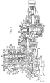
- Figure 1 is a sectional view of an embodiment of the present invention;
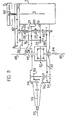
- Figure 2 is a schematic illustration of the apparatus of Figure 1; and
- figure 3 is a schematic illustration of another embodiment of the present invention.
- Referring to the drawings, numeral 1 designates an engine transversely provided in a vehicle at the front end thereof, a transmission 4 is disposed in alignment with a crankshaft 5 of the engine. A
main drive shaft 8 of the transmission 4 is rotatably supported by bearings 6 and 7 and is adapted to be coupled to the engine through aclutch 2. Theclutch 2 comprises, as well known, aflywheel 9 secured to the crankshaft 5, a diaphragm spring. 10, apressure plate 11, aclutch disc 12 having a facing .13, a release arm 14, and a release bearing 15. - A
sub-drive shaft 16 is disposed in parallel with themain drive shaft 8, supported by bearings 17 and 18.-Themain drive shaft 8 has agear 19 for the fourth speed, agear 20 for the third speed, agear 21 for the second speed and agear 22 for the first speed. On thesub-drive shaft 16, bears 23, 24, 25 and 26, respectively engaged withgears 19 to 22, are rotatably mounted. Between thegears synchromesh device 27 is provided for coupling thegear sub-drive shaft 16 for the fourth and third speeds..Asynchromesh device 28 is similarly provided between thegears gear 29, agear 31 provided on thesleeve 30 of thesynchromesh device 28 and anidler gear 32 are provided for the reverse drive. - In this apparatus, the output of the transmission is transmitted from an
output gear 35 secured to the inner end of thesub-drive shaft 16 to afinal reduction device 33 and to atransfer device 34. Theoutput gear 35 engages with afinal reduction gear 36 secured to adifferential case 38 of adifferential 37. The differential comprises ashaft 41,pinions 42 and side gears 43 (Fig. 2) each of which has anoutput shaft 44. Eachshaft 44 is connected to afront axle 45 through a joint. The differential is positioned at the inner side of the final reduction gear, so that the differential may be located in a central point of the tread of the vehicle. - The
final reduction gear 36 engages with agear 49 of thetransfer device 34. Thegear 49 is rotatably mounted on ashaft 48 transversely provided.and supported bybearings transfer device 34 comprises aclutch 50 which comprises aclutch hub 51 a engaged with theshaft 48 by splines, asleeve 51 slidably engaged with theclutch hub 51 a by splines, and splines 52 provided on the side ofgear 49. Thesleeve 51 is shifted by a shift lever (not shown) for engaging splines of the sleeve with the splines 52 thereby to couple thegear 49 to theshaft 48. Abevel gear 53 is secured to theshaft 48 at the end of the shaft and engages with thebevel gear 54 secured to adrive shaft 55 linked to acoaxial propeller shaft 57. which is longitudinally disposed along the center line of the vehicle. Theclutch 50 and a pair ofbevel gears gear 49,clutch 50 andbevel gear 54 are closely positioned relative to each other. - Therefore, the
drive shaft 55 andpropeller shaft 57 may be disposed along the center line of the vehicle. - In operation, the output of the engine 1 is transmitted to the
main drive shaft 8 of the transmission 4 through theclutch 2 and further to thesub-drive shaft 16 by the engagement of thesynchromesh device output gear 35 is transmitted to thefront axle 45 through thefinal reduction gear 36 anddifferential 37 and also to thetransfer gear 49. When thesleeve 51 of theclutch 50 is engaged with the splines 52 by manipulating the shift lever, the rotation of thegear 49 is transmitted to theshaft 48 through theclutch hub 51 a. Thus, the output of the transmission is transmitted to thedrive shaft 55 andpropeller shaft 57 through thebevel gears - Referring to Figure 3 showing another embodiment of the present invention, the transmission 4 is disposed in parallel to the engine 1. An
output shaft 60 of theclutch 2 is tubular and co-axial with the crankshaft 5 of the engine 1. A gear 61 secured to theshaft 60 engages with afear 62 rotatably mounted on themain drive shaft 8 of the transmission 4. Thegear 22 for the first speed is secured to thegear 62. Thegear 21 for the second speed,gear 20 for the third speed andgear 19 for the fourth speed are rotatably mounted on the shaft, respectively.Gears 23 to 26 respectively engaged withgears 19 to 22 are secured to thesub-drive shaft 16. Theoutput gear 35 is secured to themain drive shaft 8, which engages with thefinal reduction gear 36. Thedifferential 37 is secured to the inner. side of thefinal reduction gear 36 so that the differential is disposed at a central position of the vehicle. The construction of thetransfer device 34 and other devices is the same as in the first embodiment of Figures 1 and 2, and hence thepropeller shaft 57 is disposed along the center line of the vehicle. - The output of the engine 1 is transmitted to the sub-drive shaft through the
clutch 2,shaft 60,gears 61, 62 andgears 22 to 26. The output at theoutput gear 35 is transmitted to thefront axle 45 through thefinal reduction gear 36 anddifferential 37 and also selectively to the rear axle through thetransfer device 34,clutch 50,bevel gears propeller shaft 57. - In accordance with the present invention, the transfer device for the four-wheel drive is disposed adjacent the differential for the two- wheel drive, which is disposed at a central position of the vehicle. Accordingly, the propeller shaft for the four-wheel drive is disposed along the center line of the vehicle.
Claims (2)
Applications Claiming Priority (2)
| Application Number | Priority Date | Filing Date | Title |
|---|---|---|---|
| JP15462479A JPS5679024A (en) | 1979-11-29 | 1979-11-29 | Power transmission unit for four wheel drive car |
| JP154624/79 | 1979-11-29 |
Publications (4)
| Publication Number | Publication Date |
|---|---|
| EP0030120A2 EP0030120A2 (en) | 1981-06-10 |
| EP0030120A3 EP0030120A3 (en) | 1982-03-24 |
| EP0030120B1 true EP0030120B1 (en) | 1985-01-02 |
| EP0030120B2 EP0030120B2 (en) | 1991-04-03 |
Family
ID=15588244
Family Applications (1)
| Application Number | Title | Priority Date | Filing Date |
|---|---|---|---|
| EP80304241A Expired EP0030120B2 (en) | 1979-11-29 | 1980-11-26 | Transmission apparatus for four-wheel drive motor vehicle |
Country Status (6)
| Country | Link |
|---|---|
| US (1) | US4422520A (en) |
| EP (1) | EP0030120B2 (en) |
| JP (1) | JPS5679024A (en) |
| DE (1) | DE3044712C2 (en) |
| GB (1) | GB2064449B (en) |
| NL (1) | NL185910C (en) |
Families Citing this family (29)
| Publication number | Priority date | Publication date | Assignee | Title |
|---|---|---|---|---|
| IT1203316B (en) * | 1979-12-17 | 1989-02-15 | Sirp Spa | GROUP AND PROCEDURE FOR THE TRANSFORMATION OF A CHANGE OF SPEED FOR VEHICLES AND CHANGE OF SPEED OBTAINED THROUGH SUCH TRANSFORMATION |
| JPS56154328A (en) | 1980-04-25 | 1981-11-28 | Nissan Motor Co Ltd | Four-wheel-drive vehicle |
| JPS56154329A (en) | 1980-04-25 | 1981-11-28 | Nissan Motor Co Ltd | Four-wheel-drive vehicle |
| JPS5766021A (en) * | 1980-10-09 | 1982-04-22 | Fuji Heavy Ind Ltd | Horizontally-land four-wheel driving trans-axle |
| JPS57118927A (en) | 1981-01-09 | 1982-07-24 | Nissan Motor Co Ltd | Four-wheel drive car |
| JPS57118928A (en) | 1981-01-09 | 1982-07-24 | Nissan Motor Co Ltd | Four-wheel drive car |
| JPS57126727A (en) * | 1981-01-29 | 1982-08-06 | Mazda Motor Corp | Driving apparatus capable of 4-wheel driving |
| JPS57182527A (en) * | 1981-04-30 | 1982-11-10 | Nissan Motor Co Ltd | 4-wheel-drive vehicle |
| JPS57186522A (en) * | 1981-05-11 | 1982-11-17 | Nissan Motor Co Ltd | 4-wheel driven car |
| JPS5812830A (en) * | 1981-07-15 | 1983-01-25 | Nissan Motor Co Ltd | Four wheel driven vehicle |
| JPS5830834A (en) * | 1981-08-20 | 1983-02-23 | Nissan Motor Co Ltd | Four-wheel driven car |
| US4476952A (en) * | 1981-11-25 | 1984-10-16 | Nissan Motor Company, Limited | Four-wheel vehicle drive system |
| JPS58211922A (en) * | 1982-06-04 | 1983-12-09 | Honda Motor Co Ltd | Front and rear wheel drive |
| IT1154009B (en) * | 1982-06-11 | 1987-01-21 | Silvio Sala | DIFFERENTIAL GROUP COUPLER OF TORQUE BETWEEN THE FRONT AND REAR AXLES OF A MOTOR VEHICLE |
| JPS59130738A (en) * | 1983-01-18 | 1984-07-27 | Honda Motor Co Ltd | Transmission gear |
| AU551271B2 (en) * | 1983-01-18 | 1986-04-24 | Honda Giken Kogyo Kabushiki Kaisha | Four wheel drive |
| FR2562000B1 (en) * | 1984-03-28 | 1989-01-06 | Dangel Henry | TWO DIFFERENTIAL TRANSMISSION DEVICE FOR A FOUR-DRIVE VEHICLE |
| IT1184935B (en) * | 1984-03-29 | 1987-10-28 | Mitsubishi Electric Corp | SYSTEM TO DETECT THREE-DIMENSIONAL COORDINATES WITH THE USE OF A PROCESSOR |
| GB2158020B (en) * | 1984-04-14 | 1987-12-23 | Honda Motor Co Ltd | Four-wheel drive system for vehicle |
| JPS6190629U (en) * | 1984-11-20 | 1986-06-12 | ||
| JPS6194429U (en) * | 1984-11-28 | 1986-06-18 | ||
| DE3607373A1 (en) * | 1986-03-06 | 1987-09-10 | Porsche Ag | 4WD DRIVE FOR A MOTOR VEHICLE |
| IT1187985B (en) * | 1986-04-15 | 1987-12-23 | Amsea Spa | TRANSMISSION GROUP FOR VEHICLES |
| JPH0194127U (en) * | 1987-12-16 | 1989-06-21 | ||
| DE58903690D1 (en) * | 1988-04-20 | 1993-04-15 | Haag Ag Streit | DEVICE FOR EXAMINING AND TREATING THE EYE. |
| EP0451028B1 (en) * | 1990-03-31 | 1996-02-14 | Suzuki Motor Corporation | Power train for four wheel drive vehicle |
| FR2670722B1 (en) * | 1990-12-19 | 1995-03-24 | Peugeot | TRANSFER DEVICE CONNECTING A MOTOR-PROPELLER UNIT BEFORE A MOTOR VEHICLE TO A LONGITUDINAL TRANSMISSION SHAFT THEREOF. |
| FR2703635B1 (en) * | 1993-04-05 | 1995-07-07 | Dangel Henry | MOTOR VEHICLE WITH FOUR DRIVE WHEELS. |
| JP2006117075A (en) * | 2004-10-20 | 2006-05-11 | Toyota Motor Corp | Power transmission device for vehicle and power transmission device for four-wheel drive vehicle |
Family Cites Families (14)
| Publication number | Priority date | Publication date | Assignee | Title |
|---|---|---|---|---|
| US2705539A (en) * | 1948-11-01 | 1955-04-05 | James V Martin | Motor vehicle |
| DE801249C (en) * | 1949-04-07 | 1950-12-28 | Heinrich Lanz Akt Ges | Four-wheel drive, especially for agricultural tractors |
| GB887849A (en) * | 1959-09-22 | 1962-01-24 | Morris Motors Ltd | Improvements relating to power transmissions for motor vehicles |
| DE1655918A1 (en) * | 1966-11-05 | 1970-01-08 | Zahnradfabrik Friedrichshafen | Gearboxes for motor vehicles |
| US3451574A (en) * | 1967-02-20 | 1969-06-24 | Ernst Weichel | Load carrying vehicle having driving engine located with a portion extending into the loading space |
| US3580350A (en) * | 1969-01-23 | 1971-05-25 | Gen Motors Corp | Vehicle power unit and drive train |
| US3740766A (en) * | 1972-01-24 | 1973-06-26 | E Kobylarz | Golf gloves |
| US3848691A (en) * | 1972-11-30 | 1974-11-19 | Chrysler Corp | Full time four wheel drive |
| SE417628B (en) * | 1973-05-22 | 1981-03-30 | United Turbine Ab & Co | FOR A WHEEL VEHICLE DEDICATED GAS TRUBIN |
| JPS51151452A (en) * | 1975-06-20 | 1976-12-25 | Mitsubishi Motors Corp | Cha nge gear |
| JPS5383119U (en) * | 1976-12-11 | 1978-07-10 | ||
| JPS5433434A (en) * | 1977-08-18 | 1979-03-12 | Nozawa Seisakusho Kk | Total wheel drive type wagon |
| GB1591956A (en) * | 1977-09-22 | 1981-07-01 | Toyota Motor Co Ltd | Driving apparatus for automotive vehicles |
| JPS5449723A (en) * | 1977-09-26 | 1979-04-19 | Toyota Motor Corp | Drive gear for cars |
-
1979
- 1979-11-29 JP JP15462479A patent/JPS5679024A/en active Granted
-
1980
- 1980-11-26 GB GB8037875A patent/GB2064449B/en not_active Expired
- 1980-11-26 EP EP80304241A patent/EP0030120B2/en not_active Expired
- 1980-11-27 DE DE3044712A patent/DE3044712C2/en not_active Expired
- 1980-11-28 NL NLAANVRAGE8006494,A patent/NL185910C/en not_active IP Right Cessation
- 1980-11-28 US US06/210,873 patent/US4422520A/en not_active Expired - Lifetime
Also Published As
| Publication number | Publication date |
|---|---|
| GB2064449A (en) | 1981-06-17 |
| US4422520A (en) | 1983-12-27 |
| GB2064449B (en) | 1984-05-31 |
| DE3044712A1 (en) | 1981-08-27 |
| JPS6243884B2 (en) | 1987-09-17 |
| NL185910C (en) | 1990-08-16 |
| EP0030120B2 (en) | 1991-04-03 |
| JPS5679024A (en) | 1981-06-29 |
| EP0030120A3 (en) | 1982-03-24 |
| NL185910B (en) | 1990-03-16 |
| DE3044712C2 (en) | 1985-07-04 |
| EP0030120A2 (en) | 1981-06-10 |
| NL8006494A (en) | 1981-07-01 |
Similar Documents
| Publication | Publication Date | Title |
|---|---|---|
| EP0030120B2 (en) | Transmission apparatus for four-wheel drive motor vehicle | |
| US4476953A (en) | Four-wheel vehicle drive system | |
| EP0072990B1 (en) | Four-wheel vehicle drive system | |
| US4476952A (en) | Four-wheel vehicle drive system | |
| US4431079A (en) | Four-wheel vehicle drive system | |
| CA1140363A (en) | Slip axle drive mechanism | |
| US4441575A (en) | Four-wheel vehicle drive system | |
| US4645029A (en) | Four-wheel vehicle drive system | |
| US4459874A (en) | Transaxle mechanism of four-wheel vehicle drive system | |
| EP1231095A2 (en) | Power on demand differential | |
| GB1583655A (en) | Transfer case for automotive vehicles | |
| US5042610A (en) | Four-wheel drive vehicle | |
| US4907672A (en) | Transmission for a four-wheel drive motor vehicle | |
| US4399717A (en) | Change-speed transmission for wheeled vehicles | |
| US4635504A (en) | Transmission systems for motor vehicles with four-wheel drive | |
| US4699237A (en) | Four-wheel drive system for motor vehicles | |
| EP0096904B1 (en) | Differential assembly for distribution of torque between the front and rear axles of an automotive vehicle | |
| US4915191A (en) | Transfer device for a four-wheel drive vehicle | |
| GB2126178A (en) | Four-wheel-drive for motor vehicles | |
| EP0273877B1 (en) | Permanent four-wheel-drive transmission for a vehicle with a transverse engine | |
| JPH0798460B2 (en) | Power transmission device for four-wheel drive vehicle | |
| JPH0341943Y2 (en) | ||
| SU1585180A1 (en) | Vehicle transmission | |
| JP2638886B2 (en) | Center differential with auxiliary transmission | |
| JPH0343051Y2 (en) |
Legal Events
| Date | Code | Title | Description |
|---|---|---|---|
| PUAI | Public reference made under article 153(3) epc to a published international application that has entered the european phase |
Free format text: ORIGINAL CODE: 0009012 |
|
| AK | Designated contracting states |
Designated state(s): CH FR IT SE |
|
| ITCL | It: translation for ep claims filed |
Representative=s name: STUDIO BIANCHETTI |
|
| PUAL | Search report despatched |
Free format text: ORIGINAL CODE: 0009013 |
|
| AK | Designated contracting states |
Designated state(s): CH FR IT SE |
|
| 17P | Request for examination filed |
Effective date: 19820921 |
|
| ITF | It: translation for a ep patent filed | ||
| GRAA | (expected) grant |
Free format text: ORIGINAL CODE: 0009210 |
|
| AK | Designated contracting states |
Designated state(s): CH FR IT LI SE |
|
| ET | Fr: translation filed | ||
| PLBI | Opposition filed |
Free format text: ORIGINAL CODE: 0009260 |
|
| 26 | Opposition filed |
Opponent name: STEYR- DAIMLER- PUCH AKTIENGESELLSCHAFT Effective date: 19851002 |
|
| PUAH | Patent maintained in amended form |
Free format text: ORIGINAL CODE: 0009272 |
|
| STAA | Information on the status of an ep patent application or granted ep patent |
Free format text: STATUS: PATENT MAINTAINED AS AMENDED |
|
| 27A | Patent maintained in amended form |
Effective date: 19910403 |
|
| AK | Designated contracting states |
Kind code of ref document: B2 Designated state(s): CH FR IT LI SE |
|
| ITF | It: translation for a ep patent filed | ||
| ET3 | Fr: translation filed ** decision concerning opposition | ||
| REG | Reference to a national code |
Ref country code: CH Ref legal event code: AEN |
|
| ITTA | It: last paid annual fee | ||
| PGFP | Annual fee paid to national office [announced via postgrant information from national office to epo] |
Ref country code: FR Payment date: 19921027 Year of fee payment: 13 |
|
| PGFP | Annual fee paid to national office [announced via postgrant information from national office to epo] |
Ref country code: CH Payment date: 19921029 Year of fee payment: 13 |
|
| PGFP | Annual fee paid to national office [announced via postgrant information from national office to epo] |
Ref country code: SE Payment date: 19921103 Year of fee payment: 13 |
|
| PG25 | Lapsed in a contracting state [announced via postgrant information from national office to epo] |
Ref country code: SE Effective date: 19931127 |
|
| PG25 | Lapsed in a contracting state [announced via postgrant information from national office to epo] |
Ref country code: LI Effective date: 19931130 Ref country code: CH Effective date: 19931130 |
|
| PG25 | Lapsed in a contracting state [announced via postgrant information from national office to epo] |
Ref country code: FR Effective date: 19940729 |
|
| REG | Reference to a national code |
Ref country code: CH Ref legal event code: PL |
|
| REG | Reference to a national code |
Ref country code: FR Ref legal event code: ST |
|
| EUG | Se: european patent has lapsed |
Ref document number: 80304241.5 Effective date: 19940610 |
|
| APAC | Appeal dossier modified |
Free format text: ORIGINAL CODE: EPIDOS NOAPO |
|
| APAC | Appeal dossier modified |
Free format text: ORIGINAL CODE: EPIDOS NOAPO |
|
| APAH | Appeal reference modified |
Free format text: ORIGINAL CODE: EPIDOSCREFNO |