EP0029757B1 - Agencement d'un support de colonne de direction et d'un support de pédales sur un véhicule automobile - Google Patents
Agencement d'un support de colonne de direction et d'un support de pédales sur un véhicule automobile Download PDFInfo
- Publication number
- EP0029757B1 EP0029757B1 EP80401469A EP80401469A EP0029757B1 EP 0029757 B1 EP0029757 B1 EP 0029757B1 EP 80401469 A EP80401469 A EP 80401469A EP 80401469 A EP80401469 A EP 80401469A EP 0029757 B1 EP0029757 B1 EP 0029757B1
- Authority
- EP
- European Patent Office
- Prior art keywords
- support
- supports
- arrangement
- steering column
- pedal
- Prior art date
- Legal status (The legal status is an assumption and is not a legal conclusion. Google has not performed a legal analysis and makes no representation as to the accuracy of the status listed.)
- Expired
Links
- 238000010008 shearing Methods 0.000 claims 2
- 238000000926 separation method Methods 0.000 description 2
- 239000000470 constituent Substances 0.000 description 1
- 230000006378 damage Effects 0.000 description 1
- 238000006073 displacement reaction Methods 0.000 description 1
- 210000000056 organ Anatomy 0.000 description 1
Images
Classifications
-
- G—PHYSICS
- G05—CONTROLLING; REGULATING
- G05G—CONTROL DEVICES OR SYSTEMS INSOFAR AS CHARACTERISED BY MECHANICAL FEATURES ONLY
- G05G1/00—Controlling members, e.g. knobs or handles; Assemblies or arrangements thereof; Indicating position of controlling members
- G05G1/30—Controlling members actuated by foot
- G05G1/32—Controlling members actuated by foot with means to prevent injury
-
- B—PERFORMING OPERATIONS; TRANSPORTING
- B62—LAND VEHICLES FOR TRAVELLING OTHERWISE THAN ON RAILS
- B62D—MOTOR VEHICLES; TRAILERS
- B62D1/00—Steering controls, i.e. means for initiating a change of direction of the vehicle
- B62D1/02—Steering controls, i.e. means for initiating a change of direction of the vehicle vehicle-mounted
- B62D1/16—Steering columns
- B62D1/18—Steering columns yieldable or adjustable, e.g. tiltable
- B62D1/19—Steering columns yieldable or adjustable, e.g. tiltable incorporating energy-absorbing arrangements, e.g. by being yieldable or collapsible
Definitions
- the present invention relates to the arrangement, in a motor vehicle, of a steering column support and a pedal support.
- the steering column and the pedals being necessarily placed facing the driver of a vehicle, their respective supports are located at the same vertical plane, longitudinal with respect to the vehicle.
- the column support is usually fixed under a transverse awning box, while the pedal support is fixed on an apron which forms a separation between the passenger compartment and the engine compartment.
- it is common to join the two supports together by a rigid connection.
- the object of the invention is to remedy this drawback.
- the invention therefore relates to the arrangement of a steering column support and a pedal support on a motor vehicle, the column support being fixed under a transverse awning box, the pedal support being fixed on a apron and the two supports being interconnected (according to the brochure "Peugeot 304" of September 1969, page 65).
- This arrangement is characterized in that the constituent parts of the pedal support are offset transversely and longitudinally with respect to the column support, the connection between the two supports being produced by a retractable element under the action of a predetermined force.
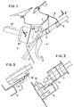
- an awning box 1 arranged transversely between a windshield 2 and an apron 3.
- the latter constitutes a separation between a passenger compartment 4 and an engine compartment 5.
- a support 6 carrying a steering column 7 by means of collars 8.
- a support 9 carrying an axis 10 on which are articulated clutch 11 and brake 12 pedals.
- the support 9 for pedals also carries, in a known manner, an amplifier 13 for braking force and a brake master cylinder 14 arranged in the engine compartment 5.
- the support 9 for pedals and the support 6 for the column are connected by a rigid plate 15.
- This plate 15 is, for example, welded to the support 6 and fixed to the support 9 by fixing members such as rivets 16 having limited shear strength. (This plate 15 could naturally be welded to the support 9 and fixed by rivets on the support 6).
- connection between the plate 15 and the support 9 is carried out on a part of the latter which is offset transversely relative to the support 6 of the column.
- the connecting element between the supports 6 and 9 is constituted by a plate 17 welded to the support 9 and fixed by bolts 18 to the support 6.
- it is the deformation of the plate 17 itself even, under the action of a predetermined force, which allows the movement of the support 9 towards the interior of the passenger compartment 4, without driving the support 6, therefore without recoil of the steering wheel.
Landscapes
- Engineering & Computer Science (AREA)
- Physics & Mathematics (AREA)
- General Physics & Mathematics (AREA)
- Automation & Control Theory (AREA)
- Chemical & Material Sciences (AREA)
- Combustion & Propulsion (AREA)
- Transportation (AREA)
- Mechanical Engineering (AREA)
- Body Structure For Vehicles (AREA)
- Steering Controls (AREA)
Description
- La présente invention se rapporte à l'agencement, dans un véhicule automobile, d'un support de colonne de direction et d'un support de pédales.
- La colonne de direction et les pédales étant nécessairement placées face au conducteur d'un véhicule, leurs supports respectifs se trouvent au droit d'un même plan vertical, longitudinal par rapport au véhicule.
- Le support de colonne est habituellement fixé sous un caisson transversal d'auvent, tandis que le support de pédales est fixé sur un tablier qui forme séparation entre l'habitacle et le compartiment du moteur. De plus, pour assurer une bonne résistance de l'ensemble, il est courant de réunir les deux supports entre eux par une liaison rigide.
- Or, on trouve fréquemment dans le compartiment moteur des organes mécaniques, tels que le maître cylindre et l'assistance de freinage, qui sont portés par le support de pédales et qui, en cas de choc par l'avant, tendent à repousser le support de pédales vers l'intérieur de l'habitacle (voir la brochure "Peugeot 304" de septembre 1969, page 65). Ce déplacement est transmis au support de colonne de direction et, par conséquent, à l'ensemble colonne-volant, ce qui peut occasionner des lésions particulièrement graves pour le conducteur.
- Le but de l'invention est de remédier à cet inconvénient.
- L'invention concerne donc l'agencement d'un support de colonne de direction et d'un support de pédales sur un véhicule automobile, le support de colonne étant fixé sous un caisson transversal d'auvent, le support de pédales étant fixé sur un tablier et les deux supports étant reliés entre eux (selon la brochure "Peugeot 304" de septembre 1969, page 65).
- Cet agencement est caractérisé en ce que les parties constitutives du support de pédales sont décalées transversalement et longitudinalement par rapport au support de colonne, la liaison entre les deux supports étant réalisée par un élément escamotable sous l'action d'un effort prédéterminé.
- Deux exemples de réalisation font l'objet de la description qui suit, en référence aux dessins joints dans lesquels:
- - la Fig. 1 est une vue latérale d'un agencement selon l'invention;
- - la Fig. 2 est une coupe suivant la ligne 2-2 de la Fig. 1;
- - la Fig. 3 est une vue identique à celle de la Fig. 2, pour une variante de réalisation.
- On a représenté, sur la Fig. 1, un caisson d'auvent 1, disposé transversalement entre un parebrise 2 et un tablier 3. Ce dernier constitue une séparation entre un habitacle 4 et un compartiment moteur 5.
- Sous le caisson d'auvent 1 est fixé un support 6 portant une colonne de direction 7 au moyen de colliers 8. Sur le tablier 3, du côté de l'habitacle 4, est fixé un support 9 portant un axe 10 sur lequel sont articulées des pédales d'embrayage 11 et de frein 12.
- Le support 9 de pédales port également, de façon connue, un amplificateur 13 de force de freinage et un maître cylindre de frein 14 disposés dans le compartiment moteur 5.
- Comme on le voit sur la Fig. 2, le support 9 de pédales et le support 6 de colonne sont reliés par une plaque rigide 15. Cette plaque 15 est, par exemple, soudée sur le support 6 et fixée sur le support 9 par des organes de fixation tels que des rivets 16 présentant une résistance limitée au cisaillement. (Cette plaque 15 pourrait naturellement être soudée sur le support 9 et fixée par des rivets sur le support 6).
- La liaison entre la plaque 15 et le support 9 est réalisée sur une partie de ce dernier qui se trouve décalée transversalement par rapport au support 6 de colonne.
- Grâce à cette disposition, si le partie avant du véhicule se trouve écrasée au cours d'un choc et que des organes mécaniques situés dans le compartiment moteur repoussent, par l'intermédiaire du maître cylindre 14, le support 9 de pédales, il se produit une rupture des rivets 16 et le support 9 se déplace sans repousser le support 6 de colonne, donc sans qu'il y ait recul du volant de direction.
- Dans la variante représentée à la Fig. 3, l'élément de liaison entre les supports 6 et 9 est constitué par une plaque 17 soudée sur le support 9 et fixée par des boulons 18 sur le support 6. Dans cet exemple, c'est la déformation de la plaque 17 elle-même, sous l'action d'un effort prédéterminé, qui permet le déplacement du support 9 vers l'intérieur de l'habitacle 4, sans entraînement du support 6, donc sans recul du volant de direction.
Claims (4)
Applications Claiming Priority (2)
| Application Number | Priority Date | Filing Date | Title |
|---|---|---|---|
| FR7929136 | 1979-11-27 | ||
| FR7929136A FR2470411A1 (fr) | 1979-11-27 | 1979-11-27 | Agencement d'un support de colonne de direction et d'un support de pedales sur un vehicule automobile |
Publications (2)
| Publication Number | Publication Date |
|---|---|
| EP0029757A1 EP0029757A1 (fr) | 1981-06-03 |
| EP0029757B1 true EP0029757B1 (fr) | 1983-04-13 |
Family
ID=9232117
Family Applications (1)
| Application Number | Title | Priority Date | Filing Date |
|---|---|---|---|
| EP80401469A Expired EP0029757B1 (fr) | 1979-11-27 | 1980-10-15 | Agencement d'un support de colonne de direction et d'un support de pédales sur un véhicule automobile |
Country Status (3)
| Country | Link |
|---|---|
| EP (1) | EP0029757B1 (fr) |
| DE (1) | DE3062772D1 (fr) |
| FR (1) | FR2470411A1 (fr) |
Families Citing this family (5)
| Publication number | Priority date | Publication date | Assignee | Title |
|---|---|---|---|---|
| JPH08216Y2 (ja) * | 1988-07-25 | 1996-01-10 | 日産自動車株式会社 | エネルギー吸収式ステアリングコラム |
| DE19522398C1 (de) * | 1995-06-23 | 1996-12-19 | Daimler Benz Ag | Sicherheitsanordnung im Fußraum eines Kraftwagens |
| JP3488387B2 (ja) * | 1998-10-30 | 2004-01-19 | 富士機工株式会社 | ステアリングコラム保持構造 |
| GB201109306D0 (en) | 2011-06-03 | 2011-07-20 | Agco Int Gmbh | Steering and brake arrangement |
| ES2673283T3 (es) * | 2014-06-19 | 2018-06-21 | Iveco S.P.A. | Lugar de conducción de un vehículo comercial |
Family Cites Families (10)
| Publication number | Priority date | Publication date | Assignee | Title |
|---|---|---|---|---|
| DE7113766U (de) * | 1971-04-08 | 1971-08-12 | Opel A Ag | Pedalanordnung mit durch Stoß lösbarer Befestigung an der Stirnwand in Kraftfahrzeugen |
| DE2222397A1 (de) * | 1972-05-06 | 1973-11-22 | Volkswagenwerk Ag | Anordnung fuer ein mit einer steuersaeule und zumindest einem pedal ausgeruestetes geraet, insbesondere kraftfahrzeug |
| US3827710A (en) * | 1973-06-25 | 1974-08-06 | Gen Motors Corp | Vehicle steering column installation |
| GB1460027A (en) * | 1973-10-08 | 1976-12-31 | Chrysler Uk | Motor vehicles process for producing 3,5-cyclic adenylic acid |
| DE2363895A1 (de) * | 1973-12-21 | 1975-07-03 | Daimler Benz Ag | Sicherheitslenkung fuer kraftwagen |
| JPS51143225A (en) * | 1975-06-02 | 1976-12-09 | Fuji Kiko Co Ltd | Shock energy absorbing steering column |
| JPS5218638A (en) * | 1975-08-05 | 1977-02-12 | Fuji Kiko Co Ltd | Shock-absorbing steering system for autmobile |
| JPS5294636U (fr) * | 1976-01-13 | 1977-07-15 | ||
| US4117741A (en) * | 1976-12-01 | 1978-10-03 | Honda Giken Kogyo Kabushiki Kaisha | Collapsible steering column |
| JPS5946826B2 (ja) * | 1977-04-06 | 1984-11-15 | 光洋精工株式会社 | エネルギ吸収機能を持つステアリングコラム支持装置 |
-
1979
- 1979-11-27 FR FR7929136A patent/FR2470411A1/fr active Granted
-
1980
- 1980-10-15 DE DE8080401469T patent/DE3062772D1/de not_active Expired
- 1980-10-15 EP EP80401469A patent/EP0029757B1/fr not_active Expired
Non-Patent Citations (1)
| Title |
|---|
| La brochure "Peugeot 304" de septembre 1969, p. 65. * |
Also Published As
| Publication number | Publication date |
|---|---|
| FR2470411A1 (fr) | 1981-05-29 |
| EP0029757A1 (fr) | 1981-06-03 |
| DE3062772D1 (en) | 1983-05-19 |
| FR2470411B1 (fr) | 1984-09-07 |
Similar Documents
| Publication | Publication Date | Title |
|---|---|---|
| US6595079B2 (en) | Collapsible steering column assembly for a vehicle | |
| EP0794103B1 (fr) | Dispositif antirotation de corps de colonne de direction de véhicule automobile | |
| FR2489772A1 (fr) | Panneau de compensation aerodynamique pour vehicule | |
| EP0647787A1 (fr) | Biellette de reprise de couple pour moteur de véhicule | |
| US5947223A (en) | Restraint for a drive assembly of a motor vehicle | |
| JP2002302087A (ja) | 小型車両のエンジン支持構造 | |
| GB1571129A (en) | Motorized three wheeled vehicle | |
| EP0965506B1 (fr) | Dispositif de montage d'une pédale d'un véhicule automobile | |
| GB2230493A (en) | Reducing collision damage in vehicles | |
| EP0029757A1 (fr) | Agencement d'un support de colonne de direction et d'un support de pédales sur un véhicule automobile | |
| FR2750093A1 (fr) | Dispositif d'escamotage d'un pedalier de vehicule automobile | |
| EP1035004A1 (fr) | Agencement d'une colonne de direction dans un habitacle de véhicule automobile et véhicule correspondant | |
| FR2537529A1 (fr) | Direction pour vehicule automobile, avec colonne de direction et support deformables | |
| FR2491854A1 (fr) | Colonne de direction telescopable pour vehicules automobiles | |
| FR2526388A1 (fr) | Timonerie de direction de vehicule automobile, notamment voiture de tourisme comportant un essieu a roues directrices | |
| EP0989007A1 (fr) | Dispositif formant renfort et porte pour véhicule automobile | |
| FR2740882A1 (fr) | Agencement perfectionne de supports de colonne de direction et de pedales dans un vehicule automobile | |
| FR2596010A1 (fr) | Train arriere a micro-braquage actif pour vehicule automobile | |
| EP0985593B1 (fr) | Chassis de véhicule automobile | |
| FR2980435A1 (fr) | Systeme de protection pour une barre de renvoi transversale d'un systeme de freinage | |
| US4667761A (en) | Caliper body supporting structure for disk brakes in vehicles having two rear wheels | |
| FR2883245A1 (fr) | Dispositif de liaison entre un support de colonne de direction et un element de structure, traverse et vehicule automobile associe. | |
| WO1995021083A1 (fr) | Servomoteur d'assistance de freinage, a securite accrue | |
| FR2748441A1 (fr) | Structure de support pour poste de conduite de vehicule automobile | |
| FR2870199A1 (fr) | Agencement pour roue de secours de vehicule automobile |
Legal Events
| Date | Code | Title | Description |
|---|---|---|---|
| PUAI | Public reference made under article 153(3) epc to a published international application that has entered the european phase |
Free format text: ORIGINAL CODE: 0009012 |
|
| 17P | Request for examination filed |
Effective date: 19810210 |
|
| AK | Designated contracting states |
Designated state(s): DE GB IT |
|
| ITF | It: translation for a ep patent filed | ||
| GRAA | (expected) grant |
Free format text: ORIGINAL CODE: 0009210 |
|
| AK | Designated contracting states |
Designated state(s): DE GB IT |
|
| REF | Corresponds to: |
Ref document number: 3062772 Country of ref document: DE Date of ref document: 19830519 |
|
| PGFP | Annual fee paid to national office [announced via postgrant information from national office to epo] |
Ref country code: DE Payment date: 19830922 Year of fee payment: 4 |
|
| RAP2 | Party data changed (patent owner data changed or rights of a patent transferred) |
Owner name: AUTOMOBILES CITROEN Owner name: AUTOMOBILES PEUGEOT |
|
| GBPC | Gb: european patent ceased through non-payment of renewal fee | ||
| PG25 | Lapsed in a contracting state [announced via postgrant information from national office to epo] |
Ref country code: DE Effective date: 19850702 |
|
| PG25 | Lapsed in a contracting state [announced via postgrant information from national office to epo] |
Ref country code: GB Effective date: 19881118 |
|
| PLBE | No opposition filed within time limit |
Free format text: ORIGINAL CODE: 0009261 |
|
| STAA | Information on the status of an ep patent application or granted ep patent |
Free format text: STATUS: NO OPPOSITION FILED WITHIN TIME LIMIT |