EP0029569B1 - Method and device for correcting spatial distortion in a scintillation camera - Google Patents
Method and device for correcting spatial distortion in a scintillation camera Download PDFInfo
- Publication number
- EP0029569B1 EP0029569B1 EP80107129A EP80107129A EP0029569B1 EP 0029569 B1 EP0029569 B1 EP 0029569B1 EP 80107129 A EP80107129 A EP 80107129A EP 80107129 A EP80107129 A EP 80107129A EP 0029569 B1 EP0029569 B1 EP 0029569B1
- Authority
- EP
- European Patent Office
- Prior art keywords
- energy
- correction
- signal
- image element
- amplifier
- Prior art date
- Legal status (The legal status is an assumption and is not a legal conclusion. Google has not performed a legal analysis and makes no representation as to the accuracy of the status listed.)
- Expired
Links
Images
Classifications
-
- G—PHYSICS
- G01—MEASURING; TESTING
- G01T—MEASUREMENT OF NUCLEAR OR X-RADIATION
- G01T1/00—Measuring X-radiation, gamma radiation, corpuscular radiation, or cosmic radiation
- G01T1/16—Measuring radiation intensity
- G01T1/161—Applications in the field of nuclear medicine, e.g. in vivo counting
- G01T1/164—Scintigraphy
- G01T1/1641—Static instruments for imaging the distribution of radioactivity in one or two dimensions using one or several scintillating elements; Radio-isotope cameras
- G01T1/1642—Static instruments for imaging the distribution of radioactivity in one or two dimensions using one or several scintillating elements; Radio-isotope cameras using a scintillation crystal and position sensing photodetector arrays, e.g. ANGER cameras
Definitions
- the invention relates to a method and an apparatus for correcting the spatial distortion of a scintillation camera that generates image event position coordinate signals and image event energy signals Z c , correction factors in response to image events having a predetermined reference energy level Z REF during an off-line calibration phase are determined and stored, and image event position coordinate signals corrected in accordance with the stored correction factors are generated in an on-line examination phase.
- a method and a device of this type are e.g. B. known from US-PS 37 45 345.
- the respective correction factor which corresponds to a picture event position coordinate signal, is read out and, in accordance with this, the picture event energy signal is finally corrected directly for each picture event.
- the corrected image event energy signals are finally fed to an energy analyzer which has an energy window with a defined width. If a corrected image event energy signal falls within the limits of the window of the energy analyzer, it is accepted as a valid image event and forwarded to the image recording device for recording. However, if the image event energy signal lies outside the limits of the energy window, the energy analyzer considers the image event to be invalid; it is rejected and therefore does not appear.
- the Lapidus article describes a method for modifying the Z (energy) signal of an image event by reading out a stored correction factor (from a 64 x 64 data field) corresponding to the position of the image event.
- the correction factor changes the pulse width of the Z signal with the aid of a pulse width modulator.
- the image device uses this Z signal with a variable pulse width to vary the intensity of the image point imaged on a film. A flowing fashion is used to “learn” the distribution of the non-uniformity. A data field of values is thus obtained and stored, which represents the response of the camera detector to each of the 4096 X, Y positions.
- the object of the present invention is therefore to further develop a method and a device specifically for correcting the spatial distortion in such a way that an even more precise correction is possible, it being in particular of no importance how many individual energy sources with different energy levels a camera images or how many energy levels a single energy source contains.
- An apparatus for performing this method includes a scintillation camera that generates image event position coordinate signals and image event energy signals Z c and that includes a spatial distortion corrector that also generates image event position coordinate signals that are corrected in accordance with stored spatial distortion correction factors, wherein the Correction factors during an off-line calibration phase in response to image events that have a preselected reference energy level Z REF have been determined and stored.
- this device is characterized in that the correction device has a signal change unit for measuring the dependence of the spatial distortion of the scintillation camera on different energy levels of the image events, which differ from the reference energy level Z REF of the off-line calibration phase, and for forming a spatial distortion pattern from the measured dependency of spatial distortion, which takes into account the spatial degree of distortion that increases with decreasing energy level, and that the signal changing unit, depending on the spatial distortion pattern formed, modifies the correction of the image event position coordinate signals such that energy level-corrected image event position coordinate signals result for each image event, provided the associated image event Energy signal Z c has a different energy level compared to the reference energy level Z REF .
- the present invention thus enables a dynamic change in the spatial distortion correction of the scintillation camera with the aid of the signal change unit of the correction device.
- the correction device contains a memory in which the correction factors for the spatial distortion are stored in a predetermined addressable format.
- the correction device converts the individual image event position coordinate signals into the corrected image event position coordinate signals in accordance with the stored correction factors.
- a combining unit enables the already corrected image event position coordinate signals to be changed in accordance with the respective energy level of the image event, so that an accurate correction of the spatial distortion is also obtained for the current energy level of the image event. In this way, the scintillation camera is automatically and dynamically capable of correcting spatial distortion effects in image events with different energy levels.
- Different energy levels of the image events occur when the scintillation camera captures radiation from a radiation source that has a variety of different energy levels, or when it images a plurality of energy sources, each of which has an energy level that differs from the energy level for which the stored ones Correction factors for the spatial distortion had been calculated.
- the change unit changes the correction of the spatial distortion without having to change previously saved correction factors or even having to change the scintillation camera itself by internal modification.
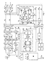
- An on-line correction device for correcting the spatial distortion which is used to practice the method according to the invention, has the reference number 11 in FIG. 1. It is shown in connection with parts of the scintillation camera.
- the scintillation camera of Figure 1 is of the general type that converts scintillation events into electrical signals that represent the location coordinates of each of the scintillation events and their energy. This type is e.g. B. also known as “Anger type”.
- Such scintillation cameras are described, for example, in US Patents 3011 057, 3745345 and 3984689, to which express reference is made for the purpose of extracting further information regarding the structure and functioning of a scintillation camera.
- Scintillation events always occur when e.g. B. gamma rays hit a scintillation crystal on the end face of the camera. They can be detected by means of photomultiplier tubes (one of which is indicated in FIG. 1, for example, with the reference number 12), for which purpose these are arranged behind the scintillation crystal in a predetermined configuration pattern, so that the light energy of each scintillation event can be converted into electrical pulses.
- photomultiplier tubes one of which is indicated in FIG. 1, for example, with the reference number 12
- Normal scintillation cameras work with groups of about 37 to 75 photomultiplier tubes so as to be able to capture the scintillation events across the surface of the scintillation crystal, as shown, for example, in Figures 1 and 2 of the aforementioned U.S. Patent 3745345.
- the pulse outputs of all photomultiplier tubes 12 within the tube arrangement are connected to sample and hold stages 24 via the preamplifier 14, summing and subtracting amplifier J6, integration stages 18, sample and hold stages 20 and multiplier stages 22, which, as in FIG 1 is shown in principle, at its outputs 26, 28 provide the X and Y position coordinates of each scintillation event.
- the output signal of each photomultiplier tube in the tube assembly depends on the proximity of the affected photomultiplier tube to the scintillation event.
- the output signals of the photomultiplier tubes 12 are also fed to an energy analysis circuit 30 for the Z signal.
- the circuit 30 includes a summing amplifier stage 32, an integration stage 34 and two sample and hold stages 36 and 38.
- the output of the sample and hold stage 38 generates at 40 an uncorrected Z signal Z IN which represents the energy of each image event, such as it arises, represents.
- the circuit 30 for the Z signal also includes a processing circuit 42 which is connected to the outputs of the summing amplifier 32 and the integrator 34 and which generates an output signal at 44 for the sample and hold stage 36 and for an equalization and control stage 46 .
- the processing circuit 42 supplies the device with the function of a coarse analyzer on the input side, as it is e.g. B. in US Pat. No.
- the output of the equalization and control stage 46 goes on the one hand to the sample and hold stage 38 and on the other hand to an energy analyzer 48 which has an energy window with a certain width.
- the X and Y coordinate signals at 26 and 28 and the Z energy signal Z IN at 40 are input signals to the energy correction device 10.
- the on-line energy correction device 10 comprises an analog-digital converter 50 which is connected to the outputs 26 and 28 for the X and Y position coordinate signals.
- the analog-to-digital converter 50 provides the outputs 52 with the X and Y position coordinates for each picture event as a digital value on a suitable number of digital control lines.
- the digital output values are given to the addressing input of an energy correction factor memory 54.
- the memory 54 has a data field of energy correction factors stored therein, which are arranged within the data field in such a way that they can be addressed in accordance with information about the coordinates of image field positions, which information represents parts of the area or image carrier of the image field of the camera.
- the energy correction factors are determined in an off-line calibration phase and stored in the energy correction factor memory 54 for the purpose of use during the on-line examination phase of the scintillation camera and the associated apparatus.
- each image event arising from a position X, Y calls via the associated digitized X and Y coordinate signals in the energy cor rectification factor memory 54 an address for a memory cell in which an energy correction factor is stored, which is specifically assigned to the image event from the position X, Y for its energy correction.
- the energy correction value is then read out from the memory.
- the energy correction factor memory 54 in response to each picture event, provides an output signal at 56 on a predetermined number of digital control lines and in a digital format that represents the energy correction factor to suitably match the energy signal at 40 that is also from the picture event originates, in accordance with the pixel at which the event occurred in the image area can be supplied to carry out the correction.
- the digital correction factor which is denoted by f (p) in FIG. 1, is output from the output 56 of the energy correction factor memory 54 to the input of an energy signal correction unit 58 of the energy correction device 10.
- the Z signal Z IN of 40 is also fed as an input signal to the correction unit 58.
- the energy signal correction unit 58 then delivers an corrected energy signal Z c in analog form at an output 60.
- the corrected energy signal Z c at 60 is fed to the input of the energy analyzer 48.
- the energy analyzer 48 now compares the energy level of the corrected energy signal Z c at 60 for each image event with a preselected energy window which is defined by lower and upper energy limits. As a result of the comparison, the analyzer 48 generates an acceptance signal at the output 62 when the corrected energy signal Z c lies within the limits of the preselected energy window. Accordingly, however, it delivers a rejection signal at the output 62 if the energy signal is outside the limits of the energy window.
- the output 62 of the energy analyzer 48 is connected to a light key control stage 64, which controls the associated image display and analysis device via the light key output 66.
- light key control stage 64 determines whether or not an image event should be displayed or possibly counted for analytical purposes.
- the position coordinates of the event to be displayed are derived from the X, Y position coordinate signals at 26, 28. It ultimately determines the correct position of the image event in the image matrix, which is produced by the associated image display and analysis device.
- the output 26 for the X position coordinate signal is connected to a sample and hold stage 70. This generates a signal X a for a first input of an X mixing and spectrum gate 72.
- the output 28 for the Y position coordinate signal is connected to a sample and hold stage 71 which generates a signal Y a which corresponds to the first Input of a Y-mixing and spectrum gate 74 is fed.
- the outputs of the mixing and spectrum gates 72 and 74 are each connected to one of two orientation gates 76 and 78.
- the outputs of the gates 76 and 78 directly control the vertical and horizontal deflection, via which the position of the image event to be displayed is finally determined in the image of the image device or on the analysis device.
- the X-mixing and spectrum gate 72 also has a second input, which is connected to a first output ⁇ X of the correction device 11 for correcting the spatial distortion.
- the Y-mixing and spectrum gate 74 is located with a second input at a second output ⁇ Y of the correction device 11.
- a third input for each of the two gates 72 and 74 is also with the output 83 of a control stage 81 for a spectrum display connected, which is controlled on the one hand by the output signal of the energy analyzer 48 and on the other hand by the corrected energy signal Z c .
- the energy signal correction unit 58 corrects the uncorrected Z energy signal at 40 in accordance with a correction factor f (p) so as to minimize the non-uniformity of the energy response of the scintillation camera as a function of the position of the image event on the camera image area .
- the energy signal correction unit 58 then supplies a corrected energy signal Z c at 60 to the energy analyzer 48, which finally decides whether the image event is accepted for display or whether it is rejected.
- the correction can also be carried out in connection with a single radiation source which itself has a plurality of different energy levels. However, the correction is also possible if the image events originate from a plurality of sources which have different energy levels of the radiation from one another.
- the type of correction remains the same; it is only necessary to provide a correspondingly higher number of energy analyzers with correspondingly different energy windows for evaluating several energy levels. This possibility is indicated in FIG. 1 by adding two further energy analyzers 90 and 92.
- the correction device 11 contains a correction factor memory 108, in which correction factors for correcting the spatial distortion are stored in the form of a predetermined addressable data field.
- the correction factors serve to correct the distortion of image events in the course of the on-line examination phase.
- the correction factors that are stored in the memory 108 were determined in an off-line calibration phase preceding the on-line examination phase.
- this off-line calibration phase the spatial distortion characteristics of the scintillation camera, based on a special reference Energy level, exactly determined.
- the off-line testing, measuring and analyzing apparatus used is not shown in detail. However, it is of a type as described in EP-A-00 21 366 and z. B is shown as a data storage device 14 and computer 16 in FIG. 1 of this application.
- the individual correction factors can of course also be determined in other known ways, for. B. according to one of the methods used in the prior art described above.
- the image area of the scintillation camera is divided into a matrix of 64 horizontal and 64 vertical lines.
- the associated correction factor for the spatial distortion is then determined for the corner points of each surface element of this matrix.
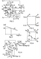
- FIG. 3 shows the correction factors in the form of vectors which indicate the direction of correction. These vectors each attack at the corner points of the individual screen elements of the 64 x 64 matrix. Each vector at a cross point of the matrix is composed of an X correction component and a Y correction component of the correction factor assigned to this cross point.
- the correction factor can therefore be referred to as AV (X, Y) in the following.
- each vector indicates the direction of the correction.
- the respective vector is directed in the opposite direction to that which was measured in the off-line calibration phase as a measure of the spatial distortion.
- the respective vector of the illustration in FIG. 3 thus defines a correction factor which counteracts the measured distortion at the respective point of attack.
- the correction vector therefore places the pixel that was previously incorrectly positioned due to the spatial distortion into the correct position.
- the four correction factor vectors V1, V2, V3, V4 in FIG. 3 thus represent the correction factors in four adjacent points (X i , Y j ), (X i +1, Y i ), (X i , Y i +1), (X i + 1 , Y i + 1) of the 64 x 64 data field.
- the data field is stored in the memory 108 of the correction device 11 for the spatial distortion as a number of coefficients C 1 to C 8 , the sums and differences of the current X and Contain Y-correction factor components of the data field, as they were determined by the off-line test, measurement and analysis apparatus.
- each coefficient C 1 to C 8 is composed of eight bits of information.
- the correction device 11 for the spatial distortion contains an analog-digital converter (ADC) 100 for the X coordinate and an analog-digital converter (ADC) 102 for the Y coordinate .
- the ADC 100 converts the X a position coordinate signal supplied to its analog input into two data streams X u and X L.
- the ADC 102 converts the position coordinate signal Y a supplied to its analog input into two separate data streams Y u and Y L.
- the indices U of the data streams X u and Y u characterize the resulting data in the order of “most significant data x.
- the indices L of X L and Y identify data that are classified as «least significant data».
- the most significant data X u , Y u are fed to the X and Y addressing inputs of the correction factor memory 108 via data lines 104 and 106, respectively.
- the correction factor memory 108 then supplies the coefficients C 1 to C 8 in digital form on a data line 110.
- the data line 110 is connected to the digital data input of a correction interpolator 112.
- This correction interpolator 112 also includes two further data inputs with data lines 114 and 116.
- the least significant data X L are fed to the interpolator via the data line 114.
- the least significant data Y L are fed to the interpolator via line 116.
- These least significant data X L and Y L on the data lines 114 and 116 define the residual functions R x and Ry, as shown in FIG. 4 ′.
- the signal change unit 13 for changing the correction of the spatial distortion now generates an energy change signal ZVR for the correction interpolator 112.
- the stored coefficients C 1 to C 8 of the correction factors are modified in accordance with the level of the energy signal Z c .
- the energy signal Z c arrives on the output line 63 of the sample and hold stage 61 to the signal change unit 13 of the correction device 11.
- correction interpolator 112 is designed in such a way that it carries out the interpolation operations recorded below and converts the results ⁇ X, ⁇ Y into an analog signal form:
- R x and Ry represent the coordinates of the image event within a cell of the data field.
- the correction factors AX and AY which are obtained according to the above operations, are applied to the gates 72 and 74 as corresponding AX and AY analog signals.
- the X a , Y a position coordinate signals of each image event, as supplied by the scintillation camera, are thus corrected by the factors AX and ⁇ Y.
- Energy-level-corrected position coordinate signals X c , Y c are thus obtained. These are corrected for spatial distortion in accordance with the coefficients C 1 to C 8 of the memory 108 depending on the change in the stored coefficients.
- Such a change is carried out by the signal ZVR in the case of a picture event if there is a difference between the energy level of the picture event and that energy level on the basis of which the correction factors in the off-line calibration phase were calculated. The change is directly dependent on the difference between the energy level of the picture event and the last-mentioned energy level.
- the spatial distortion is greater for image events with lower energy levels than for those with higher energy levels.
- This can be done by using two different radioactive sources, e.g. B. Americium 241, which has an energy level of 80 keV, and Barium 133, which has an energy level of 360 keV. If one compares the uncorrected images of both sources, the image of Americium 241 shows increased intensities or so-called "hot spots in the tube center of the photomultiplier tubes, while the image of Barium 133 shows lower intensities or so-called” cold spots "at these points. Americium 241 therefore causes the greater spatial distortion in comparison with barium 133. The amount of distortion thus changes inversely with the level of the energy level of the picture event.
- the signal changing unit 13 corrects a correction factor in inversely proportional to the energy level of the image event when such correction is necessary. As already mentioned before, this correction is always necessary if the energy level of the respective image event is different from that of the reference energy level Z REF . for which the correction factors had been calculated in the off-line calibration phase.
- the signal change unit 13 is used as it is e.g. B. is shown in Figure 5, for changing correction factors, a relationship between the change signal ZVR and the energy of the energy signal Z c in the sense that with linearly decreasing Z c, the change signal ZVR increases linearly (linear opposite relationship).
- the change unit 13 therefore generates a change signal ZVR specifically assigned to it for each image event in response to the energy level which specifically has this event.
- the correction factors measured and stored during the off-line phase are automatically and dynamically adapted to changed conditions from picture event to picture event.
- the correction of the spatial distortion is thus also carried out automatically and dynamically in the right way.
- the scintillation camera therefore always maps any type of energy source from which the image events originate without distortion.
- This source can be a single source that has a plurality of different energy levels; however, the camera can also image a plurality of sources that have different energy levels.
- the linearly opposing relationship between the image event energy signal Z c and the energy change signal ZVR of the change unit 13 in the embodiment according to FIG. 5 is shown in the diagram in FIG.
- the reference energy level Z REF is plotted on the abscissa, for which the correction factors were measured during the off-line calibration phase.
- the reference energy level is, for example, 122 keV.
- the signal change unit 13 for changing the correction of the spatial distortion comprises a voltage source with the reference voltage VR, which is on the one hand at ground reference potential 122 and on the other hand at one end of a potentiometer 124, which has the resistance value R2.
- the other end of the potentiometer 124 leads to a switch 126 (S1) which can be switched between two switch positions A and B. In switch position A, the switch connects the second end of potentiometer 124 to ground reference potential 122.
- the potentiometer 124 develops a partial voltage at the potentiometer tap, which is set in position A of the switch S1 so that it assumes the value KVR.
- the partial voltage KVR is fed to the non-inverting input of an amplifier stage 128, which generates the change signal ZVR on the output side.
- the output of amplifier 128 is fed back to the inverting input.
- the reference voltage VR is also connected to the inverting input of an amplifier 132 via an ohmic resistor 130 with the resistance value R.
- the non-inverting input of the amplifier 132 is connected to ground reference potential.
- the output of amplifier 132 is fed back to the inverting input via an ohmic resistor 134, which also has a resistance value of R.
- amplifier 132 thus works as an inverting amplifier with gain one.
- the amplifier accordingly supplies the voltage VR on the output side.
- This output voltage is coupled via an adjustable resistor 136 with the resistance value R4 to the inverting input of an amplifier 138.
- an ohmic resistor 140 which has the resistance value R ; also has the picture event energy signal Z c of 63.
- the non-inverting input of the amplifier 138 again has ground reference potential 122.
- An adjustable feedback resistor 142 with the resistance value R f is connected between the output of the amplifier 138 and the inverting input.
- the settings as discussed are all made with switch S1 in position A.
- the output of the amplifier 138 leads to the switch contact B of the switch 126.
- the resistance value R, of the resistor 142 can be set so that, in accordance with the relationship between Z c and ZVR obtained by measurement and analysis required gain factor K1 according to Figure 7 results.
- the change signal ZVR at the output of the amplifier stage 128 results as follows:
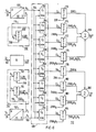
- the correction factor memory 108 contains a total of eight electronically programmable read-only memories 150 to 164, which are called EPROM in common use and in which the coefficients C 1 to C 8 of the correction factors are stored.
- the division between the individual EPROMs is such that the four EPROMs 150, 152, 154, 156 provide the X correction factors C i , C 2 , C 3 and C 4 , while the EPROMs 158, 160, 162 and 164 for the output of the Y correction factors C s to C 8 are responsible. All EPROMs 150 to 164 are addressed by the most significant data bits of the information X u and Y u on lines 104 and 106.
- EPROM's 150 to 164 can store up to 4000 data words, each data word comprising a total of eight bits of information.
- the 64 x 64 matrix of the data field has a total of 4096 picture elements; As already mentioned at the beginning, however, the image area of the camera is circular. For this reason there is always a certain number of picture elements of the square 64 x 64 matrix outside the circle of the camera picture area, so that a 4 K memory (memory content 4 kilobits) is sufficient to store the information actually required.
- each EPROM 150 to 164 is now assigned an 8-bit multiplier digital-to-analog converter 170 to 184 in the interpolator 112, hereinafter referred to as MDAC for short.
- MDAC multiplier digital-to-analog converter
- the connection of each EPROM with the MDAC assigned to it is such that that at the output of an EPROM Correction factor C 1 to C 8 is applied to the digital input of the MDAC.
- the multiplier inputs are the interpolation information shown in FIG.
- the change information ZVR is supplied by the signal change unit 13.
- the change information ZVRR x comes from an MDAC 190 of the interpolator 112, on the digital input of which the least significant bits of the information X L are given via the line 114. As already mentioned, these input data are designated R x .
- the information ZVR is fed to the multiplier input by the change unit 13.
- the remaining information ZVRRy and ZVRR xR y are accordingly provided by two further MDACs 192 and 194 of the interpolator 112. Both MDAC's are fed at the digital input via line 116 with the least significant information of the signal Y in the form of Ry.
- the signal ZVR is again present at the multiplier input of the MDAC 192.
- the output signal ZVRR X of the MDAC 190 is present at the multiplier input of the MDAC 194.
Description
Die Erfindung bezieht sich auf ein Verfahren und ein Gerät zur Korrektur der räumlichen Verzerrung einer Szintillationskamera, die Bildereignis-Positionskoordinatensignale und Bildereignis-Energiesignale Zc erzeugt, wobei während einer off-line Eichphase Korrekturfaktoren in Antwort auf Bildereignisse mit einem vorgegebenen Referenz-Energieniveau ZREF ermittelt und abgespeichert werden und wobei in einer on-line Untersuchungsphase entsprechend den abgespeicherten Korrekturfaktoren korrigierte Bildereignis-Positionskoordinatensignale erzeugt werden.The invention relates to a method and an apparatus for correcting the spatial distortion of a scintillation camera that generates image event position coordinate signals and image event energy signals Z c , correction factors in response to image events having a predetermined reference energy level Z REF during an off-line calibration phase are determined and stored, and image event position coordinate signals corrected in accordance with the stored correction factors are generated in an on-line examination phase.
Ein Verfahren und ein Gerät dieser Art sind z. B. durch die US-PS 37 45 345 vorbekannt.A method and a device of this type are e.g. B. known from US-PS 37 45 345.
Bei Szintillationskameras, z. B. solchen des « Anger-Typs •, ist es wichtig, die ihnen innewohnende räumliche Verzerrung zu korrigieren, weil eine örtliche Verdichtung oder auch Expansion von Bilddaten der Bildereignisse vermieden werden muß. Eine örtliche Verdichtung oder Expansion der Bilddaten führt zu Schwankungen in der Bildintensität, die das Bild insgesamt verfälschen. Räumliche Verzerrungen sind das Ergebnis von systembedingten Fehlern in der Positionierung der Szintillationsereignisse, die sich aufgrund von Ungenauigkeiten und Nichtlinearitäten in den Ausgangsdaten über die Bildereignis-Positionskoordinaten des Anzeigegerätes ergeben. Die Charakteristik der räumlichen Verzerrung variiert in Abhängigkeit von der Position, in der ein Bildereignis auftritt, auf der Bildfläche der Kamera, so daß die Bildereignisse nicht an ihrem korrekten Ort im Gesamtbild abgebildet werden. Die räumliche Versetzung einzelner Ereignisse ist zwar im Bild nicht direkt visuell wahrnehmbar; sie führt aber dennoch zu Ungleichförmigkeiten im Bildfeld, die dann als Intensitätsänderungen merklich sichtbar sind.In scintillation cameras, e.g. B. of the "Anger type", it is important to correct the inherent spatial distortion, because a local compression or expansion of image data of the image events must be avoided. A local compression or expansion of the image data leads to fluctuations in the image intensity, which falsify the image as a whole. Spatial distortions are the result of system-related errors in the positioning of the scintillation events, which result from inaccuracies and non-linearities in the output data via the image event position coordinates of the display device. The characteristic of the spatial distortion varies depending on the position in which an image event occurs on the image surface of the camera, so that the image events are not reproduced in their correct location in the overall image. The spatial displacement of individual events is not directly visually perceptible in the picture; however, it still leads to irregularities in the image field, which are then noticeably visible as changes in intensity.
Weitere Verfahren zur Korrektur der räumlichen Verzerrung im Sinne einer Linearisierung sowie die zugehörigen Geräte wurden z. B. in der EP-A-00 21 366, veröffentlicht am 07.01.81, vorgeschlagen oder sie sind durch die folgenden Aufsätze bekannt :
- « Removal Of Gamma Camera Non-Linearity And Non-Uniformities Through Real-Time Signal Processing von G. F. Knoll et al., präsentiert im Juli 1979 in Paris auf der Konferenz für Nuklearmedizin,
- « On-Line Digital Methods For Correction Of Spatial And Energy Dependent Distortion Of Anger Camera lmages von Shabason et al. aus « A Review Of Information Processing In Medical Imaging •, Fifth International Conference, Seiten 376-388, Vanderbilt University, Nashville, Tenn. vom 27. Juni bis 1. Juli 1977,
- « Quantitative Studies With The Gamma Camera ; Correction For Spatial And Energy Distortion » von Soussaline et al. aus « A Review Of Information Processing In Medical Imaging ", Fifth International Conference, Seiten 360-375, Vanderbilt University, Nashville, Tenn. vom 27. Juni bis 1. Juli 1977.
- «Removal Of Gamma Camera Non-Linearity And Non-Uniformities Through Real-Time Signal Processing by GF Knoll et al., Presented in July 1979 in Paris at the conference for nuclear medicine,
- "On-Line Digital Methods For Correction Of Spatial And Energy Dependent Distortion Of Anger Camera lmages by Shabason et al. from “A Review Of Information Processing In Medical Imaging •, Fifth International Conference, pages 376-388, Vanderbilt University, Nashville, Tenn. from June 27 to July 1, 1977,
- «Quantitative Studies With The Gamma Camera; Correction For Spatial And Energy Distortion »by Soussaline et al. from "A Review Of Information Processing In Medical Imaging " , Fifth International Conference, pages 360-375, Vanderbilt University, Nashville, Tenn. from June 27 to July 1, 1977.
Die in diesem Stand der Technik beschriebenen Verfahren und Geräte arbeiten zufriedenstellend, solange die Bildereignisse auch tatsächlich Energieniveaus haben, die mit denen übereinstimmen, für die in der off-line Phase die Korrekturfaktoren zur Korrektur der räumlichen Verzerrung errechnet wurden. Problematisch wird es jedoch, wenn die Energieniveaus der Bildereignisse unterschiedlich sind zu jenen, für die die Korrekturfaktoren errechnet wurden. In diesem Falle, wo also die Charakteristik der räumlichen Verzerrung sich in Abhängigkeit vom Energieniveau des jeweiligen Bildereignisses ändert, ist ein Einsatz der Verfahren und der Geräte des Standes der Technik kaum mehr möglich. Dies gilt einerseits für jenen Fall, bei dem die Szintillationskamera eine Energiequelle abbildet, die für sich unterschiedliche Energienivaus hat. Es gilt andererseits aber auch für den Fall, daß bei einer Abbildung mit der Szintillationskamera mehrere Energiequellen eingesetzt werden, die unter sich unterschiedliche Energieniveaus haben. In beiden Fällen geht es um Energieniveaus, die Werte haben, die unterschiedlich sind zu jenen, für die die Korrekturfaktoren für die räumliche Verzerrung vorher errechnet wurden.The methods and devices described in this prior art work satisfactorily as long as the image events actually have energy levels that correspond to those for which the correction factors for correcting the spatial distortion were calculated in the off-line phase. However, it becomes problematic when the energy levels of the image events are different from those for which the correction factors have been calculated. In this case, where the characteristic of the spatial distortion changes depending on the energy level of the respective image event, the methods and devices of the prior art can hardly be used. On the one hand, this applies to the case in which the scintillation camera depicts an energy source that has different energy levels in itself. On the other hand, however, it also applies to the case that multiple energy sources are used in an image with the scintillation camera, which have different energy levels among themselves. In both cases, it is about energy levels that have values that are different from those for which the correction factors for the spatial distortion were previously calculated.
Es gibt im Zusammenhang mit Szintillationskameras auch noch weitere Korrekturverfahren und zugehörige Korrekturgeräte. Diese befassen sich aber alle mit der Korrektur von Ungleichförmigkeiten in der Energieverteilung bei Szintillationskameras. Die Ungleichförmigkeiten in der Energieverteilung stellen neben den Bildverfälschungen, die aufgrund der räumlichen Verzerrung auftreten, eine weitere Fehlerquelle für die Bildaufzeichnung dar. Ein Verfahren und ein Gerät zur Korrektur speziell der Ungleichförmigkeiten in der Energieverteilung sind bereits vorgeschlagen worden. Dem Vorschlag gemäß erfolgt die Korrektur anhand von Korrekturfaktoren, die in Form einer Matrix gespeichert sind und die während einer off-line Eichphase als Energieantwort der Szintillationskamera auf eine Feldflußquelle gemessen werden. Während der on-line Untersuchungsphase wird der jeweilige Korrekturfaktor, der mit einem Bildereignis-Positionskoordinatensignal korrespondiert, ausgelesen und in Übereinstimmung mit diesem schließlich das Bildereignis-Energiesignal für jedes Bildereignis direkt korrigiert. Die korrigierten Bildereignis-Energiesignale werden schließlich einem Energie-Analysator zugeleitet, der ein Energiefenster mit festgelegter Breite aufweist. Fällt ein korrigiertes Bildereignis-Energiesignal in die Grenzen des Fensters des Energie-Analysators, so wird es von diesem als gültiges Bildereignis akzeptiert und zur Aufzeichnung an das Bildaufzeichnungsgerät weitergeleitet. Liegt das Bildereignis-Energiesignal hingegen außerhalb der Grenzen des Energiefensters, so betrachtet der Energie-Analysator das Bildereignis für ungültig ; es wird von ihm abgelehnt und gelangt somit also nicht zur Anzeige.There are also other correction methods and associated correction devices in connection with scintillation cameras. However, these are all concerned with the correction of non-uniformities in the energy distribution in scintillation cameras. In addition to the image distortions that occur due to the spatial distortion, the non-uniformities in the energy distribution represent a further source of error for the image recording. A method and a device for correcting the non-uniformities in the energy distribution in particular have already been proposed. According to the proposal, the correction takes place on the basis of correction factors which are stored in the form of a matrix and which are measured during an off-line calibration phase as the energy response of the scintillation camera to a field flow source. During the on-line examination phase, the respective correction factor, which corresponds to a picture event position coordinate signal, is read out and, in accordance with this, the picture event energy signal is finally corrected directly for each picture event. The corrected image event energy signals are finally fed to an energy analyzer which has an energy window with a defined width. If a corrected image event energy signal falls within the limits of the window of the energy analyzer, it is accepted as a valid image event and forwarded to the image recording device for recording. However, if the image event energy signal lies outside the limits of the energy window, the energy analyzer considers the image event to be invalid; it is rejected and therefore does not appear.
Ein weiteres Verfahren sowie ein Gerät zur Korrektur der Ungleichförmigkeit der Energieverteilung ist aus dem Artikel « A New Method Of Correcting For Detector Non-Uniformity In Gamma Cameras " von Lapidus, Raytheon Medical Electronics, ST-3405, November 1977, bekannt.Another method and device for correcting the non-uniformity of the energy distribution is known from the article "A New Method Of Correcting For Detector Non-Uniformity In Gamma Cameras" by Lapidus, Raytheon Medical Electronics, ST-3405, November 1977.
Der Lapidus-Artikel beschreibt dabei ein Verfahren zum Modifizieren des Z (Energie)-Signals eines Bildereignisses dadurch, daß ein gespeicherter Korrekturfaktor (von einem 64 x 64 Datenfeld) entsprechend der Position des Bildereignisses ausgelesen wird. Der Korrekturfaktor verändert die Pulsbreite des Z-Signals unter Zuhilfenahme eines Pulsbreitenmodulators. Das Bildgerät benutzt dieses Z-Signal mit variabler Pulsbreite dazu, die Intensität des abgebildeten Bildpunktes auf einem Film zu variieren. Ein fließender Mode wird eingesetzt, um die Verteilung der Ungleichförmigkeit zu « erlernen •. Es wird so also ein Datenfeld von Werten erhalten und gespeichert, das die Antwort des Kameradetektors auf jede der insgesamt 4096 X, Y-Positionen repräsentiert.The Lapidus article describes a method for modifying the Z (energy) signal of an image event by reading out a stored correction factor (from a 64 x 64 data field) corresponding to the position of the image event. The correction factor changes the pulse width of the Z signal with the aid of a pulse width modulator. The image device uses this Z signal with a variable pulse width to vary the intensity of the image point imaged on a film. A flowing fashion is used to “learn” the distribution of the non-uniformity. A data field of values is thus obtained and stored, which represents the response of the camera detector to each of the 4096 X, Y positions.
Wie schon erläutert, beschäftigen sich die zuvor genannten Verfahren und Systeme aber nur mit der Korrektur der Ungleichförmigkeit der Energieverteilung. Sie bieten keine Lösung an, die es ermöglicht, jene Probleme zu bewältigen, die zuvor im Zusammenhang mit der Korrektur der räumlichen Verzerrung geschildert wurden.As already explained, the previously mentioned methods and systems only deal with the correction of the non-uniformity of the energy distribution. They do not offer a solution to deal with the problems previously described in connection with the correction of spatial distortion.
Aufgabe vorliegender Erfindung ist es also, ein Verfahren und ein Gerät speziell für die Korrektur der räumlichen Verzerrung dahingehend weiterzubilden, daß eine noch exaktere Korrektur möglich ist, wobei es insbesondere auch ohne Bedeutung sein soll, wieviele einzelne Energiequellen mit untereinander unterschiedlichen Energieniveaus eine Kamera abbildet oder wieviele Energieniveaus eine einzelne Energiequelle beinhaltet.The object of the present invention is therefore to further develop a method and a device specifically for correcting the spatial distortion in such a way that an even more precise correction is possible, it being in particular of no importance how many individual energy sources with different energy levels a camera images or how many energy levels a single energy source contains.
Die Aufgabe wird mit einem Verfahren der eingangs genannten Art erfindungsgemäß dadurch gelöst, daß es folgende Schritte in der on-line Untersuchungsphase umfaßt :
- a) es wird die Abhängigkeit der räumlichen Verzerrung der Szintillationskamera von verschiedenen, sich vom Referenz-Energieniveaus ZREF der off-line Eichphase unterscheidenden Energieniveaus der Bildereignisse gemessen ;
- b) aus der gemessenen Abhängigkeit der räumlichen Verzerrung wird ein räumliches Verzerrungsmuster gebildet, das den mit abnehmendem Energieniveau zunehmenden Verzerrungsgrad berücksichtigt ; und
- c) in Abhängigkeit von dem gebildeten räumlichen Verzerrungsmuster wird danach die Korrektur der Bildereignis-Positionskoordinatensignale dahingehend modifiziert, daß bei jedem Bildereignis sich energieniveaukorrigierte Bildereignis-Positionskoordinatensignale ergeben, sofern das zugehörige Bildereignis-Energiesignal Zc im Vergleich zum Referenz-Energieniveau ZREF ein unterschiedliches Energieniveau hat.
- a) the dependence of the spatial distortion of the scintillation camera on different energy levels of the image events, which differ from the reference energy level Z REF of the off-line calibration phase, is measured;
- b) a spatial distortion pattern is formed from the measured dependence of the spatial distortion, which takes into account the degree of distortion increasing with decreasing energy level; and
- c) depending on the spatial distortion pattern formed, the correction of the image event position coordinate signals is then modified such that energy level corrected image event position coordinate signals result for each image event, provided the associated image event energy signal Z c has a different energy level compared to the reference energy level Z REF Has.
Ein Gerät zur Durchführung dieses Verfahrens umfaßt eine Szintillationskamera, die Bildereignis-Positionskoordinatensignale und Bildereignis-Energiesignale Zc erzeugt und die eine Korrigiereinrichtung für die räumliche Verzerrung umfaßt, die zudem in Übereinstimmung mit gespeicherten Korrekturfaktoren für die räumliche Verzerrung korrigierte Bildereignis-Positionskoordinatensignale erzeugt, wobei die Korrekturfaktoren während einer off-line Eichphase in Antwort auf Bildereignisse, die ein vorgewähltes Referenz-Energieniveau ZREF haben, ermittelt und abgespeichert wurden. Dieses Gerät ist erfindungsgemäß dadurch gekennzeichnet, daß die Korrigiereinrichtung eine Signaländerungseinheit zum Messen der Abhängigkeit der räumlichen Verzerrung der Szintillationskamera von verschiedenen, sich vom Referenz-Energieniveau ZREF der off-line Eichphase unterscheidenden Energieniveaus der Bildereignisse und zur Bildung eines räumlichen Verzerrungsmusters aus der gemessenen Abhängigkeit der räumlichen Verzerrung umfaßt, das den mit abnehmendem Energieniveau zunehmenden räumlichen Verzerrungsgrad berücksichtigt, und daß die Signaländerungseinheit in Abhängigkeit vom gebildeten räumlichen Verzerrungsmuster die Korrektur der Bildereignis-Positionskoordinatensignale dahingehend modifiziert, daß bei jedem Bildereignis sich energieniveaukorrigierte Bildereignis-Positionskoordinatensignale ergeben, sofern das zugehörige Bildereignis-Energiesignal Zc im Vergleich zum Referenz- Energieniveau ZREF ein unterschiedliches Energieniveau hat.An apparatus for performing this method includes a scintillation camera that generates image event position coordinate signals and image event energy signals Z c and that includes a spatial distortion corrector that also generates image event position coordinate signals that are corrected in accordance with stored spatial distortion correction factors, wherein the Correction factors during an off-line calibration phase in response to image events that have a preselected reference energy level Z REF have been determined and stored. According to the invention, this device is characterized in that the correction device has a signal change unit for measuring the dependence of the spatial distortion of the scintillation camera on different energy levels of the image events, which differ from the reference energy level Z REF of the off-line calibration phase, and for forming a spatial distortion pattern from the measured dependency of spatial distortion, which takes into account the spatial degree of distortion that increases with decreasing energy level, and that the signal changing unit, depending on the spatial distortion pattern formed, modifies the correction of the image event position coordinate signals such that energy level-corrected image event position coordinate signals result for each image event, provided the associated image event Energy signal Z c has a different energy level compared to the reference energy level Z REF .
Die vorliegende Erfindung ermöglicht also eine dynamische Änderung der räumlichen Verzerrungskorrektur der Szintillationskamera unter Zuhilfenahme der Signaländerungseinheit der Korrigiereinrichtung. Die Korrigiereinrichtung beinhaltet dabei einen Speicher, in dem die Korrekturfaktoren für die räumliche Verzerrung in einem vorbestimmten adressierbaren Format gespeichert sind. Während der on-line Untersuchungsphase der Szintillationskamera wandelt die Korrigiereinrichtung die einzelnen Bildereignis-Positionskoordinatensignale in Übereinstimmung mit den gespeicherten Korrekturfaktoren in die korrigierten Bildereignis-Positionskoordinatensignale um. Eine Kombiniereinheit ermöglicht eine Änderung der bereits korrigierten Bildereignis-Positionskoordinatensignale in Übereinstimmung mit dem jeweiligen Energieniveau des Bildereignisses, so daß eine genaue Korrektur der räumlichen Verzerrung auch für das gerade vorhandene Energieniveau des Bildereignisses erhalten wird. Die Szintillationskamera ist auf diese Weise automatisch und dynamisch dazu fähig, räumliche Verzerrungseffekte bei .Bildereignissen mit verschiedenen Energieniveaus zu korrigieren. Unterschiedliche Energieniveaus der Bildereignisse treten auf, wenn die Szintillationskamera die Strahlung einer Strahlungsquelle aufnimmt, die eine Vielzahl von unterschiedlichen Energieniveaus hat, oder wenn sie eine Mehrzahl von Energiequellen abbildet, von denen jede ein Energieniveau aufweist, das von jenem Energieniveau abweicht, für das die gespeicherten Korrekturfaktoren für die räumliche Verzerrung errechnet worden waren. Die Änderungseinheit ändert die Korrektur der räumlichen Verzerrung, ohne daß vorher bereits gespeicherte Korrekturfaktoren geändert werden müssen oder gar die Szintillationskamera selbst durch innere Modifikation geändert werden muß.The present invention thus enables a dynamic change in the spatial distortion correction of the scintillation camera with the aid of the signal change unit of the correction device. The correction device contains a memory in which the correction factors for the spatial distortion are stored in a predetermined addressable format. During the on-line examination phase of the scintillation camera, the correction device converts the individual image event position coordinate signals into the corrected image event position coordinate signals in accordance with the stored correction factors. A combining unit enables the already corrected image event position coordinate signals to be changed in accordance with the respective energy level of the image event, so that an accurate correction of the spatial distortion is also obtained for the current energy level of the image event. In this way, the scintillation camera is automatically and dynamically capable of correcting spatial distortion effects in image events with different energy levels. Different energy levels of the image events occur when the scintillation camera captures radiation from a radiation source that has a variety of different energy levels, or when it images a plurality of energy sources, each of which has an energy level that differs from the energy level for which the stored ones Correction factors for the spatial distortion had been calculated. The change unit changes the correction of the spatial distortion without having to change previously saved correction factors or even having to change the scintillation camera itself by internal modification.
Weiterbildungen der Erfindung sind in den Ansprüchen 3 bis 13 enthalten. Weitere Vorteile und Einzelheiten der Erfindung ergeben sich aus der nachfolgenden Beschreibung eines Ausführungsbeispiels anhand der Zeichnung und in Verbindung mit den abhängigen Ansprüchen.Further developments of the invention are contained in claims 3 to 13. Further advantages and details of the invention emerge from the following description of an exemplary embodiment with reference to the drawing and in conjunction with the dependent claims.
Es zeigen :
Figur 1 das Prinzipschaltbild einer Szintillationskamera mit einem Korrekturgerät gemäß der Erfindung,Figur 2 die Erfindung in detaillierterer Darstellung als Ausschnitt aus demPrinzipschaltbild der Figur 1,- Figuren 3, 4 Darstellungen der Diagramme von Korrekturfaktoren an vier benachbarten Matrixpunkten,
- Figur 5 die Einheit zur Änderung der Korrektur einer Verzerrung gemäß
den Figuren 1 und 2 in detaillierterer Darstellung, - Figur 6 eine Ausführungsform der
Schaltung von Figur 2 in detaillierter Darstellung, - Figur 7 eine Darstellung der Energiekurve gegenüber dem Energieänderungssignal ZVR.
- FIG. 1 shows the basic circuit diagram of a scintillation camera with a correction device according to the invention,
- FIG. 2 shows the invention in more detail as a section of the basic circuit diagram of FIG. 1,
- FIGS. 3, 4 representations of the diagrams of correction factors at four adjacent matrix points,
- 5 shows the unit for changing the correction of a distortion according to FIGS. 1 and 2 in a more detailed representation,
- FIG. 6 shows an embodiment of the circuit from FIG. 2 in a detailed illustration,
- FIG. 7 shows the energy curve versus the energy change signal ZVR.
Ein on-line Korrigiergerät zur Korrektur der räumlichen Verzerrung, das dazu benutzt wird, die vorliegende erfindungsgemäße Methode zu praktizieren, hat in der Figur 1 die Bezugsziffer 11. Es ist dargestellt in Verbindung mit Teilen der Szintillationskamera. Die Szintillationskamera der Figur 1 ist von dem allgemeinen Typ, der Szintillationsereignisse in elektrische Signale umwandelt, die die Ortskoordinaten jedes der Szintillationsereignisse und deren Energie repräsentieren. Dieser Typ ist z. B. auch als «Anger-Typ• gut bekannt. Solche Szintillationskameras sind beispielsweise in den US-Patenten 3011 057, 3745345 und 3984689 beschrieben, auf die zwecks Entnahme weiterer Information hinsichtlich Aufbau und Funktionsweise einer Szintillationskamera ausdrücklich Bezug genommen wird.An on-line correction device for correcting the spatial distortion, which is used to practice the method according to the invention, has the
Szintillationsereignisse treten grundsätzlich immer dann auf, wenn z. B. Gammastrahlen auf einen Szintillationskristall an der Stirnfläche der Kamera auftreffen. Sie lassen sich mittels Fotovervielfacherröhren (eine davon ist in der Figur 1 z. B. mit der Kennziffer 12 angedeutet) erfassen, wozu diese in einem vorbestimmten Konfigurationsmuster hinter dem Szintillationskristall angeordnet sind, um so die Lichtenergie jedes Szintillationsereignisses in elektrische Pulse umformen zu können. Es gibt besondere Ausgestaltungen von Szintillationskameras, bei denen zwischen dem Kristall und den Fotovervielfacherröhren auch noch eine Anordnung eines Lichtleiters vorhanden ist. Normale Szintillationskameras arbeiten mit Gruppen von etwa 37 bis 75 Fotovervielfacherröhren, um so die Szintillationsereignisse quer über die Oberfläche des Szintillationskristalls erfassen zu können, so wie es beispielsweise in den Figuren 1 und 2 des vorher erwähnten US-Patentes 3745345 dargestellt ist.Scintillation events always occur when e.g. B. gamma rays hit a scintillation crystal on the end face of the camera. They can be detected by means of photomultiplier tubes (one of which is indicated in FIG. 1, for example, with the reference number 12), for which purpose these are arranged behind the scintillation crystal in a predetermined configuration pattern, so that the light energy of each scintillation event can be converted into electrical pulses. There are special designs of scintillation cameras in which there is also an arrangement of a light guide between the crystal and the photomultiplier tubes. Normal scintillation cameras work with groups of about 37 to 75 photomultiplier tubes so as to be able to capture the scintillation events across the surface of the scintillation crystal, as shown, for example, in Figures 1 and 2 of the aforementioned U.S. Patent 3745345.
In Übereinstimmung mit üblicher Detektorelektronik von Szintillationskameras sind die Pulsausgänge aller Fotovervielfacherröhren 12 innerhalb der Röhrenanordnung über Vorverstärker 14, Summier- und SubtrahierverstärkerJ6, Integrationsstufen 18, Abtast- und Haltestufen 20 und Multiplizierstufen 22 mit Abtast- und Haltestufen 24 verbunden, die, so wie es in der Figur 1 grundsätzlich dargestellt ist, an ihren Ausgängen 26, 28 die X- und Y-Positionskoordinaten eines jeden Szintillationsereignisses liefern. Das Ausgangssignal einer jeden Fotovervielfacherröhre in der Röhrenanordnung hängt ab von der Nähe der betroffenen Fotovervielfacherröhre zum Szintillationsereignis.In accordance with conventional detector electronics of scintillation cameras, the pulse outputs of all
Die Ausgangssignale der Fotovervielfacherröhren 12 werden auch noch einem Energieanalysierkreis 30 für das Z-Signal zugeleitet. Der Kreis 30 umfaßt dabei eine Summierverstärkerstufe 32, eine Integrationsstufe 34 und zwei Abtast- und Haltestufen 36 und 38. Der Ausgang der Abtast- und Haltestufe 38 erzeugt bei 40 ein unkorrigiertes Z-Signal ZIN, das die Energie eines jeden Bildereignisses, so wie es anfällt, repräsentiert. Der Kreis 30 für das Z-Signal umfaßt aber auch noch einen Verarbeitungskreis 42, der an den Ausgängen des Summierverstärkers 32 und des Integrators 34 liegt und der bei 44 ein Ausgangssignal für die Abtast- und Haltestufe 36 sowie für eine Entzerr- und Steuerstufe 46 erzeugt. Der Verarbeitungskreis 42 versorgt das Gerät mit der Funktion eines eingangsseitigen Grobanalysators, so wie er z. B. in der US-Patentschrift 39 84 689 nach Aufbau und Funktionsweise beschrieben ist. Der Ausgang der Entzerr- und Steuerstufe 46 geht einerseits auf die Abtast- und Haltestufe 38 und andererseits auf einen Energie-Analysator 48, der ein Energiefenster mit bestimmter Breite aufweist. Die X- und Y-Koordinatensignale bei 26 und 28 und das Z-Energiesignal ZIN bei 40 liegen als Eingangssignale am Energiekorrekturapparat 10.The output signals of the
Das on-line Energiekorrigiergerät 10 umfaßt einen Analog-Digital-Konverter 50, der mit den Ausgängen 26 und 28 für die X- und Y-Positionskoordinatensignale verbunden ist. Der Analog-Digital-Konverter 50 liefert an den Ausgängen 52 die X- und Y-Positionskoordinate für jedes Bildereignis als Digitalwert auf einer geeigneten Anzahl von digitalen Steuerleitungen. Die digitalen Ausgangswerte werden auf den Adressiereingang eines Energiekorrekturfaktor-Speichers 54 gegeben. Der Speicher 54 hat in sich ein Datenfeld von Energiekorrigierfaktoren gespeichert, die innerhalb des Datenfeldes so angeordnet sind, daß sie in Einklang mit Informationen über die Koordinaten von Bildfeldpositionen adressierbar sind, welche Informationen Flächenteile oder Bildträger des Bildfeldes der Kamera repräsentieren. Die Energiekorrekturfaktoren werden in einer off-line Eichphase bestimmt und im Energiekorrekturfaktor-Speicher 54 gespeichert zum Zwecke der Benutzung während der on-line Untersuchungsphase der Szintillationskamera und des zugeordneten Apparates.The on-line energy correction device 10 comprises an analog-
Während der on-line Untersuchungsphase der Szintillationskamera ruft jedes aus einer Position X, Y anfallende Bildereignis über die zugehörigen digitalisierten X- und Y-Koordinatensignale im Energiekorrekturfaktor-Speicher 54 eine Adresse für eine Speicherzelle auf, in der ein Energiekorrekturfaktor gespeichert ist, der speziell dem Bildereignis aus der Position X, Y zu dessen Energiekorrektur zugeordnet ist. Der Energiekorrekturwert wird daraufhin vom Speicher ausgelesen. Der Energiekorrekturfaktor-Speicher 54 liefert demgemäß also in Antwort auf jedes Bildereignis ein Ausgangssignal bei 56 auf einer vorbestimmten Zahl von digitalen Steuerleitungen und in einem digitalen Format, das den Energiekorrekturfaktor so repräsentiert, daß er in geeigneter Weise dem Energiesignal bei 40, das ebenfalls vom Bildereignis stammt, in Übereinstimmung mit dem Bildpunkt, an dem das Ereignis in der Bildfläche aufgetreten ist, zur Durchführung der Korrektur zugeführt werden kann.During the on-line examination phase of the scintillation camera, each image event arising from a position X, Y calls via the associated digitized X and Y coordinate signals in the energy cor
Der digitale Korrekturfaktor, der in Figur 1 mit f(p) bezeichnet ist, wird dazu vom Ausgang 56 des Energiekorrekturfaktor-Speichers 54 auf den Eingang einer Energiesignal-Korrektureinheit 58 des Energiekorrigiergerätes 10 gegeben. Gleichzeitig wird auch das Z-Signal ZIN von 40 als Eingangssignal der Korrektureinheit 58 zugeleitet. In Einklang mit dem digitalen Korrekturfaktor f(p) bei 56 und dem analogen Z-Signal ZIN bei 40 liefert daraufhin die Energiesignal-Korrektureinheit 58 an einem Ausgang 60 ein korrigiertes Energiesignal Zc in analoger Form. Das korrigierte Energiesignal Zc bei 60 wird dem Eingang des Energie-Analysators 48 zugeführt.For this purpose, the digital correction factor, which is denoted by f (p) in FIG. 1, is output from the
Der Energie-Analysator 48 vergleicht nun das Energieniveau des korrigierten Energiesignals Zc bei 60 für jedes Bildereignis mit einem vorgewählten Energiefenster, das durch untere und obere Energiegrenzen definiert ist. Als Ergebnis des Vergleiches erzeugt der Analysator 48 ein Akzeptiersignal am Ausgang 62, wenn das korrigierte Energiesignal Zc innerhalb der Grenzen des vorgewählten Energiefensters liegt. Dementsprechend liefert er aber am Ausgang 62 ein Ablehnsignal, wenn sich das Energiesignal außerhalb der Grenzen des Energiefensters befindet.The
Der Ausgang 62 des Energie-Analysators 48 ist an einer Helltaststeuerstufe 64 angeschlossen, die das beigeordnete Bildanzeige- und Analysegerät über den Helltastausgang 66 steuert. Die Helltaststeuerstufe 64 bestimmt in Antwort auf angenommene oder abgelehnte Signale in der Leitung 62, ob ein Bildereignis angezeigt bzw. gegebenenfalls für analytische Zwecke gezählt werden soll oder nicht.The
Die Positionskoordinaten des Ereignisses, das angezeigt werden soll, werden von den X, Y-Positionskoordinatensignalen bei 26, 28 abgeleitet. Durch sie wird schließlich die jeweils richtige Position des Bildereignisses in der Bildmatrix festgelegt, die durch das beigeordnete Bildanzeige- und Analysegerät produziert wird.The position coordinates of the event to be displayed are derived from the X, Y position coordinate signals at 26, 28. It ultimately determines the correct position of the image event in the image matrix, which is produced by the associated image display and analysis device.
Im besonderen ist der Ausgang 26 für das X-Positionskoordinatensignal mit einer Abtast- und Haltestufe 70 verbunden. Diese erzeugt ein Signal Xa für einen ersten Eingang eines X-Misch- und Spektrumtors 72. In ähnlicher Weise ist der Ausgang 28 für das Y-Positionskoordinatensignal mit einer Abtast- und Haltestufe 71 verbunden, die ein Signal Ya erzeugt, das dem ersten Eingang eines Y-Misch-und Spektrumtores 74 zugeführt wird. Die Ausgänge der Misch- und Spektrumtore 72 und 74 sind mit je einem von zwei Orientierungstoren 76 und 78 verbunden. Die Ausgänge der Tore 76 und 78 steuern direkt die Vertikal- und Horizontalablenkung, über die schließlich die darzustellende Position des Bildereignisses im Bild des Bildgerätes oder am Analysegerät festgelegt wird. Das X-Misch- und Spektrumtor 72 besitzt auch noch einen zweiten Eingang, der mit einem ersten Ausgang ΔX des Korrekturgerätes 11 zur Korrektur der räumlichen Verzerrung verbunden ist. In ähnlicher Weise liegt auch das Y-Misch- und Spektrumtor 74 mit einem zweiten Eingang an einem zweiten Ausgang ΔY des Korrekturgerätes 11. Ein dritter Eingang für jedes ber beiden Tore 72 und 74 ist darüber hinaus mit dem Ausgang 83 einer Steuerstufe 81 für eine Spektrumanzeige verbunden, die einerseits vom Ausgangssignal des Energie-Analysators 48 und andererseits vom korrigierten Energiesignal Zc kontrolliert wird.In particular, the
Während der on-line Untersuchungsphase korrigiert also die Energiesignal-Korrektureinheit 58 das unkorrigierte Z-Energiesignal bei 40 in Übereinstimmung mit einem Korrekturfaktor f(p), um so die Ungleichförmigkeit der Energieantwort der Szintillationskamera als eine Funktion der Position des Bildereignisses auf der Kamerabildfläche zu minimieren. Die Energiesignal-Korrektureinheit 58 liefert daraufhin ein korrigiertes Energiesignal Zc bei 60 zum Energie-Analysator 48, der schließlich entscheidet, ob das Bildereignis zur Anzeige angenommen oder ob es abgelehnt wird.Thus, during the on-line investigation phase, the energy
Die Korrektur kann auch durchgeführt werden in Verbindung mit einer einzelnen Strahlungsquelle, die selbst eine Mehrzahl unterschiedlicher Energieniveaus aufweist. Ebensogut ist die Korrektur aber auch möglich, wenn die Bildereignisse von einer Mehrzahl von Quellen stammen, die untereinander unterschiedliche Energieniveaus der Strahlung haben. Die Art der Korrektur bleibt dieselbe ; es braucht lediglich zur Auswertung mehrerer Energieniveaus eine entsprechend höhere Zahl von Energie-Analysatoren mit entsprechend unterschiedlichen Energiefenstern vorgesehen zu werden. In der Figur 1 ist diese Möglichkeit durch Hinzufügung von zwei weiteren Energie-Analysatoren 90 und 92 angedeutet.The correction can also be carried out in connection with a single radiation source which itself has a plurality of different energy levels. However, the correction is also possible if the image events originate from a plurality of sources which have different energy levels of the radiation from one another. The type of correction remains the same; it is only necessary to provide a correspondingly higher number of energy analyzers with correspondingly different energy windows for evaluating several energy levels. This possibility is indicated in FIG. 1 by adding two
Wenden wir uns nun einer ausführlicheren Beschreibung des Korrekturgerätes 11 für die räumliche Verzerrung gemäß der vorliegenden Erfindung zu und beziehen wir uns nun zusätzlich noch auf die Figur 2, so beinhaltet das Korrekturgerät 11 einen Korrekturfaktor-Speicher 108, in dem Korrekturfaktoren zur Korrektur der räumlichen Verzerrung in Form eines vorbestimmten adressierbaren Datenfeldes gespeichert sind. Die Korrekturfaktoren dienen zur Korrektur der Verzerrung von Bildereignissen im Verlaufe der on-line Untersuchungsphase.If we now turn to a more detailed description of the
Die Korrekturfaktoren, die im Speicher 108 gespeichert sind, wurden in einer der on-line Untersuchungsphase vorausgegangenen off-line Eichphase bestimmt. In dieser off-line Eichphase wurde die räumliche Verzerrungscharakteristik der Szintillationskamera, bezogen auf ein besonderes Referenz- Energieniveau, exakt ermittelt. Der benutzte off-line Test-, Meß- und Analysierapparat ist im einzelnen nicht dargestellt. Er ist jedoch von einem Typ, wie er in der EP-A-00 21 366 geschildert und z. B als Datenspeichergerät 14 und Rechner 16 in der Figur 1 dieser Anmeldung dargestellt ist. Die einzelnen Korrekturfaktoren können aber selbstverständlich auch auf andere bekannte Weise ermittelt werden, z. B. nach einer der Methoden, wie sie im eingangs geschilderten Stand der Technik angewendet sind.The correction factors that are stored in the
Zum Zwecke der Ermittlung der Korrekturfaktoren wird die Bildfläche der Szintillationskamera in eine Matrix aus 64 horizontalen und 64 vertikalen Linien unterteilt. Für die Eckpunkte jedes Flächenelements dieser Matrix wird dann der zugehörige Korrekturfaktor für die räumliche Verzerrung bestimmt.For the purpose of determining the correction factors, the image area of the scintillation camera is divided into a matrix of 64 horizontal and 64 vertical lines. The associated correction factor for the spatial distortion is then determined for the corner points of each surface element of this matrix.
In der Figur 3 sind die Korrekturfaktoren in Form von Vektoren dargestellt, die die Korrekturrichtung angeben. Diese Vektoren greifen jeweils an den Eckpunkten der einzelnen Bildflächenelemente der 64 x 64 Matrix an. Jeder Vektor an einem Kreuzpunkt der Matrix setzt sich dabei zusammen aus einer X-Korrekturkomponente und einer Y-Korrekturkomponente des diesem Kreuzpunkt zugeordneten Korrekturfaktors. Der Korrekturfaktor kann also im nachfolgenden als AV(X, Y) bezeichnet werden.FIG. 3 shows the correction factors in the form of vectors which indicate the direction of correction. These vectors each attack at the corner points of the individual screen elements of the 64 x 64 matrix. Each vector at a cross point of the matrix is composed of an X correction component and a Y correction component of the correction factor assigned to this cross point. The correction factor can therefore be referred to as AV (X, Y) in the following.
In der Darstellung der Figur 3 zeigt jeder Vektor die Richtung der Korrektur an. Der jeweilige Vektor ist dabei jenem entgegengesetzt gerichtet, der in der off-line Eichphase als Maß für die räumliche Verzerrung gemessen worden war. Der jeweilige Vektor der Darstellung der Figur 3 definiert also einen Korrekturfaktor, der der gemessenen Verzerrung am jeweiligen Angriffspunkt entgegenwirkt. Der Korrekturvektor setzt also den zuvor aufgrund der räumlichen Verzerrung falsch positionierten Bildpunkt in die richtige Position.In the illustration in FIG. 3, each vector indicates the direction of the correction. The respective vector is directed in the opposite direction to that which was measured in the off-line calibration phase as a measure of the spatial distortion. The respective vector of the illustration in FIG. 3 thus defines a correction factor which counteracts the measured distortion at the respective point of attack. The correction vector therefore places the pixel that was previously incorrectly positioned due to the spatial distortion into the correct position.
So repräsentieren also die vier Korrekturfaktorvektoren V1, V2, V3, V4 der Figur 3 die Korrekturfaktoren in vier benachbarten Punkten (Xi, Yj), (Xi+1, Yi), (Xi, Yi+1), (Xi+1, Yi+1) des 64 x 64 Datenfeldes. In einer bevorzugten Ausführung und zum optimalen Gebrauch der Korrekturfaktoren AV(X, Y) ist das Datenfeld im Speicher 108 des Korrekturgerätes 11 für die räumliche Verzerrung als eine Anzahl von Koeffizienten C1 bis C8 gespeichert, die Summen und Differenzen der aktuellen X- und Y-Korrekturfaktorkomponenten des Datenfeldes beinhalten, so wie sie vom off-line Test-, Meß- und Analysierapparat ermittelt wurden.The four correction factor vectors V1, V2, V3, V4 in FIG. 3 thus represent the correction factors in four adjacent points (X i , Y j ), (X i +1, Y i ), (X i , Y i +1), (X i + 1 , Y i + 1) of the 64 x 64 data field. In a preferred embodiment and for optimal use of the correction factors AV (X, Y), the data field is stored in the
In besonderer Ausgestaltung setzt sich jeder Koeffizient C1 bis C8 aus acht Bits Information zusammen. Die Art, in der die Koeffizientenfaktoren C1 bis C8 errechnet werden und wie ihre Verbindung zu den X- und Y-Komponenten der originären Korrekturfaktorvektoren in der Matrix in Form der vier benachbarten Korrekturfaktoren jeder Einheitszelle des Datenfeldes an den entsprechenden vier benachbarten Datenfeldpunkten ist, ergibt sich wie folgt :![]()
![]()
![]()
![]()
![]()
![]()
![]()
![]()
![]()
![]()
![]()
![]()
![]()
![]()
![]()
![]()
Der Einfluß der Koeffizienten C1 bis C8 auf die Korrektur der räumlichen Verzerrung wird später noch detaillierter erläutert.The influence of the coefficients C 1 to C 8 on the correction of the spatial distortion will be explained in more detail later.
Wenden wir uns nun wieder der Figur 2 zu, so beinhaltet das Korrekturgerät 11 für die räumliche Verzerrung einen Analog-Digital-Konverter (ADC) 100 für die X-Koordinate und einen Analog-Digital-Konverter (ADC) 102 für die Y-Koordinate. Der ADC 100 wandelt dabei das seinem Analogeingang zugeführte Xa-Positionskoordinatensignal in zwei Datenströme Xu und XL. Entsprechend wandelt der ADC 102 das seinem Analogeingang zugeleitete Positionskoordinatensignal Ya in zwei separate Datenströme Yu und YL. Die Indizes U der Datenströme Xu und Yu kennzeichnen die anfallenden Daten in der Rangfolge als « höchstwertige Daten x. Die Indizes L von XL und Y kennzeichnen hingegen solche Daten, die in der Rangfolge als « niedrigstwertige Daten eingestuft werden.If we now turn back to FIG. 2, the
In der Figur 2 werden die höchstwertigen Daten Xu, Yu über Datenleitungen 104 bzw. 106 den X- und Y-Adressiereingängen des Korrekturfaktoren-Speichers 108 zugeleitet. Der Korrekturfaktoren-Speicher 108 liefert daraufhin die Koeffizienten C1 bis C8 in digitaler Form auf einer Datenleitung 110. Die Datenleitung 110 ist mit dem digitalen Dateneingang eines Korrektur-Interpolators 112 verbunden. Dieser Korrektur-Interpolator 112 umfaßt auch noch zwei weitere Dateneingänge mit Datenleitungen 114 und 116. Über die Datenleitung 114 werden dem Interpolator die niedrigstwertigen Daten XL zugeleitet. Entsprechend werden dem Interpolator über die Leitung 116 die niedrigstwertigen Daten YL zugeführt. Diese niedrigstwertigen Daten XL und YL auf den Datenleitungen 114 und 116 definieren die Residualfunktionen Rx und Ry, wie sie in der Figur 4'dargestellt sind.In FIG. 2, the most significant data X u , Y u are fed to the X and Y addressing inputs of the
Die Signaländerungseinheit 13 zur Änderung der Korrektur der räumlichen Verzerrung erzeugt nun ein Energieänderungssignal ZVR für den Korrektur-Interpolator 112. Damit werden die gespeicherten Koeffizienten C, bis C8 der Korrekturfaktoren in Übereinstimmung mit dem Niveau des Energiesignals Zc modifiziert. Das Energiesignal Zc gelangt auf der Ausgangsleitung 63 der Abtast- und Haltestufe 61 zur Signaländerungseinheit 13 des Korrigiergerätes 11.The
Die Arbeitsweise der Einheit 13 zur Änderung der Korrektur der räumlichen Verzerrung wird später noch näher in Verbindung mit der Figur 5 beschrieben. Die spezielle Arbeitsweise des Korrektur-Interpolators 112 wird hingegen später in Verbindung mit der Figur 6 diskutiert.The mode of operation of the
Es wird aber jetzt schon darauf hingewiesen, daß der Korrektur-Interpolator 112 so ausgelegt ist, daß er die nachfolgend aufgezeichneten Interpolationsoperationen durchführt und die Resultate ΔX, ΔY in eine analoge Signalform überführt :![]()
![]()
![]()
![]()
Rx und Ry stellen dabei die Koordinaten des Bildereignisses innerhalb einer Zelle des Datenfeldes dar. Die Korrekturfaktoren AX und AY, die gemäß vorstehenden Operationen erhalten werden, werden als entsprechend AX- und AY-Analogsignale auf die Tore 72 und 74 gegeben.R x and Ry represent the coordinates of the image event within a cell of the data field. The correction factors AX and AY, which are obtained according to the above operations, are applied to the
Damit werden die Xa-, Ya-Positionskoordinatensignale eines jeden Bildereignisses, so wie sie von der Szintillationskamera geliefert werden, durch die Faktoren AX und ΔY korrigiert. Man erhält so energieniveaukorrigierte Positionskoordinatensignale Xc, Yc. Diese sind in bezug auf die räumliche Verzerrung korrigiert, und zwar in Übereinstimmung mit den Koeffizienten C1 bis C8 des Speichers 108 in Abhängigkeit von der Änderung der gespeicherten Koeffizienten. Eine solche Änderung wird vom Signal ZVR bei einem Bildereignis dann durchgeführt, wenn zwischen dem Energieniveau des Bildereignisses und jenem Energieniveau, auf dessen Basis die Korrekturfaktoren in der off-line Eichphase berechnet worden waren, eine Differenz auftritt. Die Änderung erfolgt in direkter Abhängigkeit von der Differenz zwischen dem Energieniveau des Bildereignisses und dem zuletzt genannten Energieniveau.The X a , Y a position coordinate signals of each image event, as supplied by the scintillation camera, are thus corrected by the factors AX and ΔY. Energy-level-corrected position coordinate signals X c , Y c are thus obtained. These are corrected for spatial distortion in accordance with the coefficients C 1 to C 8 of the
In welcher Weise läßt sich nun die Korrektur durchführen ? Hierzu ist vorab folgendes zu bemerken :How can the correction now be carried out? The following should be noted in advance:
Im allgemeinen ist bei Szintillationskameras die räumliche Verzerrung größer für Bildereignisse mit niedrigeren Energieniveaus als für solche mit höheren Energieniveaus. Dies läßt sich durch Einsatz von zwei unterschiedlichen radioaktiven Quellen, wie z. B. Americium 241, das ein Energieniveau von 80 keV hat, und Barium 133, das ein Energieniveau von 360-keV hat, leicht demonstrieren. Vergleicht man die unkorrigierten Bilder beider Quellen, so zeigen sich im Bild von Americium 241 erhöhte Intensitäten oder sogenannte « heiße Punkte im Röhrenzentrum der Fotovervielfacherröhren, während das Bild von Barium 133 an diesen Stellen niedrigere Intensitäten oder sogenannte « kalte Punkte » aufweist. Americium 241 bewirkt also im Vergleich mit Barium 133 die größere räumliche Verzerrung. Der Betrag der Verzerrung ändert sich also umgekehrt zur Höhe des Energieniveaus des Bildereignisses. Dieser Effekt hat seine Ursache vermutlich darin, daß mit zunehmender Eindringtiefe eine größere Lichtstreuung auftritt, die aufgrund der höheren Energie von Gammapartikeln verursacht wird. Klinische Untersuchungen haben jedenfalls bewiesen, daß für einen sehr breiten Bereich der Quellenenergie eine invers-lineare Beziehung zwischen dem Energieniveau der Quelle und der räumlichen Verzerrung existiert.In general, with scintillation cameras, the spatial distortion is greater for image events with lower energy levels than for those with higher energy levels. This can be done by using two different radioactive sources, e.g. B. Americium 241, which has an energy level of 80 keV, and Barium 133, which has an energy level of 360 keV. If one compares the uncorrected images of both sources, the image of Americium 241 shows increased intensities or so-called "hot spots in the tube center of the photomultiplier tubes, while the image of Barium 133 shows lower intensities or so-called" cold spots "at these points. Americium 241 therefore causes the greater spatial distortion in comparison with barium 133. The amount of distortion thus changes inversely with the level of the energy level of the picture event. This effect is probably due to the fact that with increasing depth of penetration there is greater light scattering which is caused by gamma particles due to the higher energy. In any case, clinical studies have shown that for a very wide range of source energy there is an inverse linear relationship between the energy level of the source and the spatial distortion.
Demgemäß ist es ein wesentliches Merkmal der Signaländerungseinheit 13, daß sie einen Korrekturfaktor in umgekehrt proportionaler Weise zum Energieniveau des Bildereignisses korrigiert, wenn eine solche Korrektur nötig ist. Wie schon vorher erwähnt, ist diese Korrektur immer dann nötig, wenn das Energieniveau des jeweiligen Bildereignisses unterschiedlich ist zu jenem Referenz-Energieniveau ZREF. für das die Korrekturfaktoren in der off-line Eichphase errechnet worden waren.Accordingly, it is an essential feature of the
In bevorzugter Ausgestaltung verwendet also die Signaländerungseinheit 13, so wie sie z. B. in der Figur 5 dargestellt ist, zur Veränderung von Korrekturfaktoren eine Beziehung zwischen dem Änderungssignal ZVR und der Energie des Energiesignales Zc in dem Sinne, daß bei linear abnehmenden Zc das Änderungssignal ZVR linear zunimmt (linear gegenläufige Beziehung). Selbstverständlich können aber auch andere funktionale Beziehungen zwischen ZVR und Zc eingesetzt werden, sofern dies nötig sein sollte. Es ist auch selbstverständlich, daß eine Änderung des Korrekturfaktors von Bildereignis zu Bildereignis erfolgt, wenn eine solche Korrektur notwendig ist. Die Änderungseinheit 13 erzeugt also für jedes Bildereignis ein speziell diesem zugeordnetes Änderungssignal ZVR in Antwort auf das Energieniveau, das speziell dieses Ereignis hat. Damit werden jedoch die während der off-line Phase gemessenen und gespeicherten Korrekturfaktoren von Bildereignis zu Bildereignis automatisch und dynamisch an geänderte Bedingungen angepaßt. Die Korrektur der räumlichen Verzerrung wird damit ebenfalls automatisch und dynamisch immer in der richtigen Weise durchgeführt. Die Szintillationskamera bildet damit jede Art Energiequelle, von der die Bildereignisse herrühren, immer automatisch ohne Verzerrungen ab. Diese Quelle kann eine einzige Quelle sein, die eine Mehrzahl unterschiedlicher Energieniveaus aufweist ; die Kamera kann aber auch eine Mehrzahl von Quellen abbilden, die unterschiedliche Energieniveaus haben.In a preferred embodiment, the
Die linear gegenläufige Beziehung zwischen dem Bildereignis-Energiesignal Zc und dem Energieänderungssignal ZVR der Änderungseinheit 13 in der Ausbildung nach der Figur 5 ist im Diagramm der Figur 7 dargestellt. In diesem Diagramm ist auf der Abszisse das Referenzenergieniveau ZREF eingezeichnet, zu dem während der off-line Eichphase die Korrekturfaktoren gemessen worden waren. Das Referenz-Energieniveau beträgt beispielsweise 122 keV. Der zu diesem Energie-Referenzniveau ZREF passende Faktor ZVR ist auf der Ordinate mit ZVR = KVR dargestellt (ZREF = Zc).The linearly opposing relationship between the image event energy signal Z c and the energy change signal ZVR of the
Gemäß der Figur 5 umfaßt nun die Signaländerungseinheit 13 zur Änderung der Korrektur der räumlichen Verzerrung eine Spannungsquelle mit der Bezugsspannung VR, die einerseits an Erdbezugspotential 122 und andererseits am einen Ende eines Potentiometers 124 liegt, das den Widerstandswert R2 hat. Das andere Ende des Potentiometers 124 führt zu einem Schalter 126 (S1), der zwischen zwei Schaltstellungen A und B umschaltbar ist. In der Schaltposition A verbindet der Schalter das zweite Ende des Potentiometers 124 mit Erdbezugspotential 122.According to FIG. 5, the
Das Potentiometer 124 entwickelt am Potentiometerabgriff ein Teilspannung, die in der Stellung A des Schalters S1 so eingestellt wird, daß sie den Wert KVR einnimmt. Wie vorher schon geschildert, entspricht dieser Wert ZVR = KVR dem Wert des Änderungssignals für das Energie-Referenzniveau von z. B. 122 keV. Die Teilspannung KVR wird dem nicht invertierenden Eingang einer Verstärkerstufe 128 zugeleitet, die ausgangsseitig das Änderungssignal ZVR erzeugt. Der Ausgang des Verstärkers 128 ist auf den invertierenden Eingang rückgekoppelt.The
Die Bezugsspannung VR liegt über einen ohmschen Widerstand 130 mit dem Widerstandswert R aber auch noch am invertierenden Eingang eines Verstärkers 132. Der nicht invertierende Eingang des Verstärkers 132 liegt an Erdbezugspotential. Der Ausgang des Verstärkers 132 ist über einen ohmschen ..Widerstand 134, der ebenfalls einen Widerstandswert von R aufweist, auf den invertierenden Eingang rückgekoppelt. In der beschriebenen Beschaltung arbeitet der Verstärker 132 also als invertierender Verstärker mit der Verstärkung Eins. Der Verstärker liefert demnach ausgangsseitig die Spannung-VR. Diese Ausgangsspannung wird über einen einstellbaren Widerstand 136 mit dem Widerstandswert R4 auf den invertierenden Eingang eines Verstärkers 138 gekoppelt.The reference voltage VR is also connected to the inverting input of an
Am invertierenden Eingang des Verstärkers 138 liegt über einen ohmschen Widerstand 140, der den Widerstandswert R; hat, auch noch das Bildereignis-Energiesignal Zc von 63. Der nicht invertierende Eingang des Verstärkers 138 hat wieder Erdbezugspotential 122. Zwischen den Ausgang des Verstärkers 138 und den invertierenden Eingang ist ein einstellbarer Rückkoppelwiderstand 142 mit dem Widerstandswert Rf geschaltet.At the inverting input of the
Das Ausgangssignal des Verstärkers 138 repräsentiert die Funktion ZM = K1 (ZREF-ZC), wobei der einstellbare Widerstand 136 auf einen solchen Wert R4 eingestellt ist, daß VR/R4 = ZREF/Ri. Die Größe K1 ist der Verstärkungsfaktor des Verstärkers 138, der durch [K1] = Rf/Ri festgelegt ist.The output signal of the
Mit einer solchen Einstellung der Widerstände liefert also der Verstärker 138 ein Signal von ZM = 0 Volt, wenn Zc = ZREF, also z. B. Zc = 122 keV, ist. Die Einstellungen, so wie sie diskutiert wurden, werden alle mit dem Schalter S1 in der Position A durchgeführt.With such a setting of the resistors, the
Der Ausgang des Verstärkers 138 führt zum Schaltkontakt B des Schalters 126. In dieser Schaltposition B des Schalters 126 kann der Widerstandswert R, des Widerstandes 142 so eingestellt werden, daß sich in Übereinstimmung mit der durch Messung und Analyse erhaltenen Beziehung zwischen Zc und ZVR der erforderliche Verstärkungsfaktor K1 entsprechend Figur 7 ergibt. Mit dieser Einstellung des Widerstandes 142 ergibt sich dann das Änderungssignal ZVR am Ausgang der Verstärkerstufe 128 wie folgt :![]()
![]()
Diese Beziehung für ZVR bildet dann die Grundlage für eine Änderung der Korrektur der räumlichen Verzerrung in Abhängigkeit vom Energieniveau Zc des jeweiligen Bildereignisses. Das Ergebnis sind die korrigierten Signale ΔX und ΔY.This relationship for ZVR then forms the basis for a change in the correction of the spatial distortion depending on the energy level Z c of the respective image event. The result is the corrected signals ΔX and ΔY.
Bezieht man sich nun auf die Figur 6, so enthält der Korrekturfaktoren-Speicher 108 insgesamt acht elektronisch programmierbare Festwertspeicher 150 bis 164, die im Sprachgebrauch als EPROM bezeichnet werden und in denen die Koeffizienten C1 bis C8 der Korrekturfaktoren gespeichert sind. Die Aufteilung unter den einzelnen EPROM's ist so, daß die vier EPROM's 150, 152, 154, 156 die X-Korrekturfaktoren Ci, C2, C3 und C4 liefern, während die EPROM's 158, 160, 162 und 164 für die Ausgabe der Y-Korrekturfaktoren Cs bis C8 zuständig sind. Sämtliche EPROM's 150 bis 164 werden von den höchstwertigen Datenbits der Informationen Xu und Yu auf den Leitungen 104 und 106 adressiert. Die EPROM's 150 bis 164 können bis zu 4000 Datenwörter speichern, wobei jedes Datenwort insgesamt acht Bits an Information umfaßt. Die 64 x 64 Matrix des Datenfeldes hat zwar insgesamt 4096 Bildflächenelemente ; wie eingangs schon erwähnt, ist jedoch die Bildfläche der Kamera kreisfömig. Aus diesem Grunde liegt immer eine gewisse Zahl von Bildflächenelementen der quadratischen 64 x 64 Matrix ausserhalb des Kreises der Kamerabildfläche, so daß zur Speicherung der tatsächlich nötigen Informationen ein 4 K-Speicher (Speicherinhalt 4 Kilobit) ausreicht.Referring now to FIG. 6, the
Jedem EPROM 150 bis 164 ist nun ausgangsseitig ein 8 Bit Multiplizier-Digital-Analog-Konverter 170 bis 184 im Interpolator 112 zugeordnet, der im nachfolgenden kurz MDAC genannt wird. Die Verbindung eines jeden EPROM's mit dem ihm zugeordneten MDAC ist so, daß der am Ausgang eines EPROM's anfallende Korrekturfaktor C1 bis C8 auf den Digitaleingang des MDAC gegeben wird. Den Multipliziereingängen werden hingegen die in der Figur 6 dargestellten Interpolationsinformationen ZVR für den MDAC 170, ZVRRy für den MDAC 174, ZVRRx für den MDAC 172, ZVRRxRy für den MDAC 176, ZVR für den MDAC 178, ZVRRy für den MDAC 182, ZVRRx für den MDAC 180 und ZVRRxRy für den MDAC 184 zugeleitet.On the output side, each
Die Änderungsinformation ZVR wird, wie vorstehend schon erläutert, von der Signaländerungseinheit 13 geliefert. Die Änderungsinformation ZVRRx stammt hingegen von einem MDAC 190 des Interpolators 112, auf dessen Digitaleingang über die Leitung 114 die niedrigstwertigen Bits der Information XL gegeben werden. Wie schon erwähnt, werden diese Eingangsdaten mit Rx bezeichnet. Dem Multipliziereingang wird hingegen die Information ZVR von der Änderungseinheit 13 zugeleitet. Die restlichen Informationen ZVRRy und ZVRRxRy werden entsprechend durch zwei weitere MDAC's 192 und 194 des Interpolators 112 geliefert. Beide MDAC's werden am Digitaleingang über die Leitung 116 mit den niedrigstwertigen Informationen des Signals Y in Form von Ry gespeist. Am Multipliziereingang des MDAC's 192 liegt wieder das Signal ZVR. Am Multipliziereingang des MDAC's 194 liegt hingegen das Ausgangssignal ZVRRX des MDAC 190.As already explained above, the change information ZVR is supplied by the
Aufgrund der multiplizierenden Wirkung der MDAC's 170 bis 184 ergeben sich an deren Ausgängen die in Figur dargestellten Korrekturanteile. Nach Aufsummierung in Summierstufen 200 und 202 ergeben sich die Signale ΔX und AY in Einklang mit den oben dargestellten Interpolationsoperationen.Due to the multiplying effect of MDAC's 170 to 184, the correction components shown in the figure result at their outputs. After summation in summation stages 200 and 202, the signals ΔX and AY result in accordance with the interpolation operations shown above.
Claims (13)
Applications Claiming Priority (2)
| Application Number | Priority Date | Filing Date | Title |
|---|---|---|---|
| US06/096,182 US4316257A (en) | 1979-11-20 | 1979-11-20 | Dynamic modification of spatial distortion correction capabilities of scintillation camera |
| US96182 | 1993-07-23 |
Publications (2)
| Publication Number | Publication Date |
|---|---|
| EP0029569A1 EP0029569A1 (en) | 1981-06-03 |
| EP0029569B1 true EP0029569B1 (en) | 1988-02-10 |
Family
ID=22256131
Family Applications (1)
| Application Number | Title | Priority Date | Filing Date |
|---|---|---|---|
| EP80107129A Expired EP0029569B1 (en) | 1979-11-20 | 1980-11-17 | Method and device for correcting spatial distortion in a scintillation camera |
Country Status (5)
| Country | Link |
|---|---|
| US (1) | US4316257A (en) |
| EP (1) | EP0029569B1 (en) |
| JP (1) | JPS5686378A (en) |
| DE (1) | DE3072077D1 (en) |
| DK (1) | DK492580A (en) |
Families Citing this family (23)
| Publication number | Priority date | Publication date | Assignee | Title |
|---|---|---|---|---|
| JPS57570A (en) * | 1980-06-02 | 1982-01-05 | Toshiba Corp | Scintillation camera device |
| US4432059A (en) * | 1980-09-03 | 1984-02-14 | Elscint Ltd. | Scanning gamma camera |
| US4566074A (en) * | 1981-10-08 | 1986-01-21 | Tokyo Shibaura Denki Kabushiki Kaisha | Scintillation camera |
| US4466075A (en) * | 1981-11-23 | 1984-08-14 | Siemens Gammasonics, Inc. | Motion correction circuitry and method for a radiation imaging device |
| US4611283A (en) * | 1981-12-30 | 1986-09-09 | Raytheon Company | Radiographic imaging apparatus and methods for operating such apparatus |
| US4528639A (en) * | 1982-10-29 | 1985-07-09 | The United States Of America As Represented By The Administrator Of The National Aeronautics And Space Administration | Method of and apparatus for generating an inerstitial point in a data stream having an even number of data points |
| US4583187A (en) * | 1983-02-02 | 1986-04-15 | Siemens Gammasonics, Inc. | Method and circuit for stabilizing conversion gain of radiation detectors of a radiation detection system |
| US4575810A (en) * | 1983-03-11 | 1986-03-11 | Siemens Gammasonics, Inc. | Method and circuit for processing pulses by applying the technique of weighted acquisition |
| JPS61110078A (en) * | 1984-11-02 | 1986-05-28 | Toshiba Corp | Nuclear medical data processor |
| CA1280224C (en) * | 1987-08-27 | 1991-02-12 | Daniel Gagnon | Method and circuit for processing narrow band signals located in a wide band having disturbance |
| JP3165861B2 (en) * | 1990-06-12 | 2001-05-14 | セイコープレシジョン株式会社 | Camera characteristic error correction device |
| US5171998A (en) * | 1990-06-14 | 1992-12-15 | Engdahl John C | Gamma ray imaging detector |
| US5354991A (en) * | 1993-03-01 | 1994-10-11 | The United States Of America As Represented By The Unites States Department Of Energy | Apparatus and method for detecting full-capture radiation events |
| US5345082A (en) * | 1993-03-22 | 1994-09-06 | Sopha Medical Systems, Inc. | Scintillation camera utilizing energy dependent linearity correction |
| US5338937A (en) * | 1993-06-14 | 1994-08-16 | Sloan-Kettering Institute For Cancer Research | Radiation imaging device having an enlarged uniform field of view |
| US5576547A (en) * | 1993-07-27 | 1996-11-19 | Park Medical Systems Inc. | Position calculation and energy correction in the digital scintillation camera |
| US5504333A (en) * | 1994-07-29 | 1996-04-02 | Kabushiki Kaisha Toshiba | Scintillation camera |
| US6002434A (en) * | 1997-01-14 | 1999-12-14 | Matsushita Electric Industrial Co., Ltd. | Registration correction waveform determination method and system for a television camera |
| US7417232B2 (en) * | 2005-06-17 | 2008-08-26 | Siemens Medical Solutions Usa, Inc. | Systems and methods for camera calibration |
| US7208739B1 (en) * | 2005-11-30 | 2007-04-24 | General Electric Company | Method and apparatus for correction of pileup and charge sharing in x-ray images with energy resolution |
| US8866092B2 (en) * | 2010-11-12 | 2014-10-21 | Saint-Gobain Ceramics & Plastics, Inc. | Radiation detection system and a method of using the same |
| CN112525107B (en) * | 2020-11-24 | 2022-09-09 | 浙江知象光电科技有限公司 | Structured light three-dimensional measurement method based on event camera |
| CN112882084B (en) * | 2021-01-18 | 2022-05-24 | 明峰医疗系统股份有限公司 | Nonlinear online correction method, system and computer readable storage medium |
Citations (2)
| Publication number | Priority date | Publication date | Assignee | Title |
|---|---|---|---|---|
| US3745345A (en) * | 1971-11-09 | 1973-07-10 | Nuclear Chicago Corp | Radiation imaging device |
| EP0021366A1 (en) * | 1979-06-22 | 1981-01-07 | Siemens Aktiengesellschaft | Spatial distortion correction method and apparatus for scintillation cameras |
Family Cites Families (3)
| Publication number | Priority date | Publication date | Assignee | Title |
|---|---|---|---|---|
| US3872434A (en) * | 1973-12-05 | 1975-03-18 | Recognition Equipment Inc | Dynamic sample-by-sample automatic gain control |
| US4157533A (en) * | 1977-11-25 | 1979-06-05 | Recognition Equipment Incorporated | Independent channel automatic gain control for self-scanning photocell array |
| US4212061A (en) * | 1977-12-21 | 1980-07-08 | Medtronic, Inc. | Radiation signal processing system |
-
1979
- 1979-11-20 US US06/096,182 patent/US4316257A/en not_active Expired - Lifetime
-
1980
- 1980-11-17 DE DE8080107129T patent/DE3072077D1/en not_active Expired
- 1980-11-17 EP EP80107129A patent/EP0029569B1/en not_active Expired
- 1980-11-18 JP JP16253480A patent/JPS5686378A/en active Granted
- 1980-11-19 DK DK492580A patent/DK492580A/en not_active Application Discontinuation
Patent Citations (2)
| Publication number | Priority date | Publication date | Assignee | Title |
|---|---|---|---|---|
| US3745345A (en) * | 1971-11-09 | 1973-07-10 | Nuclear Chicago Corp | Radiation imaging device |
| EP0021366A1 (en) * | 1979-06-22 | 1981-01-07 | Siemens Aktiengesellschaft | Spatial distortion correction method and apparatus for scintillation cameras |
Also Published As
| Publication number | Publication date |
|---|---|
| DK492580A (en) | 1981-05-21 |
| JPH0119111B2 (en) | 1989-04-10 |
| JPS5686378A (en) | 1981-07-14 |
| DE3072077D1 (en) | 1988-03-17 |
| US4316257A (en) | 1982-02-16 |
| EP0029569A1 (en) | 1981-06-03 |
Similar Documents
| Publication | Publication Date | Title |
|---|---|---|
| EP0029569B1 (en) | Method and device for correcting spatial distortion in a scintillation camera | |
| EP0029244B1 (en) | Method and system for correcting irregularities in picture signals in a scintillation camera | |
| DE3404066C2 (en) | ||
| EP0194477B1 (en) | X-ray scanning system | |
| DE2254506C2 (en) | ||
| DE19648211A1 (en) | Detecting method for medical nuclear imaging system | |
| EP0253060A1 (en) | X-ray scanning system | |
| DE2503978B2 (en) | Device for examining a body with penetrating radiation | |
| DE102005043048A1 (en) | Method for correcting an image data set and method for creating an image | |
| DE3403457A1 (en) | METHOD AND CIRCUIT ARRANGEMENT FOR TUNING THE RADIATION DETECTORS OF A RADIATION DISPLAY DEVICE | |
| DE2641775A1 (en) | RADIATION IMAGING DEVICE | |
| EP0625762B1 (en) | Method for correcting radiographic images and device for achieving it | |
| EP0365786B1 (en) | Method for determining a video camera transfer function | |
| DE2725750A1 (en) | METHOD AND DEVICE FOR DETERMINING THE QUENCH EFFECT IN SCINTILLATION COUNTERS WITH LIQUID SCINTILLATOR | |
| DE2702009A1 (en) | RADIOGRAPHIC DEVICE | |
| EP1301031A1 (en) | Method for correcting different transfer characteristiques of images sensors | |
| DE2103816B2 (en) | METHOD AND CIRCUIT ARRANGEMENT FOR MULTI-CHANNEL PULSE HEIGHT ANALYSIS, IN PARTICULAR FOR PARTICLE ANALYSIS | |
| DE10112792A1 (en) | Correcting calibration value table for computer tomography device involves subtracting error for outer active detector element rows from corresponding values in calibration table | |
| DE102004039681B4 (en) | Tomography device and method for a tomography device | |
| DE3710745A1 (en) | SCINTILLATION CAMERA ARRANGEMENT | |
| DE102010061586A1 (en) | Systems and methods for generating calibration maps for non-pixelated gamma detectors | |
| DE1764603B2 (en) | PROCESS FOR AUTOMATICALLY COMPENSATING FOR SPECTRAL SHIFTS BASED ON DELETION PROCESSES IN A LIQUID SCINTILLATION COUNTER | |
| DE3316613A1 (en) | SCINTILLATION CAMERA | |
| EP0431658B1 (en) | Method and arrangement for scanning an X-ray plate using an electrometer probe | |
| DE3407041A1 (en) | METHOD FOR AUTOMATICALLY ADJUSTING THE WORKING POINT IN SIGNAL CURRENT MEASUREMENTS WITH CARPULAR RAY MEASURING DEVICES |
Legal Events
| Date | Code | Title | Description |
|---|---|---|---|
| PUAI | Public reference made under article 153(3) epc to a published international application that has entered the european phase |
Free format text: ORIGINAL CODE: 0009012 |
|
| AK | Designated contracting states |
Designated state(s): DE FR GB NL |
|
| 17P | Request for examination filed |
Effective date: 19810415 |
|
| GRAA | (expected) grant |
Free format text: ORIGINAL CODE: 0009210 |
|
| AK | Designated contracting states |
Kind code of ref document: B1 Designated state(s): DE FR GB NL |
|
| REF | Corresponds to: |
Ref document number: 3072077 Country of ref document: DE Date of ref document: 19880317 |
|
| ET | Fr: translation filed | ||
| GBT | Gb: translation of ep patent filed (gb section 77(6)(a)/1977) | ||
| PG25 | Lapsed in a contracting state [announced via postgrant information from national office to epo] |
Ref country code: GB Effective date: 19881117 |
|
| PLBE | No opposition filed within time limit |
Free format text: ORIGINAL CODE: 0009261 |
|
| STAA | Information on the status of an ep patent application or granted ep patent |
Free format text: STATUS: NO OPPOSITION FILED WITHIN TIME LIMIT |
|
| 26N | No opposition filed | ||
| GBPC | Gb: european patent ceased through non-payment of renewal fee | ||
| PGFP | Annual fee paid to national office [announced via postgrant information from national office to epo] |
Ref country code: DE Payment date: 19900126 Year of fee payment: 10 |
|
| PG25 | Lapsed in a contracting state [announced via postgrant information from national office to epo] |
Ref country code: DE Effective date: 19910801 |
|
| PGFP | Annual fee paid to national office [announced via postgrant information from national office to epo] |
Ref country code: NL Payment date: 19911130 Year of fee payment: 12 |
|
| PG25 | Lapsed in a contracting state [announced via postgrant information from national office to epo] |
Ref country code: NL Effective date: 19930601 |
|
| NLV4 | Nl: lapsed or anulled due to non-payment of the annual fee | ||
| PGFP | Annual fee paid to national office [announced via postgrant information from national office to epo] |
Ref country code: FR Payment date: 19951123 Year of fee payment: 16 |
|
| PG25 | Lapsed in a contracting state [announced via postgrant information from national office to epo] |
Ref country code: FR Effective date: 19970731 |
|
| REG | Reference to a national code |
Ref country code: FR Ref legal event code: ST |