EP0029060B1 - Means to retain a valve stem - Google Patents
Means to retain a valve stem Download PDFInfo
- Publication number
- EP0029060B1 EP0029060B1 EP80901135A EP80901135A EP0029060B1 EP 0029060 B1 EP0029060 B1 EP 0029060B1 EP 80901135 A EP80901135 A EP 80901135A EP 80901135 A EP80901135 A EP 80901135A EP 0029060 B1 EP0029060 B1 EP 0029060B1
- Authority
- EP
- European Patent Office
- Prior art keywords
- stem
- groove
- ring
- axially outwardly
- bore
- Prior art date
- Legal status (The legal status is an assumption and is not a legal conclusion. Google has not performed a legal analysis and makes no representation as to the accuracy of the status listed.)
- Expired
Links
- 238000012856 packing Methods 0.000 claims description 14
- 230000002093 peripheral effect Effects 0.000 claims description 12
- 238000010008 shearing Methods 0.000 abstract description 5
- 239000012530 fluid Substances 0.000 abstract description 3
- 230000000717 retained effect Effects 0.000 abstract description 2
- 210000004907 gland Anatomy 0.000 description 4
- 230000014759 maintenance of location Effects 0.000 description 4
- 238000007789 sealing Methods 0.000 description 4
- 208000027418 Wounds and injury Diseases 0.000 description 1
- 230000006378 damage Effects 0.000 description 1
- 239000012634 fragment Substances 0.000 description 1
- 208000014674 injury Diseases 0.000 description 1
- 238000003780 insertion Methods 0.000 description 1
- 230000037431 insertion Effects 0.000 description 1
- 238000000034 method Methods 0.000 description 1
- 230000000452 restraining effect Effects 0.000 description 1
Images
Classifications
-
- F—MECHANICAL ENGINEERING; LIGHTING; HEATING; WEAPONS; BLASTING
- F16—ENGINEERING ELEMENTS AND UNITS; GENERAL MEASURES FOR PRODUCING AND MAINTAINING EFFECTIVE FUNCTIONING OF MACHINES OR INSTALLATIONS; THERMAL INSULATION IN GENERAL
- F16K—VALVES; TAPS; COCKS; ACTUATING-FLOATS; DEVICES FOR VENTING OR AERATING
- F16K1/00—Lift valves or globe valves, i.e. cut-off apparatus with closure members having at least a component of their opening and closing motion perpendicular to the closing faces
- F16K1/16—Lift valves or globe valves, i.e. cut-off apparatus with closure members having at least a component of their opening and closing motion perpendicular to the closing faces with pivoted closure-members
- F16K1/18—Lift valves or globe valves, i.e. cut-off apparatus with closure members having at least a component of their opening and closing motion perpendicular to the closing faces with pivoted closure-members with pivoted discs or flaps
- F16K1/22—Lift valves or globe valves, i.e. cut-off apparatus with closure members having at least a component of their opening and closing motion perpendicular to the closing faces with pivoted closure-members with pivoted discs or flaps with axis of rotation crossing the valve member, e.g. butterfly valves
Definitions
- the invention relates to a valve structure having a valve body defining a valve chamber and a movable valve member mounted in the valve chamber for rotative movement between open and closed positions, a stem connected to said valve member and mounted within a bore in the valve communicating with the valve chamber, and means operatively connected to the stem to rotate the valve member between open and closed positions, means mounted within the bore to retain the stem in the valve body, comprising a stop member on said stem extending radially outwardly from the outer periphery of the stem, a packing in the bore positioned axially outwardly of the stop member adjacent the outer periphery of the stem, said bore receiving said stop member and receiving said packing in a large diameter bore portion, an annular groove formed in said large diameter bore portion between said stop member and said packing, said annular groove being of a diameter greater than the large diameter bore portion and defining an outer peripheral wall surface and axially outwardly and inwardly shoulders adjacent said peripheral wall surface, a support ring mounted in said groove, and toroidal retaining means
- a stem of a rotatable valve member such as a butterfly valve
- a rotatable valve member such as a butterfly valve
- certain areas such as, for example, the areas where pins secure the butterfly valve member to the stem. If an unusually high torque is placed on the stem, shear failure of the stem may occur and fluid pressure in the valve body under certain conditions may tend to urge or blow the sheared stem out of the bore resulting in possible injury to an operator of the valve. It is highly desirable that any device to prevent the blowout of a sheared stem be easily assembled within the bore of the valve body.
- a valve structure is known in accordance with the prior art portion of claim 1 (GB-A-1 211 683) in which the stem has to have a collar formed thereon, a circumferential groove in the bore and/or collar and radially movable locking means coacting between the body and collar by engagement in the groove or grooves to provide an engagement or restraining surface at the collar or at the side of the collar remote from the valve member.
- the invention as claimed is intended to remedy these drawbacks. It solves the problem of how to design means to restrain outward movement of an ordinary cylindrical valve stem from the valve body in the event of a shearing or breaking of the stem.
- the bore has an intermediate diameter enlarged bore portion in which the stop member is received, the annular groove being provided at the juncture of the large diameter bore portion and intermediate diameter bore portion, that the axially outwardly annular shoulder of said groove is tapering axially outwardly and radially inwardly from the outer peripheral wall surface, that the support ring is arranged to be seated on the axially inwardly shoulder and has a tapered outer peripheral surface which is facing said axially outwardly annular shoulder and which is inclined at an angle less than that at which said axially outwardly annular shoulder is inclined with respect to the longitudinal axis of the stem and that the toroidal retaining means is wedged between the axially outwardly shoulder and the tapered surface.
- the stop member which in the simplest manner can be formed by retainer pins extending radially outwardly from the outer periphery of the stem is housed in an intermediate diameter enlarged bore portion of the valve body and during normal operation of the valve out of contact with the support ring, so that no wear will occur on these parts, and that the ring retaining means which can be formed by a splitring is fitted between conical surfaces of the support ring and of the annular groove, resp., facing each other so that in the event of a failure the ring retaining means is subjected to pressure forces rather than shearing forces which adds to the safety.
- the butterfly valve structure generally indicated at 10 comprises a body 12 having a flow passage 14 therethrough.
- a butterfly valve disc indicated generally at 16 is mounted within the flow passage for movement between open and closed positions and comprises a front face 18, a rear face 20, and an outer peripheral sealing surface 22 extending about the outer periphery of valve disc 16 to form a generally spherical sealing surface.
- Rear face 20 has an integral sleeve 24 and a shaft or stem 26 fitting within sleeve 24 is secured thereto by suitable pins 28 to connect valve disc 16 for rotation with stem 26.
- a handle 30 is secured to the outer end of stem 26 for manual gripping and rotation of stem 26.
- a seat assembly generally indicated at 32 has a resilient seal element 34 which is adapted to engage in sealing relation the adjacent sealing surface 22 of butterfly valve disc 16.
- a retainer plate 36 is secured to body 12 to hold seat assembly 34 in position.
- Body 12 has a bore 38 receiving stem 26.
- a sleeve bearing 40 is positioned within bore 38 at the upper and lower ends of valve disc 16.
- Bore 38 has an enlarged intermediate bore portion 42.
- Retainer pins 44 are driven with blind openings 46 in stem 26 and the ends of pins 44 extend outwardly from the outer periphery of stem 26 within chamber 48 formed by intermediate bore portion 42.
- a large diameter end bore portion 49 receives a plurality of packing rings 51 therein which are supported on a metallic end ring 50.
- a gland ring 52 fits around stem 26 against packing rings 51 and extends upwardly into a cutout portion of body 12 indicated at 12A.
- a gland retainer plate 53 fits over ring 52 and is retained by nuts 54 on studs 55 which are mounted in body 12. Plate 53 may be adjusted by nuts 54 to control the compressive forces exerted against packing rings 51 by gland ring 52.
- annular groove indicated generally at 56 is provided at the juncture of large diameter bore portion 49 and intermediate bore portion 42.
- Groove 56 defines a lower shoulder or abutment 58, an outer peripheral wall surface 60 and an upper inclined or tapered shoulder defining surface 62 of a frusto-conical shape.
- a wedge support ring indicated generally at 64 fits about stem 26 and has an outer peripheral surface 66 with a frusto-conical or tapered end surface 68.
- the inner peripheral surface of ring 64 is indicated at 69.
- Surface 68 is arranged at around a thirty degree angle with respect to the longitudinal axis of stem 26 and surface 66.
- Tapered surface 62 defining groove 56 is arranged at around a forty-five degree angle with respect to the cylindrical surface defining the adjacent bore 49.
- a split retainer ring 70 is of a circular cross section and is positioned between tapered surfaces 62 and 68 defining groove 56 and wedge ring 64.
- Pin 44, wedge ring 64, and split retainer ring 70 in combination with groove 56 define the retaining means for holding stem 26 within bore 38.
- fluid pressure from flow passage 14 tends to urge the upper sheared portion of the stem from bore 38
- the ends of pin 44 will contact the lower surface of wedge ring 64 and urge wedge ring 64 upwardly against split ring 70.
- split retainer ring 70 is easily inserted between inclined surfaces 62 and 68. Since surface 68 diverges from the longitudinal axis of stem 26 less than the divergence of surface 62, upward movement of support ring 64 tightly urges split ring 70 against surface 62 thereby to limit upward movement of ring 64.
- pin 44 is restrained from outward movement by wedge ring 64 to prevent stem 26 from being blown out of valve body 12 upon any malfunctioning or shearing of valve stem 26.
- the stem retaining device may be easily assembled within the bore of the valve body as wedge ring 64 can be inserted from the upper end of the body and be seated on shoulder 58. Then, split ring 70 may be inserted between surfaces 62 and 68 to hold wedge ring 64 in position. End packing ring 50 separates packing rings 51 from wedge ring 64 and may be inserted within the bore along with packing rings 51. Then, gland ring 52 and retainer plate 53 are added to hold packing rings 51 and the retaining means within the bore. Nuts 54 are threaded on studs 55 to profice a predetermined compressive loading of packing rings 51.
- Tapered surfaces 62 and 68 may be formed, if desired, of different angles with respect to the longitudinal axis of stem 26 and function in a satisfactory manner so long as surface 62 is disposed at an angle greater than the inclination of surface 68 with respect to the longitudinal axis of stem 26 to insure that ring 70 is wedged tightly between surfaces 62 and 68.
- surface 62 could be positioned between around thirty-five degrees (35°) and ninety degrees (90°) with respect to the longitudinal axis of stem 26 and function in a satisfactory manner.
- means other than pins 44 could be provided on stem 26 to engage ring 64 such as an annular shoulder, or separate snap ring in an annular groove in stem 26, for example.
Landscapes
- Engineering & Computer Science (AREA)
- General Engineering & Computer Science (AREA)
- Mechanical Engineering (AREA)
- Lift Valve (AREA)
Abstract
Description
- The invention relates to a valve structure having a valve body defining a valve chamber and a movable valve member mounted in the valve chamber for rotative movement between open and closed positions, a stem connected to said valve member and mounted within a bore in the valve communicating with the valve chamber, and means operatively connected to the stem to rotate the valve member between open and closed positions, means mounted within the bore to retain the stem in the valve body, comprising a stop member on said stem extending radially outwardly from the outer periphery of the stem, a packing in the bore positioned axially outwardly of the stop member adjacent the outer periphery of the stem, said bore receiving said stop member and receiving said packing in a large diameter bore portion, an annular groove formed in said large diameter bore portion between said stop member and said packing, said annular groove being of a diameter greater than the large diameter bore portion and defining an outer peripheral wall surface and axially outwardly and inwardly shoulders adjacent said peripheral wall surface, a support ring mounted in said groove, and toroidal retaining means within the groove mounted between the ring and axially outwardly shoulder defined by the groove to retain the ring within the groove, whereby upon an outer axial movement of the stem said stop member contacts said ring and wedges said ring retaining means in said groove to restrain. the outer axial movement of the stem.
- A stem of a rotatable valve member, such as a butterfly valve, is weakened in certain areas such as, for example, the areas where pins secure the butterfly valve member to the stem. If an unusually high torque is placed on the stem, shear failure of the stem may occur and fluid pressure in the valve body under certain conditions may tend to urge or blow the sheared stem out of the bore resulting in possible injury to an operator of the valve. It is highly desirable that any device to prevent the blowout of a sheared stem be easily assembled within the bore of the valve body.
- A valve structure is known in accordance with the prior art portion of claim 1 (GB-A-1 211 683) in which the stem has to have a collar formed thereon, a circumferential groove in the bore and/or collar and radially movable locking means coacting between the body and collar by engagement in the groove or grooves to provide an engagement or restraining surface at the collar or at the side of the collar remote from the valve member.
- For a structure of this kind a specially machined stem is needed or a tightly fitting separate collar has to be welded to a cylindrical stem or fixed thereon by some other method. Moreover, the radial engagement of the radially movable locking means only can be small due to the limited area available around the stem, and it is difficult to restrain outer axial movement of the stem against an increasing force.
- The invention as claimed is intended to remedy these drawbacks. It solves the problem of how to design means to restrain outward movement of an ordinary cylindrical valve stem from the valve body in the event of a shearing or breaking of the stem. This is accomplished by the features that the bore has an intermediate diameter enlarged bore portion in which the stop member is received, the annular groove being provided at the juncture of the large diameter bore portion and intermediate diameter bore portion, that the axially outwardly annular shoulder of said groove is tapering axially outwardly and radially inwardly from the outer peripheral wall surface, that the support ring is arranged to be seated on the axially inwardly shoulder and has a tapered outer peripheral surface which is facing said axially outwardly annular shoulder and which is inclined at an angle less than that at which said axially outwardly annular shoulder is inclined with respect to the longitudinal axis of the stem and that the toroidal retaining means is wedged between the axially outwardly shoulder and the tapered surface.
- The advantages offered by the invention are mainly that the stop member which in the simplest manner can be formed by retainer pins extending radially outwardly from the outer periphery of the stem is housed in an intermediate diameter enlarged bore portion of the valve body and during normal operation of the valve out of contact with the support ring, so that no wear will occur on these parts, and that the ring retaining means which can be formed by a splitring is fitted between conical surfaces of the support ring and of the annular groove, resp., facing each other so that in the event of a failure the ring retaining means is subjected to pressure forces rather than shearing forces which adds to the safety.
- One way of carrying out the invention is described in detail below with reference to the drawing, which illustrates a specific embodiment, in which:-
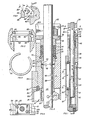
- Fig. 1 is a sectional view of a butterfly valve structure which incorporates the stem retention device comprising the present invention; Fig. 2 is an enlarged fragment of Fig. 1 illustrating the stem retention device within the stem bore; Fig. 3 is an enlarged section of the stem retention device of Fig. 1 and 2 showing the split retainer ring prior to insertion; Fig. 4 is an enlarged section of the groove in the bore of the valve body with the retainer ring and support ring of the retention device shown in section removed from the groove;
- Fig. 5 is a top plan of the split retainer ring; and
- Fig. 6 is a top plan generally along line 6-6 of Fig. 1.
- Referring now to the drawings for a better understanding of the invention, and more particularly to Fig. 1, the butterfly valve structure generally indicated at 10 comprises a
body 12 having aflow passage 14 therethrough. A butterfly valve disc indicated generally at 16 is mounted within the flow passage for movement between open and closed positions and comprises afront face 18, arear face 20, and an outerperipheral sealing surface 22 extending about the outer periphery ofvalve disc 16 to form a generally spherical sealing surface.Rear face 20 has anintegral sleeve 24 and a shaft or stem 26 fitting withinsleeve 24 is secured thereto bysuitable pins 28 to connectvalve disc 16 for rotation withstem 26. Ahandle 30 is secured to the outer end ofstem 26 for manual gripping and rotation ofstem 26. - A seat assembly generally indicated at 32 has a
resilient seal element 34 which is adapted to engage in sealing relation theadjacent sealing surface 22 ofbutterfly valve disc 16. Aretainer plate 36 is secured tobody 12 to holdseat assembly 34 in position.Body 12 has abore 38receiving stem 26. A sleeve bearing 40 is positioned withinbore 38 at the upper and lower ends ofvalve disc 16. Bore 38 has an enlargedintermediate bore portion 42.Retainer pins 44 are driven with blind openings 46 instem 26 and the ends ofpins 44 extend outwardly from the outer periphery ofstem 26 withinchamber 48 formed byintermediate bore portion 42. A large diameterend bore portion 49 receives a plurality ofpacking rings 51 therein which are supported on a metallic end ring 50. Agland ring 52 fits aroundstem 26 againstpacking rings 51 and extends upwardly into a cutout portion ofbody 12 indicated at 12A. Agland retainer plate 53 fits overring 52 and is retained bynuts 54 onstuds 55 which are mounted inbody 12.Plate 53 may be adjusted bynuts 54 to control the compressive forces exerted againstpacking rings 51 bygland ring 52. - As shown particularly in Fig. 4, an annular groove indicated generally at 56 is provided at the juncture of large
diameter bore portion 49 andintermediate bore portion 42. Groove 56 defines a lower shoulder orabutment 58, an outer peripheral wall surface 60 and an upper inclined or taperedshoulder defining surface 62 of a frusto-conical shape. A wedge support ring indicated generally at 64 fits aboutstem 26 and has an outerperipheral surface 66 with a frusto-conical or tapered end surface 68. The inner peripheral surface ofring 64 is indicated at 69. Surface 68 is arranged at around a thirty degree angle with respect to the longitudinal axis ofstem 26 andsurface 66. Taperedsurface 62 defininggroove 56 is arranged at around a forty-five degree angle with respect to the cylindrical surface defining theadjacent bore 49. Asplit retainer ring 70 is of a circular cross section and is positioned betweentapered surfaces 62 and 68 defininggroove 56 andwedge ring 64. -
Pin 44,wedge ring 64, and splitretainer ring 70 in combination withgroove 56 define the retaining means forholding stem 26 withinbore 38. In the event of any shearing ofstem 26 belowpin 44, fluid pressure fromflow passage 14 tends to urge the upper sheared portion of the stem frombore 38, the ends ofpin 44 will contact the lower surface ofwedge ring 64 andurge wedge ring 64 upwardly againstsplit ring 70. As shown in Fig. 3,split retainer ring 70 is easily inserted betweeninclined surfaces 62 and 68. Since surface 68 diverges from the longitudinal axis ofstem 26 less than the divergence ofsurface 62, upward movement ofsupport ring 64 tightly urgessplit ring 70 againstsurface 62 thereby to limit upward movement ofring 64. Thus,pin 44 is restrained from outward movement bywedge ring 64 to preventstem 26 from being blown out ofvalve body 12 upon any malfunctioning or shearing ofvalve stem 26. - The stem retaining device may be easily assembled within the bore of the valve body as
wedge ring 64 can be inserted from the upper end of the body and be seated onshoulder 58. Then,split ring 70 may be inserted betweensurfaces 62 and 68 to holdwedge ring 64 in position. End packing ring 50 separatespacking rings 51 fromwedge ring 64 and may be inserted within the bore along withpacking rings 51. Then,gland ring 52 andretainer plate 53 are added to holdpacking rings 51 and the retaining means within the bore.Nuts 54 are threaded onstuds 55 to profice a predetermined compressive loading ofpacking rings 51. - Tapered
surfaces 62 and 68 may be formed, if desired, of different angles with respect to the longitudinal axis ofstem 26 and function in a satisfactory manner so long assurface 62 is disposed at an angle greater than the inclination of surface 68 with respect to the longitudinal axis ofstem 26 to insure thatring 70 is wedged tightly betweensurfaces 62 and 68. For example,surface 62 could be positioned between around thirty-five degrees (35°) and ninety degrees (90°) with respect to the longitudinal axis ofstem 26 and function in a satisfactory manner. - It is to be understood that means other than
pins 44 could be provided onstem 26 to engagering 64 such as an annular shoulder, or separate snap ring in an annular groove instem 26, for example.
Claims (4)
Applications Claiming Priority (2)
| Application Number | Priority Date | Filing Date | Title |
|---|---|---|---|
| US06/043,554 US4270730A (en) | 1979-05-29 | 1979-05-29 | Means to retain a valve stem |
| US43554 | 1979-05-29 |
Publications (3)
| Publication Number | Publication Date |
|---|---|
| EP0029060A1 EP0029060A1 (en) | 1981-05-27 |
| EP0029060A4 EP0029060A4 (en) | 1982-11-08 |
| EP0029060B1 true EP0029060B1 (en) | 1985-07-10 |
Family
ID=21927749
Family Applications (1)
| Application Number | Title | Priority Date | Filing Date |
|---|---|---|---|
| EP80901135A Expired EP0029060B1 (en) | 1979-05-29 | 1980-03-25 | Means to retain a valve stem |
Country Status (4)
| Country | Link |
|---|---|
| US (1) | US4270730A (en) |
| EP (1) | EP0029060B1 (en) |
| CA (1) | CA1132524A (en) |
| WO (1) | WO1980002731A1 (en) |
Families Citing this family (12)
| Publication number | Priority date | Publication date | Assignee | Title |
|---|---|---|---|---|
| US4589628A (en) * | 1982-09-10 | 1986-05-20 | General Signal Corporation | Unitary bearing and locator assembly for rotatable valves |
| US4541612A (en) * | 1984-04-03 | 1985-09-17 | Keystone International, Inc. | Rotatable shaft assembly |
| US4659064A (en) * | 1986-08-01 | 1987-04-21 | Keystone International, Inc. | Apparatus for fixing the position of a valve element shaft in a bore |
| DE4208323C2 (en) * | 1992-03-16 | 1994-03-31 | Klein Schanzlin & Becker Ag | Gland packing |
| SE508637C2 (en) * | 1997-04-28 | 1998-10-26 | Weiss Technic Sweden Ab J | Control valve with mainly horizontal valve shaft and method for control valve manufacturing |
| US7172172B2 (en) * | 2003-07-28 | 2007-02-06 | Fisher Controls International, L.L.C. | Valve packing removal device |
| US8727310B2 (en) * | 2008-10-24 | 2014-05-20 | Fisher Controls International Llc | Packing followers for use with valves |
| TWI555940B (en) * | 2014-06-24 | 2016-11-01 | 進典工業股份有限公司 | Valve and stem package module of the same |
| US9863552B2 (en) | 2014-06-24 | 2018-01-09 | Jdv Control Valves Co., Ltd. | Fluid valve and a single shaft-sealing module thereof |
| US10077804B2 (en) * | 2015-04-24 | 2018-09-18 | Fisher Controls International Llc | Bearing for rotary control valve |
| US9958071B1 (en) * | 2017-02-15 | 2018-05-01 | Hamilton Sundstrand Corporation | High temperature shaft seal for bleed valve with roller bearings |
| RU205119U1 (en) * | 2021-01-29 | 2021-06-28 | Общество с ограниченной ответственностью "Актан" | Hermetic shut-off-check valve |
Citations (5)
| Publication number | Priority date | Publication date | Assignee | Title |
|---|---|---|---|---|
| FR1580524A (en) * | 1968-07-22 | 1969-09-05 | ||
| DE1959382A1 (en) * | 1966-11-22 | 1970-09-17 | Jean Gachot | Stopcock with rotating locking link |
| GB1211683A (en) * | 1966-10-27 | 1970-11-11 | Triangle Valve Company Ltd | Improvements in valves for controlling fluid flow |
| US3970285A (en) * | 1974-10-29 | 1976-07-20 | Henry Valve Company | Ball valve assembly |
| WO1979000126A1 (en) * | 1977-08-30 | 1979-03-22 | Gachot Jean | Rod-controlled shutter tap |
Family Cites Families (5)
| Publication number | Priority date | Publication date | Assignee | Title |
|---|---|---|---|---|
| US3038693A (en) * | 1960-08-04 | 1962-06-12 | Pacific Valves Inc | Seat adjustment for ball valves with rotatable ring |
| US3334862A (en) * | 1964-09-08 | 1967-08-08 | Yarway Corp | Ball valve having resilient seats |
| US3480253A (en) * | 1967-12-28 | 1969-11-25 | Hills Maccanna Co | Ball valve with seats for journalled ball |
| US3591133A (en) * | 1968-08-23 | 1971-07-06 | Jamesbury Corp | Butterfly valve |
| CA852063A (en) * | 1968-12-11 | 1970-09-22 | Canadian Westinghouse Company Limited | Modified butterfly trip valve |
-
1979
- 1979-05-29 US US06/043,554 patent/US4270730A/en not_active Expired - Lifetime
-
1980
- 1980-03-25 WO PCT/US1980/000322 patent/WO1980002731A1/en not_active Ceased
- 1980-03-25 EP EP80901135A patent/EP0029060B1/en not_active Expired
- 1980-04-11 CA CA349,611A patent/CA1132524A/en not_active Expired
Patent Citations (5)
| Publication number | Priority date | Publication date | Assignee | Title |
|---|---|---|---|---|
| GB1211683A (en) * | 1966-10-27 | 1970-11-11 | Triangle Valve Company Ltd | Improvements in valves for controlling fluid flow |
| DE1959382A1 (en) * | 1966-11-22 | 1970-09-17 | Jean Gachot | Stopcock with rotating locking link |
| FR1580524A (en) * | 1968-07-22 | 1969-09-05 | ||
| US3970285A (en) * | 1974-10-29 | 1976-07-20 | Henry Valve Company | Ball valve assembly |
| WO1979000126A1 (en) * | 1977-08-30 | 1979-03-22 | Gachot Jean | Rod-controlled shutter tap |
Also Published As
| Publication number | Publication date |
|---|---|
| US4270730A (en) | 1981-06-02 |
| EP0029060A4 (en) | 1982-11-08 |
| WO1980002731A1 (en) | 1980-12-11 |
| EP0029060A1 (en) | 1981-05-27 |
| CA1132524A (en) | 1982-09-28 |
Similar Documents
| Publication | Publication Date | Title |
|---|---|---|
| US4270730A (en) | Means to retain a valve stem | |
| US5228250A (en) | Tamper proof anchor bolt assembly | |
| US5076541A (en) | Tamperproof rotary valve | |
| EP0137842B1 (en) | Fire resistant gate valve | |
| US3698278A (en) | Nut member | |
| US6095493A (en) | High pressure valve | |
| US4348006A (en) | Plastic valve assembly | |
| US4659064A (en) | Apparatus for fixing the position of a valve element shaft in a bore | |
| US4540012A (en) | Temperature sensitive valve bonnet assembly | |
| EP0290113B1 (en) | Wellhead annular seal | |
| KR100393295B1 (en) | Valve assembly | |
| US4510960A (en) | Valve stem-to-bonnet backseat | |
| US2292467A (en) | Means for anchoring pins into metallic members | |
| US5102098A (en) | Tamperproof rotary valve | |
| US7063356B2 (en) | Pipe coupling | |
| EP0023133B1 (en) | Plastics butterfly valve | |
| US5730419A (en) | Dual backseat valve assembly | |
| US3525453A (en) | Sealing plug assembly | |
| US3273852A (en) | Ball valve construction | |
| US3429476A (en) | Pipe or vessel closure | |
| EP1418372A1 (en) | Thermally activated relief valve | |
| US5460467A (en) | Automatic positive locking nut and related device for locking and unlocking the nut on a shaft | |
| US4984767A (en) | Tamperproof rotary valve | |
| US5839717A (en) | Valve with improved shaft retainer | |
| EP3537013B1 (en) | Bearing for rotary control valve |
Legal Events
| Date | Code | Title | Description |
|---|---|---|---|
| PUAI | Public reference made under article 153(3) epc to a published international application that has entered the european phase |
Free format text: ORIGINAL CODE: 0009012 |
|
| AK | Designated contracting states |
Designated state(s): FR |
|
| 17P | Request for examination filed |
Effective date: 19810416 |
|
| GRAA | (expected) grant |
Free format text: ORIGINAL CODE: 0009210 |
|
| AK | Designated contracting states |
Designated state(s): FR |
|
| ET | Fr: translation filed | ||
| PLBE | No opposition filed within time limit |
Free format text: ORIGINAL CODE: 0009261 |
|
| STAA | Information on the status of an ep patent application or granted ep patent |
Free format text: STATUS: NO OPPOSITION FILED WITHIN TIME LIMIT |
|
| 26N | No opposition filed | ||
| PG25 | Lapsed in a contracting state [announced via postgrant information from national office to epo] |
Ref country code: FR Free format text: LAPSE BECAUSE OF NON-PAYMENT OF DUE FEES Effective date: 19891130 |
|
| REG | Reference to a national code |
Ref country code: FR Ref legal event code: ST |