EP0029014A2 - Vorrichtung zum wahlweisen Schärfen einer Rakete, entweder mittels eines elektrischen Signals oder durch Handbetätigung - Google Patents
Vorrichtung zum wahlweisen Schärfen einer Rakete, entweder mittels eines elektrischen Signals oder durch Handbetätigung Download PDFInfo
- Publication number
- EP0029014A2 EP0029014A2 EP80830089A EP80830089A EP0029014A2 EP 0029014 A2 EP0029014 A2 EP 0029014A2 EP 80830089 A EP80830089 A EP 80830089A EP 80830089 A EP80830089 A EP 80830089A EP 0029014 A2 EP0029014 A2 EP 0029014A2
- Authority
- EP
- European Patent Office
- Prior art keywords
- cylindrical
- sleeve
- key
- missile
- arming
- Prior art date
- Legal status (The legal status is an assumption and is not a legal conclusion. Google has not performed a legal analysis and makes no representation as to the accuracy of the status listed.)
- Withdrawn
Links
Images


Classifications
-
- F—MECHANICAL ENGINEERING; LIGHTING; HEATING; WEAPONS; BLASTING
- F42—AMMUNITION; BLASTING
- F42C—AMMUNITION FUZES; ARMING OR SAFETY MEANS THEREFOR
- F42C15/00—Arming-means in fuzes; Safety means for preventing premature detonation of fuzes or charges
- F42C15/40—Arming-means in fuzes; Safety means for preventing premature detonation of fuzes or charges wherein the safety or arming action is effected electrically
-
- F—MECHANICAL ENGINEERING; LIGHTING; HEATING; WEAPONS; BLASTING
- F42—AMMUNITION; BLASTING
- F42C—AMMUNITION FUZES; ARMING OR SAFETY MEANS THEREFOR
- F42C14/00—Mechanical fuzes characterised by the ammunition class or type
Definitions
- This invention relates to a dual device for the arming of a missile either by means of an electrical signal or by mechanical manual operation.
- the subject of the patent is a safety device Whichallows the actuator which arms the missile to be operated either by manually rotating a key or by the operation of an electric motor once the device has been prepared for this by the predetermined extraction of the key.
- the object of this invention is the realization of a device for the arming of a missile which in the inhibited position is protected with absolute guarantee from undesired operation of the actuator either due to events
- a further object is the realization of a device for the arming of a missile which once the arming by mechanical means has been determined cannot be disarmed electrically.
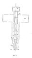
- first crown wheel (9) rigidly connected to the case (15); a second crown wheel (8) which is extended in the hollow shaft (24); two pinions (16) and (16') whose hubs are keyed onto the shaft (17) which is rotated by the rotation of the said axes. Therefore the two possible inlets for motion are :
- the mechanism constituted by the gears (11) and (10) and by the rod (13) that operates the actuator (14) is of conventional design, it may be substituted by other mechanisms and does not form a'specific subject of the patent.
- the input movement by means of an electrical signal occurs as follows : an electric motor (19) via the reduction drive (20) causes the worm drive (21) to rotate and this communicates the motion to the Gear (12).
- This crown wheel is extended outwards into the hollow shaft(24) from which it receives motion in the manner described below.
- the said hollow shaft houses the sleeve (5) that can run longitudinally.
- This sleeve in its upper part (28) is of reduced diameter with respect to the internal diameter of the said hollow shaft (24) so that it leaves a circular space for housing the helical spring (7) which performs its thrust action between the upper wall of the inside of the said hollow shaft(24) and the upper zone of the part of the sleeve (5) which is not of reduced diameter.
- the sleeve (5) contains a hole (26) through which the axis (3") of a piston (3) passes.
- This piston will now be described.
- a double slit (27) in the hollow shaft (24) corresponding to the hole which allows the longitudinal movement of the said axis(3")of the piston (3) solidly with the sleeve (5).
- sleeve (5) In the lower end of the said sleeve (5) there is a housing of square section for the insertion of the operating key.
- the upper part of reduced external diameter (28) of sleeve (5) is hollowed internally and has a projection (90) in the form of a sector of a circle having an aperture equal to an angle of about 60 degrees.
- the said shaft (6) possesses a longitudinal channel (91) obtained by the removal of a circular sector having an aperture equal to an angle ⁇ which is 50 degrees more than the angle ⁇ referred to above and thus about 110 degrees.
- Figure 3 shows the plan of the entrance hole (29) for the key which as will be seen is provided with an entrance slot, which allows the passage of a pin (32), with which the key is furnished, only when the key itself assumes fixed angular positions in its seat.
- the seat (30A) in which the pin can rest when the key is rotated 90 degrees with respect to its input position. In this position the key can rest when the key is rotated 90 degrees with respect to its input position. In this position the key cannot be rotated or be removed as will now be described.
- the piston (3) carries a cylindrical head 3' keyed onto the axis 3".
- the piston which, as seen previously rotates in a piece with the sleeve (5) and with the hollow shaft (24), assumes a fixed angular position (i.e. that shown in figure 1) the said cylindrical head 3' engages with its lower part in a seat (4) and with its upper part in a seat (4') according to the position along the vertical that the piston assumes when it follows the movement of sleeve (5) within the hollow shaft (24).
- the key terminates in a square-shaped point (33) suitable for insertion in the square seat (31) of the sleeve (5).
- the said cylindrical part terminates in a ledge (43) which will be mentioned later.
- the piston is thus blocked and in its turn prevents the rotation of the hollow shaft (24) and therefore of the crown wheel (8).
- crown wheel (8) thus being blocked and the pinion being . prevented in the motion of rotation, crown wheel (9) will also be blocked and the operation of the device will not be pos sible not even by means of the electric motor.
- the whole device is therefore in the safety position. If one wishes to arm the missile by means of the key it is necessary to proceed as follows: the key is pushed towards the inside until it causes the ledge (43)to come in contact with external wall of the key entrance hole.
- the key is now free to rotate and therefore it is made to rotate 90 degrees anticlockwise.
- the head of the piston (3') which will have rotated through 90 degrees with respect to the starting position when it was inserted in the seat (4) will be housed in another seat (not shown in the figure) which, unlike seat (4) which is not provided with a bottom and therefore communicates with the outside, is however provided with a ledge on which the said head of the piston (3') rests so blocking the de scent of sleeve (5) down to the bottom.
- the missile is thus now armed and the key extracted.
- the seat (4) in which the piston is hous ed in the disarmed position of the missile communicates with the outside allowing the bottom of the head of the piston (3') to be seen and therefore providing away of knowing if the missile is disarmed (piston visible) or arm ed (piston not visible).
- a spacer (49) shown in figure 5 is inserted in this space. It is provided with a channel in which the cylindrical part of the key (41) is placed.
- the 90 degrees movement in a clockwise direction brings the pin (32) into coincidence with the slot (30 A) and so the key can be extracted.
- a suitable key will be inserted, this being practically formed by a simple cylindrical body furnished with a handle, terminating in a square form analogous to the square-shaped point (33) and not furnished with pin (32).
- the said key can therefore, enter freely and cause the sleeve (5) to rotate clockwise 90 degrees which will disarm the missile.
- the scope of this invention is a dual device for-the arming of the missile either by means of an electrical sig nal or by manual mechanical operation characterised by the fact that it includes a differential element formed by a first crown wheel, a second crown wheel and a pair of coaxial pinions whose hubs are keyed onto the output shaft coaxial with the two said crown wheels, and the extension downwards of the said second crown wheel into the second shaft which is solid with it and is able to transmit the arming or disarming command by means of the mechanism to the arm ing actuation of the missile and in which the said first crown wheel is solid with the differential case which by means of the unidirectional mechanical devices receives the operational command from an electric motor transmitting it to the said output shaft via the said pinions when the said second crown wheel is blocked and in which the said second crown wheel, via mechanical coupling elements, can be operated manually by means of a key which sets it in rotation causing the entrainment of the said pinions and therefore the rotation of the said output shaft while the said first crown wheel is
- the unidirectional mechanical devices for the transmission of the electric motor operational command and of the case of the differential are formed by a reduction gear consisting of a pair of enmeshed gears the first of which is solid with the axis of the motorand the second is keyed onto a first shaft on which is also placed a worm drive that operates a gear at one end of a second shaft perpendicular to the said first shaft and which has a bevel gear at the other end enmeshed with another bevel gear which is solid with and drives externally the said case of the differential.
- the mechanical coupling elements are formed by a sleeve consisting of two coaxial cylindrical elements of equal internal diameter and of which the upper one has an external diameter less than the other, which is provided with an internal seat towards the bottom of square cross section; a hollow shaft constituting the extension of the said second crown wheel and of which the internal diameter is equal to the external diameter of the cylindrical element of the said sleeve having the greater diameter; a helical spring of a diameter such as will fit in the space between the outside surface of the said cylindrical element of the sleeve with lesser external diameter and the internal surface of the said hollow-shaft; a piston formed by a cylindrical body to one side of which a cylindrical head is fixed, the lower part of which being fixed to the upper part by means of screws can be removed; and in which the said upper part of the said sleeve is also hollow inside and is provided with a projection in the form of a circular sector having an aperture equal to an angle ⁇ while the said lower part of the sleeve has a hole perpendicular to its
- the arming key also consitutes a part of the invention.
- the said key consists of a cylindrical body provided above with a handle and terminating at the other end with a square shaped point for the insertion in the said square shaped seat of the said sleeve and the cylindrical part situated above the said square-shaped point being also furnished with a pin for insertion in the two said 90 degree slots with which the said round aperture in the said body containing seats is provided, and the said cylindrical part terminating with a shoulder ledge, the said cylindrical body constituting the key being further provided with an axial hole for the housing of a pin inserted in it, which, being provided above with a threaded part which is screwed into a corresponding threaded hole with which the upper part of the said axial hole terminates, can be made to advance or recede longitudinally and therefore protrude more or less from the said lower end of the said key by the manual rotary movement obtained from a handle with which the said pin is provided in the upper part.
Landscapes
- Engineering & Computer Science (AREA)
- General Engineering & Computer Science (AREA)
- Control Of Position, Course, Altitude, Or Attitude Of Moving Bodies (AREA)
- Transmission Devices (AREA)
Applications Claiming Priority (2)
| Application Number | Priority Date | Filing Date | Title |
|---|---|---|---|
| IT5079879 | 1979-11-09 | ||
| IT50798/79A IT1164018B (it) | 1979-11-09 | 1979-11-09 | Dispositivo duale per l'armamento di un missile sia per mezzo di segnale elettrico che per azionamento meccanico manuale |
Publications (2)
| Publication Number | Publication Date |
|---|---|
| EP0029014A2 true EP0029014A2 (de) | 1981-05-20 |
| EP0029014A3 EP0029014A3 (de) | 1981-09-16 |
Family
ID=11273737
Family Applications (1)
| Application Number | Title | Priority Date | Filing Date |
|---|---|---|---|
| EP80830089A Withdrawn EP0029014A3 (de) | 1979-11-09 | 1980-10-30 | Vorrichtung zum wahlweisen Schärfen einer Rakete, entweder mittels eines elektrischen Signals oder durch Handbetätigung |
Country Status (2)
| Country | Link |
|---|---|
| EP (1) | EP0029014A3 (de) |
| IT (1) | IT1164018B (de) |
Family Cites Families (1)
| Publication number | Priority date | Publication date | Assignee | Title |
|---|---|---|---|---|
| US4019441A (en) * | 1976-03-08 | 1977-04-26 | The United States Of America As Represented By The Secretary Of The Army | Warhead enable switch for use in a missile |
-
1979
- 1979-11-09 IT IT50798/79A patent/IT1164018B/it active
-
1980
- 1980-10-30 EP EP80830089A patent/EP0029014A3/de not_active Withdrawn
Also Published As
| Publication number | Publication date |
|---|---|
| IT1164018B (it) | 1987-04-08 |
| EP0029014A3 (de) | 1981-09-16 |
| IT7950798A0 (it) | 1979-11-09 |
Similar Documents
| Publication | Publication Date | Title |
|---|---|---|
| JPH0452363Y2 (de) | ||
| US6003910A (en) | Electric lock for vehicle door | |
| US5597058A (en) | Hub lock for vehicle | |
| US6234039B1 (en) | Steering lock for a motor vehicle steering column | |
| US5029915A (en) | Vehicle door locking system | |
| CN110029877B (zh) | 一种手自一体双驱锁体 | |
| EP0029014A2 (de) | Vorrichtung zum wahlweisen Schärfen einer Rakete, entweder mittels eines elektrischen Signals oder durch Handbetätigung | |
| US4106316A (en) | Keyless combination locks | |
| US4108016A (en) | Device of preventing reverse transmission of motion in a gear train | |
| US3748880A (en) | Lock assemblies particularly suitable for motor vehicles | |
| JPS6252285A (ja) | アクチユエ−タ | |
| US2918869A (en) | Gyroscope driving means | |
| EP0265826B1 (de) | Lenksperre eines Kraftfahrzeugs | |
| GB2030096A (en) | A vehicle anti-theft device | |
| US3309942A (en) | Push-pull handwheel and motor drive | |
| US3367267A (en) | Non-gyrating projectile fuse | |
| US3463891A (en) | Control units for valve actuators | |
| EP0187873A1 (de) | Lenkspindelschloss ohne Schlüssel | |
| US2845801A (en) | Engine starting apparatus | |
| USH492H (en) | Safe/arm device | |
| JP2849334B2 (ja) | 電子錠 | |
| US3238800A (en) | Remotely controlled rear view mirror | |
| DE3824376C1 (de) | ||
| US2592374A (en) | Valve actuating mechanism | |
| US4185662A (en) | Apparatus for actuating operating valve unit for winch |
Legal Events
| Date | Code | Title | Description |
|---|---|---|---|
| PUAI | Public reference made under article 153(3) epc to a published international application that has entered the european phase |
Free format text: ORIGINAL CODE: 0009012 |
|
| AK | Designated contracting states |
Designated state(s): DE FR GB NL SE |
|
| 17P | Request for examination filed |
Effective date: 19810318 |
|
| PUAL | Search report despatched |
Free format text: ORIGINAL CODE: 0009013 |
|
| AK | Designated contracting states |
Designated state(s): DE FR GB NL SE |
|
| R17P | Request for examination filed (corrected) |
Effective date: 19810902 |
|
| STAA | Information on the status of an ep patent application or granted ep patent |
Free format text: STATUS: THE APPLICATION IS DEEMED TO BE WITHDRAWN |
|
| 18D | Application deemed to be withdrawn |
Effective date: 19830118 |
|
| RIN1 | Information on inventor provided before grant (corrected) |
Inventor name: NOTARGIACOMO, ENZO M. Inventor name: MARROCCO, FRANCESCO |