EP0028838A2 - Device for writing in braille - Google Patents
Device for writing in braille Download PDFInfo
- Publication number
- EP0028838A2 EP0028838A2 EP80106953A EP80106953A EP0028838A2 EP 0028838 A2 EP0028838 A2 EP 0028838A2 EP 80106953 A EP80106953 A EP 80106953A EP 80106953 A EP80106953 A EP 80106953A EP 0028838 A2 EP0028838 A2 EP 0028838A2
- Authority
- EP
- European Patent Office
- Prior art keywords
- embossing
- die
- dies
- bar
- stamping
- Prior art date
- Legal status (The legal status is an assumption and is not a legal conclusion. Google has not performed a legal analysis and makes no representation as to the accuracy of the status listed.)
- Withdrawn
Links
Images


Classifications
-
- B—PERFORMING OPERATIONS; TRANSPORTING
- B41—PRINTING; LINING MACHINES; TYPEWRITERS; STAMPS
- B41J—TYPEWRITERS; SELECTIVE PRINTING MECHANISMS, i.e. MECHANISMS PRINTING OTHERWISE THAN FROM A FORME; CORRECTION OF TYPOGRAPHICAL ERRORS
- B41J3/00—Typewriters or selective printing or marking mechanisms characterised by the purpose for which they are constructed
- B41J3/32—Typewriters or selective printing or marking mechanisms characterised by the purpose for which they are constructed for printing in Braille or with keyboards specially adapted for use by blind or disabled persons
Definitions
- the invention relates to a device for writing Braille with an embossing die provided with recesses for a dot line, on which a web to be embossed can be moved transversely to the line direction, and with a row of embossing stamps arranged according to the dot line, each of which is optionally based on coded signals an embossing stroke for embossing a point of the line can be controlled by means of an actuating member and are guided in stamp bores in a guide plate.
- each individual embossing stamp is connected to an associated electromagnet which exerts the embossing force.
- the control of the individual dies is carried out by energizing the associated electromagnet.
- the energy required for the respective control signal is therefore relatively large because it must also exert the force required for the stamping process.
- the return stroke of the stamping dies is carried out by springs, the force of which must also be overcome during the stamping stroke. Because of the high forces to be transmitted, the device must be relatively heavy. The masses to be moved with each stamp movement are very large, so that the working speed is relatively low.
- the object of the invention is therefore to implement a device of the type mentioned in such a way that the embossing process can be carried out with very low energy requirements for the signals driving the individual actuators, so that the device can be easily designed and designed for a high working speed.
- the force required for the embossing process is applied exclusively by the drivable embossing bar; the actuators only serve to control the embossing dies by bringing the embossing dies into and out of engagement with the embossing bar. Since the direction of movement of the actuating members runs transversely to the punch stroke direction, the actuating members lie completely outside the force flow of the force applied during the stamping process. The signals supplied to the actuators therefore require very little energy; the forces occurring between the actuators and the dies are very low, so that the parts required for power transmission very easily ge can be selected. The small masses to be moved enable a very high working speed.
- The; Force flow for the embossing process runs directly from the embossing bar in the longitudinal direction of the embossing stamp.
- these embossing stamp carriers are moved in such a way that all embossing stamps of the entire line are actuated in the manner required for a specific character, but only a single embossing die is brought into engagement with the embossing stamps at the point at which the character is to appear.
- the force required for the embossing process must also be applied by those actuators which control the six stamp carrier.
- a complete line of dots cannot be used for each embossing process, but only a single braille character can be embossed, so; that as many embossing processes are required to create a character line as the line contains characters.
- the holding-down device is expediently designed as a comb, in the tine slots of which an embossing die is movably guided, each embossing die having a collar as a stop in its section arranged between the holding-down comb and the stop surface. It is thus achieved in a very simple manner in terms of construction that the stamping die can carry out the required pendulum movement without the hold-down device impairing this pendulum movement.
- the embossing dies each have a shoulder or collar, which with the return stroke movement with one Guide plate connected stop surface engages, which is expediently formed by a comb plate arranged below the guide plate.
- the dies are suspended in a freely swinging manner, so that no further constructive measure is required to guide the dies in their longitudinal direction when the dies are out of engagement with the die at one end.
- the comb shape of this stop surface enables easy assembly of the dies.
- the actuating members are advantageously electromagnets with a direction of movement extending transversely to the punch stroke direction, each of which is connected to an embossing punch via an actuating tab.
- the actuating tabs allow a deflection perpendicular to the direction of movement of the electromagnets without having to provide movable guides on the embossing dies or without a retroactive effect of the embossing force on the electromagnets.
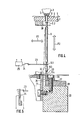
- a web 1 made of strong paper or thin cardboard is moved by a drive device, of which only a driven star wheel 2 is indicated, under an embossing die 3 / which is fastened in a machine frame 4 and has depressions 5 ( Fig.4).
- the web 1 runs over a guide surface 6, of which only a section is shown in FIG. 1.
- In the guide surface 6 there is a guide plate 7, in which 5 punch bores 8 are arranged in a row under the depressions.
- Embossing dies 9 protrude through the punch bores 8, the upper ends of which are rounded off in a hemispherical manner corresponding to the depressions 5. If the Embossing stamp 9 are moved upwards, they emboss approximately hemispherical bulges in the web 1, which form the points from which the individual characters. the braille are composed.
- a belt drive 10 which is only indicated in FIG. 1, drives an eccentric shaft 11 on which a plurality of eccentrics 12 are seated next to one another, each of which eccentrically carries a roller bearing 13.
- the eccentric shaft 11 is rotatably supported by means of roller bearings 14 in arms 15 which are attached to a support bracket 16 which is mounted in the machine frame 4 in a height-adjustable manner.
- the support bracket 16 can be adjusted against the force of a plate spring assembly 18 in the machine frame 4 by means of a screw 17 (FIG. 3).
- roller bearings 13 are guided in C-shaped supports 19 which are open on one side and which are connected to a common embossing bar 20.
- two vertical pins 21, which are attached to the support beam 16 engage in mutually aligned bores 22 of the supports 19, which are guided so that they can move in the vertical direction relative to the support beam 16.
- each embossing die is connected to a horizontal actuating glass 23 at a tapered section 9.1 located in its lower region grips around the tapered section 9.1 in a fork-like manner.
- the actuation tab 23 is connected to an armature 24 of an electromagnet 25.
- the lower end of the die 9 is supported on a stop surface 26 of the die bar 20.
- the stop surface 26 is formed by a hardened steel strip 27 which lies on a stop rail 28 which is connected to the embossing bar 20 by means of a screw 29.
- the die 9 When the electromagnet 25 exerts a tensile force in the horizontal direction (arrow P1), the die 9 is pivoted into the position shown in broken lines in FIG. 4, its lower end disengaging from the stop surface 26. If the lower end of the stamp 9 is above the stop surface 26, the stamp 9 is raised during a stroke of the stamping beam 20 and carries out an stamping process. However, if the lower end of the stamp 9 is located to the side of the path of movement of the stop surface 26, the stamp 9 is not lifted during the lifting movement of the stamping beam 20, so that no stamping takes place. In this way, the electromagnets 25 can control the stamping dies 9 assigned to them in such a way that the stamping stamps 9 either carry out an embossing or not during the lifting movement of the embossing bar 20.
- the dies 9 have a collar 9.2 below the guide plate 7, which engages with a comb plate 30 attached under the guide plate 7.
- the comb plate 30 thus forms a stop for each collar 9.2 of the die 9.
- each die 9 Via an angle rail 31 screwed onto the side of the embossing bar 20, a hold-down 32 designed as a comb is attached, in the tine slots 33 of which a tapered section 9.3 of the embossing die 9 is guided vertically and movably in the transverse direction. Below the comb 32, each die 9 carries a collar 9.4, which engages with the underside of the comb 32 in order to take the die 9 with it when the embossing bar 20 moves downward. The direction of movement of the die 9 is shown by the arrow P2.
- piezoelectric bilaminar bending elements 34 (FIG. 5) can be used as actuators for the swiveling movement of the embossing dies 9, said bending elements performing a bend when an electrical voltage is applied, as is indicated in FIG.
- the piezoelectric bending elements 34 can also each be arranged parallel to the associated die 9 and connected to it. This gives a particularly space-saving structure.
- Fig. 2 it can be seen that the embossing die 3 is pivotally mounted on both sides in the machine frame 4 by means of a pivot pin 35.
- a coni s locking pin 36 which is displaceable in its longitudinal direction, holds the embossing die 3 on both sides in the operating position shown. After this. When the two locking bolts 36 are loosened, the embossing die 3 can be folded up, for example to enable monitoring or cleaning in the embossing area.
- the actuation of the electromagnet 25 occurs by an in Fig. 1 only indicated the control circuit 37 1 for each revolution of the eccentric shaft 11 receives a signal from a photo cell 38. Coded signals are supplied to the control circuit 37 via a control input 39, from which it follows whether or not an embossing should take place at the point of the web 1 located above an embossing stamp 9 during the next rotation of the eccentric shaft 11. Accordingly, the die 9 is either held in engagement with the stop surface 26 or pivoted out of engagement with the stop surface 26. Since the dies 9 are guided in the die bores 8 and on the comb plate 30 so that a free oscillation is possible, the force to be exerted by the actuators 25 and 34 for the pendulum movement of the dies 9 is very low. The game of the stamp 9 in the stamp holes 8 is also such that the paper dust accumulating during the stamping process can fall down and that self-centering of the stamp 9 in the recess 5 of the stamping die is possible during the stamping process.
- the pendulum movement of the stamping dies 9 can only be carried out when the stamping bar 20 is is at least approximately in its lower position.
- the lifting movement is synchronized with the pendulum movement of the stamping dies 9 by means of the photocell 38.
- FIGS. 7 and 8 differs from the embodiment according to FIGS. 1-5 essentially in that on one side of the series of Embossing dies 9 are arranged a series of electromagnets 40 each associated with an individual embossing die 9.
- Each electromagnet 40 each has a U-shaped core 41, the two ends of which are turned towards the die 9.
- One or both core legs each carry a magnetic winding 42. All electromagnets 40 are cast into a common electromagnetic strip 43 (FIG. 8).
- the surface of the electromagnets 40 facing the embossing dies 9 is provided with a friction-reducing plastic layer 44, which consists for example of PTFE.
- a permanent magnet strip 45 is arranged, which is attached to a carrier 46.
- the carrier 46 is connected to an eccentric 47 mounted in the machine frame, which is in drive connection with the eccentric shaft 11 for the lifting movement of the embossing bar 20 via a slip-free belt drive 48.
- the permanent magnetic strip 45 is in synchronism transversely to the direction of the back die 9 with the lifting movement of the emboss bar 20 back and forth.
- the excitation of the electromagnets 40 is controlled by the control circuit 37 in such a way that at the beginning of each lifting movement of the embossing bar 20 only the electromagnets 40 are energized for those embossing dies 9 which are to carry out an embossing process.
- On the stamping dies 9 exerted by the electromagnets 40 of magnetic force is groES s er than the magnetic holding force of the permanent magnet strip 45, moving away at the beginning of the stroke movement of the stamping bar 20 laterally from the dies. 9 Therefore, those dies 9 whose electromagnet 40 is energized at this moment are held on the electromagnet 40 and come into engagement with the stop surface 26 of the embossing bar 20.
- the other dies 9, the respectively associated electromagnet 4o of which is not energized follow the permanent magnet strip 45 and are pivoted into the position indicated by dash-dotted lines in FIG. 8 so that they do not engage with the stop surface 26.
- the control circuit 37 can be designed such that shortly after the start of the lifting movement of the embossing bar 20 it also switches off those electromagnets 40 which were initially excited and which held the respectively assigned embossing die 9.
- a fixed comb strip 49 (FIG. 9) is provided, the comb teeth of which 50 form guide surfaces 51, on which a cylindrical one Outer surface section 52 of the respective raised die 9 rests.
- the dies 9 have a constriction 53 above the cylindrical outer surface section 52, each of which fits into a space 54 between the comb teeth 50. Therefore, the stamping dies 9 can be swung out laterally in their lower position by the permanent magnet strip 45, the constriction 53 in each case entering a tine space 54.
- Fi g. 10 shows a modified embodiment of the pre- g e die 3.
- strip-shaped projection 60 is provided at a distance from the series of depressions. 5
- This projection 60 causes the paper or cardboard web 1 to be pulled out of the depressions 5 under the pulling action of the star wheel 2. This prevents the parts of the paper or cardboard web 1 pressed into the recesses 5 from getting caught in the recesses 5 when the paper or cardboard web 1 is being transported. This measure allows the force required for the transport of paper or cardboard to be significantly reduced; damage is also avoided.
Landscapes
- Printers Characterized By Their Purpose (AREA)
- Credit Cards Or The Like (AREA)
- Printing Methods (AREA)
- Machines For Manufacturing Corrugated Board In Mechanical Paper-Making Processes (AREA)
Abstract
Bei einer Vorrichtung zum Schreiben von Blindenschrift läuft eine zu prägende Bahn unter einer Prägematrize (3) entlang, die mit Vertiefungen (5) für eine zu prägende Punktzeile versehen ist. Unter der Prägematrize (3) ist eine Reihe von Prägestempeln (9) angeordnet. Mittels quer zur Stempelhubrichtung bewegbarer Betätigungsorgane (23,24,25) sind die Prägestempel (9) wahlweise aufgrund von codierten Signalen in und außer Eingriff mit einem Prägebalken (20) bewegbar, der kontinuierliche Hubbewegungen ausführt. Nur die mit dem Prägebalken (20) jeweils in Eingriff stehenden Prägestempel (9) führen eine Prägung aus. Die Prägestempel (9) sind in Stempelbohrungen (8) einer Führungsplatte (7) schwenkbar aufgenommen. Ein mit dem Prägebalken (20) verbundener Niederhalter (32) in Form eines Kamms greift bei jeder Abwärtsbewegung des Prägebalkens (20) hinter jeweils einen Anschlag (9,4) jedes Prägestempels (9).In a device for writing Braille, a web to be embossed runs underneath an embossing die (3) which is provided with depressions (5) for a line of dots to be embossed. A series of stamps (9) is arranged under the stamping die (3). By means of actuating members (23, 24, 25) that can be moved transversely to the punch stroke direction, the stamping dies (9) can be moved in and out of engagement with an embossing bar (20), which executes continuous lifting movements, based on coded signals. Only the embossing dies (9), which are respectively engaged with the embossing bar (20), carry out an embossing. The embossing stamps (9) are pivotally received in stamp bores (8) of a guide plate (7). A hold-down (32) in the form of a comb connected to the embossing bar (20) engages behind each stop (9.4) of each embossing die (9) each time the embossing bar (20) moves downward.
Description
Die Erfindung betrifft eine Vorrichtung zum Schreiben von Blindenschrift mit einer mit Vertiefungen für eine Punktzeile versehenen Prägematrize, an der eine zu prägende Bahn quer zur Zeilenrichtung entlangbewegbar ist, und mit einer entsprechend der Punktzeile angeordneten Reihe von Prägestempeln, die wahlweise jeweils aufgrund von codierten Signalen zu einem Prägehub für die Prägung eines Punktes der Zeile mittels eines Betätigungsorgans ansteuerbar sind und in Stempelbohrungen einer Führungsplatte geführt werden.The invention relates to a device for writing Braille with an embossing die provided with recesses for a dot line, on which a web to be embossed can be moved transversely to the line direction, and with a row of embossing stamps arranged according to the dot line, each of which is optionally based on coded signals an embossing stroke for embossing a point of the line can be controlled by means of an actuating member and are guided in stamp bores in a guide plate.
Bei einer bekannten Vorrichtung dieser Art (US-PS 3 880 269) ist jeder einzelne Prägestempel mit einem zugeordneten Elektromagneten verbunden, der die Prägekraft ausübt. Die Ansteuerung der einzelnen Prägestempel erfolgt dadurch, daß der zugeordnete Elektromagnet erregt wird. Die für das jeweilige Ansteuerungssignal erforderliche Energie ist daher verhältnismäßig groß, weil sie auch die für den Prägevorgang erforderliche Kraft aufbringen muß.In a known device of this type (US Pat. No. 3,880,269), each individual embossing stamp is connected to an associated electromagnet which exerts the embossing force. The control of the individual dies is carried out by energizing the associated electromagnet. The energy required for the respective control signal is therefore relatively large because it must also exert the force required for the stamping process.
Bei der bekannten Vorrichtung erfolgt der Rückhub der Prägestempel durch Federn, deren Kraft beim Prägehub ebenfalls überwunden werden muß. Wegen der zu übertragenden hohen Kräfte muß die Vorrichtung verhältnismäßig schwer ausgeführt sein. Die bei jeder Prägestempelbewegung zu bewegenden Massen sind sehr groß, so daß die Arbeitsgeschwindigkeit verhältnismäßig gering ist.In the known device, the return stroke of the stamping dies is carried out by springs, the force of which must also be overcome during the stamping stroke. Because of the high forces to be transmitted, the device must be relatively heavy. The masses to be moved with each stamp movement are very large, so that the working speed is relatively low.
Aufgabe der Erfindung ist es daher, eine Vorrichtung der eingangs genannten Art so auszuführen, daß der Prägevorgang mit sehr geringem Energiebedarf für die die einzelnen Betätigungsorgane ansteuernden Signale ausgeführt werden kann, so daß die Vorrichtung leicht ausgeführt und für eine hohe Arbeitsgeschwindigkeit ausgelegt werden kann.The object of the invention is therefore to implement a device of the type mentioned in such a way that the embossing process can be carried out with very low energy requirements for the signals driving the individual actuators, so that the device can be easily designed and designed for a high working speed.
Diese Aufgabe wird mit den kennzeichnenden Merkmalen des Anspruchs 1 gelöst.This object is achieved with the characterizing features of
Die für den Prägevorgang erforderliche Kraft wird hierbei ausschließlich durch den antreibbaren Prägebalken aufgebracht; die Betätigungsorgane dienen nur zur Ansteuerung der Prägestempel, indem sie die Prägestempel in und außer Eingriff mit dem Prägebalken bringen. Da die Bewegungsrichtung der Betätigungsorgane quer zur Stempelhubrichtung verläuft, liegen die Betätigungsorgane vollständig außerhalb des Kraftflusses der beim Prägevorgang aufgebrachten Kraft. Die den Betätigungsorganen zugeführten Signale erfordern deshalb nur sehr wenig Energie; die zwischen den Betätigungsorganen und den Prägestempeln auftretenden Kräfte sind sehr gering, so daß die für die Kraftübertragung benötigten Teile sehr leicht gewählt werden.können. Die geringen zu bewegenden Massen ermöglichen eine sehr hohe Arbeitsgeschwindigkeit. Der; Kraftfluß für den Prägevorgang verläuft unmittelbar vom Prägebalken in Längsrichtung der Prägestempel.The force required for the embossing process is applied exclusively by the drivable embossing bar; the actuators only serve to control the embossing dies by bringing the embossing dies into and out of engagement with the embossing bar. Since the direction of movement of the actuating members runs transversely to the punch stroke direction, the actuating members lie completely outside the force flow of the force applied during the stamping process. The signals supplied to the actuators therefore require very little energy; the forces occurring between the actuators and the dies are very low, so that the parts required for power transmission very easily ge can be selected. The small masses to be moved enable a very high working speed. The; Force flow for the embossing process runs directly from the embossing bar in the longitudinal direction of the embossing stamp.
Für die Ansteuerung der einzelnen Prägestempel ist dabei nur eine sehr geringe Kraft erforderlich, weil die Prägestempel nur eine Pendelbewegung ausführen müssen.Only a very small force is required to control the individual dies, because the dies only have to perform a pendulum movement.
Es ist zwar bei einer Vorrichtung zum Schreiben von Blindenschrift bekannt (US-PS 3 876 052), zur Auswahl der für den Prägevorgang anzusteuernden Prägestempel Betätigungsorgane zu verwenden, deren Bewegungsrichtung quer zur Stempelhubrichtung verläuft. Bei dieser bekannten Vorrichtung werden durch diese Betätigungsorgane aber nur einzelne Prägematrizen, die jeweils die Vertiefungen für sechs Punkte aufweisen, quer zur Stempelhubrichtung bewegt. Die Prägestempel für eine vollständige Zeile von Blindenschriftzeichen sind an sechs gemeinsamen Prägestempelträgern ausgebildet. Bei jedem Prägevorgang werden diese Prägestempelträger so bewegt, daß alle Prägestempel der gesamten Zeile in der für ein bestimmtes Schriftzeichen erforderlichen Weise betätigt werden, jedoch wird nur eine einzelne Prägematrize an derjenigen Stelle in Eingriff mit den Prägestempeln gebracht', an der das Schriftzeichen erscheinen soll.It is known in a device for writing Braille (US Pat. No. 3,876,052) to use actuators for selecting the stamping dies to be controlled for the stamping process, the direction of movement of which is transverse to the stamp stroke direction. In this known device, however, only individual embossing dies, each of which has the depressions for six points, are moved transversely to the punch stroke direction by these actuating members. The stamps for a complete line of Braille characters are formed on six common stamp carriers. With each embossing process, these embossing stamp carriers are moved in such a way that all embossing stamps of the entire line are actuated in the manner required for a specific character, but only a single embossing die is brought into engagement with the embossing stamps at the point at which the character is to appear.
Bei der bekannten Vorrichtung muß ebenfalls die für den Prägevorgang erforderliche Kraft durch diejenigen Betätigungsorgane aufgebracht werden, die die sechs Prägestempelträger ansteuern. Außerdem kann bei jedem Prägevorgang nicht eine vollständige Punktzeile, sondern nur ein einzelnes Blindenschriftzeichen geprägt werden, so; daß für das Erstellen einer Schriftzeichenzeile so viele Prägevorgänge erforderlich sind, wie die Zeile Schriftzeichen enthält.In the known device, the force required for the embossing process must also be applied by those actuators which control the six stamp carrier. In addition, a complete line of dots cannot be used for each embossing process, but only a single braille character can be embossed, so; that as many embossing processes are required to create a character line as the line contains characters.
Als besonders vorteilhaft hat sich erwiesen, die Prägestempel jeweils mit einem Anschlag zu versehen, der von einem mit dem Prägebalken verbundenen Niederhalter hintergriffen wird. Dadurch wird erreicht, daß alle Prägestempel beim Rückhub des Prägebalkens durch einen formschlüssigen Eingriff zwangsläufig zurückbewegt werden, so daß keine Gefahr besteht, daß eine für den Stempelrückhub vorgesehene Federkraft in einzelnen Fällen nicht ausreicht, den Prägestempel zurückzuziehen. Außerdem ist es nicht erforderlich, beim Prägehub die Kraft derartiger Rückholfedern zu überwinden, wobei zu berücksichtigen ist, daß bei einer größeren Anzahl von Prägestempeln die Summe dieser Federkräfte sehr hoch wäre.It has proven to be particularly advantageous in each case to provide the embossing dies with a stop which is engaged behind by a hold-down device connected to the embossing bar. It is thereby achieved that all stamps are inevitably moved back by a positive engagement during the return stroke of the stamping bar, so that there is no danger that a spring force provided for the stamp return stroke is not sufficient in some cases to withdraw the stamp. In addition, it is not necessary to overcome the force of such return springs during the stamping stroke, it must be taken into account that the sum of these spring forces would be very high with a larger number of stamps.
Zweckmäßigerweise ist der Niederhalter als Kamm ausgebildet, in dessen Zinkenschlitzen jeweils ein Prägestempel bewegbar geführt ist, wobei jeder Prägestempel in seinem zwischen dem Niederhalterkamm und der Anschlagfläche angeordneten Abschnitt als Anschlag einen Bund aufweist. Dadurch ist in konstruktiv sehr einfacherweise erreicht, daß der Prägestempel die erforderliche Pendelbewegung ausführen kann, ohne daß der Niederhalter diese Pendelbewegung beeinträchtigt.The holding-down device is expediently designed as a comb, in the tine slots of which an embossing die is movably guided, each embossing die having a collar as a stop in its section arranged between the holding-down comb and the stop surface. It is thus achieved in a very simple manner in terms of construction that the stamping die can carry out the required pendulum movement without the hold-down device impairing this pendulum movement.
In Weiterbildung des Erfindungsgedankens ist vorgesehen, daß die Prägestempel jeweils einen Absatz oder Bund aufweisen, der bei der Rückhubbewegung mit einer mit der Führungsplatte verbundenen Anschlagtläche in Eingriff tritt, die zweckmäßigerweise durch eine unterhalb der Führungsplatte angeordnete Kammplatte gebildet wird. Dadurch sind die Prägestempel frei pendelnd aufgehängt, so daß keine weitere konstruktive Maßnahme erforderlich ist, um die Prägestempel in ihrer Längsrichtung zu führen, wenn die Prägestempel an ihrem einen Ende außer Eingriff mit dem Prägebalken sind. Die Kammform dieser Anschlagfläche ermöglicht eine einfache Montage der Prägestempel.In a further development of the inventive concept, it is provided that the embossing dies each have a shoulder or collar, which with the return stroke movement with one Guide plate connected stop surface engages, which is expediently formed by a comb plate arranged below the guide plate. As a result, the dies are suspended in a freely swinging manner, so that no further constructive measure is required to guide the dies in their longitudinal direction when the dies are out of engagement with the die at one end. The comb shape of this stop surface enables easy assembly of the dies.
Die Betätigungsorgane sind vorteilhafterweise Elektromagnete mit quer zur Stempelhubrichtung verlaufender Bewegungsrichtung, die jeweils über eine Betätigungslasche mit einem Prägestempel verbunden sind. Die Betätigungslaschen ermöglichen eine Auslenkung senkrecht zur Bewegungsrichtung der Elektromagnete, ohne daß dabei bewegliche Führungen an den Prägestempeln vorgesehen werden müßten oder eine Rückwirkung der Prägekraft auf die Elektromagnete möglich wäre.The actuating members are advantageously electromagnets with a direction of movement extending transversely to the punch stroke direction, each of which is connected to an embossing punch via an actuating tab. The actuating tabs allow a deflection perpendicular to the direction of movement of the electromagnets without having to provide movable guides on the embossing dies or without a retroactive effect of the embossing force on the electromagnets.
Weitere vorteilhafte Ausgestaltungen des Erfindungsgedankens sind Gegenstand von Unteransprüchen.Further advantageous refinements of the inventive concept are the subject of dependent claims.
Die Erfindung wird nachfolgend an einem Ausführungsbeispiel näher erläutert, das in der Zeichnung dargestellt ist. Es zeigt:
- Fig. 1 in einem senkrechten Schnitt die für den Prägevorgang wesentlichen Teile einer Vorrichtung zum Schreiben von Blindenschrift,
- Fig. 2 einen Teilschnitt längs der Linie II-II in Fig.1,
- Fig. 3 einen Teilschnitt längs der Linie III-III in Fig.2,
- Fig. 4 einen vergrößerten Ausschnitt aus Fig. 1 zur Darstellung von Einzelheiten der Anordnung und Betätigung der Prägestempel,
- Fig. 5 ein gegenüber der Fig. 4 abgewandeltes Betätigungselement, das als piezoelektrisches Biegeelement ausgebildet ist,
- Fig. 6 eine perspektivische vereinfachte Darstellung der in Fig. 4 gezeigten Teile,
- Fig. 7 in einem Schnitt ähnlich der Fig. 1 eine Ausführungsform, bei der die Betätigungselemente für die Prägestempel beiderseits der Reihe von Prägestempeln angeordnete Magnete sind,
- Fig. 8 die Ausführungsform nach Fig. 7 in einer vergrößerten Darstellung ähnlich der Fig. 4,
- Fig. 9 einen Teilschnitt längs der Linie IX-IX in Fig. 8,
- Fig.10 in einem Teilschnitt eine abgewandelte Ausführungsform der Prägematrize und
- Fig.11 eine weitere abgewandelte Ausführungsform in einem Teilschnitt ähnlich der Fig. 8 .
- 1 shows in a vertical section the parts of a device for writing Braille that are essential for the embossing process,
- 2 shows a partial section along the line II-II in FIG. 1,
- 3 shows a partial section along the line III-III in FIG. 2,
- 4 shows an enlarged detail from FIG. 1 to show details of the arrangement and actuation of the embossing dies,
- 5 an actuating element which is modified compared to FIG. 4 and which is designed as a piezoelectric bending element,
- 6 is a perspective simplified representation of the parts shown in Fig. 4,
- 7 in a section similar to FIG. 1, an embodiment in which the actuating elements for the dies are arranged on both sides of the row of dies,
- 8 shows the embodiment of FIG. 7 in an enlarged view similar to FIG. 4,
- 9 is a partial section along the line IX-IX in Fig. 8,
- 10 is a partial section of a modified embodiment of the embossing die and
- 11 shows a further modified embodiment in a partial section similar to FIG. 8.
Eine Bahn 1 (Fig.1) aus kräftigem Papier oder dünnem Karton wird durch eine Antriebseinrichtung, von der nur ein angetriebenes Sternrad 2 angedeutet ist, unter einer Prägematrize3/entlangbewegt, die in einem Maschinengestell 4 befestigt ist und an ihrer Unterseite Vertiefungen 5 (Fig.4) aufweist. Die Bahn 1 läuft über eine Führungsfläche 6, von der in Fig. 1 nur ein Abschnitt dargestellt ist. In der Führungsfläche 6 liegt eine Führungsplatte 7, in der unter den Vertiefungen 5 Stempelbohrungen 8 in einer Reihe angeordnet sind. Durch die Stempelbohrungen 8 ragen Prägestempel 9, deren obere Endenentsprechend den Vertiefungen 5 halbkugelförmig abgerundet sind. Wenn die Prägestempel 9 nach oben bewegt werden, prägen sie angenähert halbkugelförmige Auswölbungen in die Bahn 1, die die Punkte bilden, aus denen die einzelnen Schriftzeicher. der Blindenschrift zusammengesetzt sind.A web 1 (FIG. 1) made of strong paper or thin cardboard is moved by a drive device, of which only a driven star wheel 2 is indicated, under an embossing die 3 / which is fastened in a machine frame 4 and has depressions 5 ( Fig.4). The
Ein in Fig. 1 nur angedeuteter Riementrieb 10 treibt eine Exzenterwelle 11, auf der nebeneinander mehrere Exzenter 12 sitzen,die jeweils exzentrisch ein Wälzlager 13 tragen. Die Exzenterwelle 11 ist über Wälzlager 14 in Armen 15 drehbar gelagert, die an einem Stützträger 16 angebracht sind, der höhenverstellbar im Maschinengestell 4 angebracht ist. Mittels einer Schraube 17 (Fig.3) ist der Stützträger 16 gegen die Kraft eines Tellerfederpakets 18 im Maschinengestell 4 verstellbar.A
Die Wälzlager 13 sind in jeweils nach einer Seite offenen C-förmigen Stützen 19 geführt, die mit einem gemeinsamen Prägebalken 20 verbunden sind. Jeweils zwei senkrechte Stifte 21, die am Stützträger 16 angebracht sind, greifen in miteinander fluchtende Bohrungen 22 der Stützen 19, die auf diese Weise gegenüber dem Stützträger 16 in senkrechter Richtung beweglich geführt werden.The
Bei einer Drehung der Exzenterwelle 11 werden daher die Stützen 19 und der Prägebalken 20 auf- und abbewegt.When the
Die oberen Abschnitte der Prägestempel 9 haben in den Stempelbohrungen 8 so viel Spiel, daß die Prägestempel 9 in der in Fig. 4 gezeigten Weise geschwenkt werden kön- nen. Dazu ist jeder Prägestempel an einem in seinem unteren Bereich liegenden, verjüngten Abschnitt 9.1 mit einer horizontalen Betätigungslasclie 23 verbunden, die den verjüngten Abschnitt 9.1 gabelförmig umgreift. An ihrem anderen Ende ist die Betätigungslasche 23 jeweils mit einem Anker 24 eines Elektromagneten 25 verbunden.The upper portions of the
In der in Fig. 4 mit ausgezogenen Linien dargestellten Stellung stützt sich das untere Ende des Prägestempels 9 auf einer Anschlagfläche 26 des Prägebalkens 20 ab. Die Anschlagfläche 26 wird durch ein gehärtetes Stahlband 27 gebildet, das auf einer Anschlagschiene 28 liegt, die mittels einer Schraube 29 mit dem Prägebalken 20 verbunden ist.In the position shown in solid lines in FIG. 4, the lower end of the
Wenn der Elektromagnet 25 in horizontaler Richtung (Pfeil P1) eine Zugkraft ausübt, wird der Prägestempel 9 in die in Fig. 4 mit strichpunktierten Linien dargestellte Stellung geschwenkt, wobei sein unteres Ende außer Eingriff mit der Anschlagfläche 26 kommt. Befindet sich das untere Ende des Prägestempels 9 über der Anschlagfläche 26, so wird der Prägestempel.9 bei einem Hub des Prägebalkens 20 angehoben und führt einen Prägevorgang aus. Befindet sich das untere Ende des Prägestempels 9 jedoch seitlich neben der Bewegungsbahn der Anschlagfläche 26, so wird der Prägestempel 9 bei der Hubbewegung des Prägebalkens 20 nicht mit angehoben, so daß keine Prägung erfolgt. Auf diese Weise können die Elektromagnete 25 die ihnen zugeordneten Prägestempel 9 in der Weise ansteuern, daß die Prägestempel 9 bei der Hubbewegung des Prägebalkens 20 wahlweise entweder eine Prägung ausführen oder nicht.When the
Damit die Prägestempel 9 in der ausgelenkten Stellung, in der sie sich nicht über der Anschlagfläche 26 befinden, nicht zu tief herunterfallen können, weisen die Prägestempel 9 einen Bund 9.2 unterhalb der Fuhrungsplatte 7 auf, der mit einer unter der Führungsplatte 7 angebrachten Kammplatte 30 in Eingriff tritt. Die Kammplatte 30 bildet somit einen Anschlag für jeden Bund 9.2 der Prägestempel 9.So that the
Über eine seitlich.am Prägebalken 20 angeschraubte Winkelschiene 31 ist ein als Kamm ausgebildeter Niederhalter 32 angebracht, in dessen Zinkenschlitzen 33 jeweils ein verjüngter Abschnitt 9.3 des Prägestempels 9 senkrecht und in Querrichtung beweglich geführt ist. Unterhalb des Kamms 32 trägt jeder Prägestempel 9 einen Bund 9.4, der mit der Unterseite des Kamms 32 in Eingriff tritt, um den Prägestempel 9 beim Abwärtshub des Prägebalkens 20 nach unten mitzunehmen. Die Bewegungsrichtung der Prägestempel 9 ist durch den Pfeil P2 dargestellt.Via an angle rail 31 screwed onto the side of the
Als Betätigungsorgane für die Schwenkbewegung der Prägestempel 9 können anstelle der Elektromagnete 25 piezoelektrische bilaminare Biegeelemente 34 (Fig.5) verwendet werden, die beim Anlegen einer elektrischen Spannung eine Biegung ausführen, wie in Fig. 5 mit gestrichelten Linien angedeutet ist. Die piezoelektrischen Biegeelemente 34 können auch jeweils parallel zu dem zugehörigen Prägestempel 9 angeordnet und mit diesem verbunden sein. Dadurch erhält man einen besonders platzsparenden Aufbau.Instead of the
In Fig. 2 erkennt man, daß die Prägematrize 3 im Maschinengestell 4 beiderseits jeweils mittels eines Schwenkbolzens 35 schwenkbar gelagert ist. Ein koni- scher Rastbolzen 36, der in seiner Längsrichtung verschiebbar ist, hält auf beiden Seiten die Prägematrize 3 jeweils in der gezeigten Betriebsstellung. Nach dem. Lösen der beiden Rastbolzen 36 kann die Prägematrize 3 hochgeklappt werden, beispielsweise um eine Überwachung oder Reinigung im Prägebereich zu ermöglichen.In Fig. 2 it can be seen that the embossing die 3 is pivotally mounted on both sides in the machine frame 4 by means of a
Die Betätigung der Elektromagneten 25 erfolgt durch eine in Fig. 1 nur angedeutete Steuerschaltung 371 die von einer Fotozelle 38 bei jeder Umdrehung der Exzenterwelle 11 ein Signal erhält. Über einen Steuereingang 39 werden der Steuerschaltung 37 codierte Signale zuge.- führt, aus denen sich ergibt, ob an der jeweils über einem Prägestempel 9 befindlichen Stelle der Bahn 1 bei der nächsten Umdrehung der Exzenterwelle 11 eine Prägung erfolgen soll oder nicht. Dementsprechend wird der Prägestempel 9 entweder in Eingriff mit der Anschlagfläche 26 gehalten oder außer Eingriff mit der Anschlagfläche 26 geschwenkt. Da die Prägestempel 9 in den Stempelbohrungen 8 und an der Kammplatte 30 so geführt sind, daß ein freies Pendeln ermöglicht ist, ist die von den Betätigungsorganen 25 bzw. 34 aufzubringende Kraft für die Pendelbewegung der Prägestempel 9 sehr gering. Das Spiel der Prägestempel 9 in den Stempelbohrungen 8 ist außerdem so bemessen, daß der beim Prägevorgang anfallende Papierstaub nach unten durchfallen kann und daß eine Selbstzentrierung des Prägestempels 9 in der Vertiefung 5 der Prägematrize beim Prägevorgang möglich ist.The actuation of the
Es versteht sich, daß die Pendelbewegung der Prägestempel 9 nur vorgenommen werden kann, wenn sich der Prägebalken 20 zumindest angenähert in seiner unteren Stellung befindet. Dazu dient die Synchronisation der Hubbewegung mit der Pendelbewegung der Prägestempel 9 mittels der Fotozelle 38.It goes without saying that the pendulum movement of the stamping dies 9 can only be carried out when the stamping
Der verjüngte Prägestempelabsclmitt 9.1, an dem die gabelförmige Betätigungslasche 23 angreift, bildet zugleich eine Sollbruchstelle bei einer unzulässig hohen'Beansprchung des Prägestempels 9 auf Knickung. Auf diese Weise ist sichergestellt, daß bei einer Überlastung kein größerer Schaden in der Vorrichtung auftritt, weil nur ein verhältnismäßig leicht auszuwechselndes Teil, nämlich der Prägestempel 9, zerstört wird.The tapered embossing die end 9.1, on which the fork-shaped
Die in den Fig. 7 und 8 dargestellte Ausführungsform, bei der für gleiche Teile gleiche Bezugszeichen wie in den vorangehenden Figuren verwendet wurden, unterscheidet sich von der Ausführungsform nach den Fig. 1 - 5 im wesentlich dadurch, daß auf der einen Seite der Reihe von Prägestempeln 9 eine Reihe von jeweils einem einzelnen Prägestempel 9 zugeordneten Elektromagneten 40 angeordnet ist. Jeder Elektromagnet 40 hat jeweils einen U-förmigen Kern 41, dessen beide Schenkelenden dem Prägestempel 9 zugekehrt sind. Jeweils ein oder beide Kernschenkel tragen eine Magnetwicklung 42. Alle Elektromagnete 40 sind zu einer gemeinsamen Elektromagnetleiste 43 (Fig.8) vergossen. Die den Prägestempeln 9 zugekehrte Fläche der Elektromagnete 40 ist mit einer reibungsvermindernden Kunststoffschicht 44 versehen, die beispielsweise aus PTFE besteht.The embodiment shown in FIGS. 7 and 8, in which the same reference numerals as in the previous figures have been used for the same parts, differs from the embodiment according to FIGS. 1-5 essentially in that on one side of the series of Embossing dies 9 are arranged a series of
Auf der entgegengesetzten Seite der Reihe von Prägestem- peln 9 ist eine Permanentmagnetleiste 45 angeordnet, die an einem Träger 46 angebracht ist. Der Träger 46 ist mit einem im Maschinengestell gelagerten Exzenter 47 verbunden, der über einen schlupffreien Riementrieb 48 mit der Exzenterwelle 11 für die Hubbewegung des Prägebalkens 20 in Antriebsverbindung steht. Über diese Getriebeverbin- dung wird die Permanentmagnetleiste 45 synchron mit der Hubbewegung des Prägebalkens 20 quer zur Richtung der Prägestempel 9 hin- und herbewegt.On the opposite side of the series of dies p el n 9, a
Die Erregung der Elektromagnete 40 wird durch die Steuerschaltung 37 in der Weise gesteuert, daß zu Beginn jeder Hubbewegung des Prägebalkens 20 nur die Elektromagnete 40 für diejenigen Prägestempel 9 erregt sind, die einen Prägevorgang ausführen sollen. Die auf die Prägestempel 9 durch die Elektromagnete 40 ausgeübte magnetische Kraft ist grös- ser als die magnetische Haltekraft der Permanentmagnetleiste 45, die sich zu Anfang der Hubbewegung des Prägebalkens 20 seitlich von den Prägestempeln 9 wegbewegt. Deshalb werden diejenigen Prägestempel 9, deren Elektromagnet 40 in diesem Augenblick erregt ist, am Elektromagnet 40 festgehalten und kommen in Eingriff mit der Anschlagfläche 26 des Prägebalkens 20. Die übrigen Prägestempel 9, deren jeweils zugeordneter Elektromagnet 4o nicht erregt ist, folgen dabei der Permanentmagnetleiste 45 und werden in die in Fig. 8 mit strichpunktierten Linien angedeutete Stellung geschwenkt, so daß sie nicht mit der Anschlagfläche 26 in Eingriff treten.The excitation of the
Die jeweils von den Elektromagneten 40 festgehaltenen Prägestempel 9 gleiten bei der Prägebewegung an der Kunststoffschicht 44 entlang. Um die dabei auftretende Reibung nobh weiter zu vermindern, kann die Steuerschaltung 37 so ausgelegt sein, daß sie kurz nach'dem Beginn der Hubbewegung des Prägebalkens 20 auch diejenigen Elektromagnete 40 abschaltet, die zunächst erregt waren und den jeweils zugeordneten Prägestempel 9 festgehalten haben. Um zu verhindern, daß die dann nicht mehr von den Elektromagneten 40 gehaltenen Prägestempel 9 in diesem Augenblick auch der Magnetkraft der Permanentmagnetleiste 45 folgen, ist eine feststehende Kammleiste 49 (Fig.9) vorgesehen, deren Kammzinken 50 Führungsflächen 51 bilden, an denen ein zylindrischer Außenflächenabschnitt 52 des jeweils angehobenen Prägestempels 9 anliegt. Dadurch werden die bereits angehobenen Prägestempel 9 in senkrechter Richtung geführt und es wird verhindert, daß diese Prägestempel 9 seitlich ausschwenken können, sobald die Elektromagneten 40 abgeschaltet sind.The embossing dies 9 held by the
Um jedoch eine Schwenkbewegung derjenigen Prägestempel 9 zu ermöglichen, die außer Eingriff mit der Anschlagfläche 26 gebracht werden sollen, weisen die Prägestempel 9 oberhalb des zylindrischen Außenflächenabschnitts 52 eine Einschnürung 53 auf, die jeweils in einen Zwischenraum 54 zwischen den Kammzinken 50 paßt. Deshalb können die Prägestempel 9 in ihrer unteren Stellung durch die Permanentmagnetleiste 45 seitlich ausgeschwenkt werden, wobei jeweils die Einschnürung 53 in einen Zinkenzwischenraum 54 eintritt.However, in order to enable a pivoting movement of those dies 9 which are to be disengaged from the
Anstelle der mechanisch bewegten Permanentmagnetleiste 45 kann auch eine feststehende, im Abstand zu den Prägestempeln 9 angeordnete Elektromagnetleiste 55 vorgesehen werden (Fig.11), die aus einem oder mehreren Elektromagneten 56 besteht, deren Magnetwicklung 57 durch eine in Fig.11 strichpunktiert angedeutete Steuerschaltung 58 in Ab- hängigkeit von dem von der Fotozelle 38 oder einem anderen Geber gelieferten Signal so erregt wird, daß die Prägestempel 9 seitlich geschwenkt werden, sofern sie nicht durch den jeweils zugeordneten Elektromagneten 40 festgehalten werden. Während bei der Ausführungsform nach den Fig. 7 und 8 die Rückführung der Prägestempel 9 in die Ausgangsstellung durch die Rückbewegung der Perma- nentmagnetleiste 45 in die in den Fig. 7 und 8 gezeigten Ausgangsstellung bewirkt wird, erfolgt bei der Ausführungsform nach Fig. 11 diese Rückführung dadurch, daß der oder die Elektromagnete 56 abgeschaltet und alle Elektromagnete 40 erregt werden.Instead of the mechanically moved
Fig. 10 zeigt eine abgewandelte Ausführungsform der Prä- gematrize 3. An der einen Längskante der Prägematrize 3 ist im Abstand zu der Reihe von Vertiefungen 5 ein aus der Stirnfläche 3.1 der Prägematrize 3 herausragender, leistenförmiger Vorsprung 60 vorgesehen. Dieser Vorsprung 60 bewirkt, daß die Papier- oder Kartonbahn 1 unter der Zugwirkung des Sternrads 2 aus den Vertiefungen 5 herausgezogen wird. Dadurch wird verhindert, daß die in die Vertiefungen 5 hineingedrückten Teile der Papier- oder Kartonbahn 1 beim Transport der Papier- oder Kartonbahn 1 in den Vertiefungen 5 hängenbleiben. Durch diese Maßnahme läßt sich die für den Papier- oder Kartontransport benötigte Kraft wesentlich verringern; außerdem werden Beschädigungen vermieden. Fi g. 10 shows a modified embodiment of the pre- g e die 3. At the one longitudinal edge of the stamping die 3 a from the end face 3.1 of the embossing die 3 outstanding, strip-shaped
Claims (10)
Applications Claiming Priority (2)
| Application Number | Priority Date | Filing Date | Title |
|---|---|---|---|
| DE2945622 | 1979-11-12 | ||
| DE2945622A DE2945622C2 (en) | 1979-11-12 | 1979-11-12 | Device for writing Braille |
Publications (2)
| Publication Number | Publication Date |
|---|---|
| EP0028838A2 true EP0028838A2 (en) | 1981-05-20 |
| EP0028838A3 EP0028838A3 (en) | 1983-01-19 |
Family
ID=6085771
Family Applications (1)
| Application Number | Title | Priority Date | Filing Date |
|---|---|---|---|
| EP80106953A Withdrawn EP0028838A3 (en) | 1979-11-12 | 1980-11-11 | Device for writing in braille |
Country Status (4)
| Country | Link |
|---|---|
| US (1) | US4397573A (en) |
| EP (1) | EP0028838A3 (en) |
| JP (1) | JPS5698187A (en) |
| DE (1) | DE2945622C2 (en) |
Cited By (1)
| Publication number | Priority date | Publication date | Assignee | Title |
|---|---|---|---|---|
| US6247400B1 (en) | 1998-09-17 | 2001-06-19 | Caretec Gmbh | Apparatus for producing elevations which can be detected in a tactile manner |
Families Citing this family (10)
| Publication number | Priority date | Publication date | Assignee | Title |
|---|---|---|---|---|
| US4530286A (en) * | 1984-08-20 | 1985-07-23 | Rca Corporation | Intaglio printing plate for printing serial markings |
| JPH0410061Y2 (en) * | 1984-12-27 | 1992-03-12 | ||
| US4886380A (en) * | 1987-09-01 | 1989-12-12 | Primages, Inc. | Piezoelectric controlled electromagnetically driven printing |
| US4930914A (en) * | 1988-04-11 | 1990-06-05 | K Enterprises, Inc. | Apparatus for making tactile impressions on paper |
| JPH0737874Y2 (en) * | 1991-05-10 | 1995-08-30 | 東洋ハイブリッド株式会社 | Braille printer |
| SE508584C2 (en) | 1997-11-19 | 1998-10-19 | Index Braille Printer Co Ab | Printhead for a braille printer and a method for producing the same |
| US20050199141A1 (en) * | 2004-03-12 | 2005-09-15 | Philip Uglow | Variable embossing method and apparatus for substrates |
| WO2008103822A1 (en) * | 2007-02-21 | 2008-08-28 | Gh, Llc | Braille embosser |
| US8322483B2 (en) * | 2009-09-15 | 2012-12-04 | Robert Bosch Gmbh | Steering angle sensor |
| US9630436B2 (en) * | 2013-06-13 | 2017-04-25 | Entrust Datacard Corporation | Process of producing tactile dots, tactile dot groups, and tactile identifier marks |
Citations (3)
| Publication number | Priority date | Publication date | Assignee | Title |
|---|---|---|---|---|
| US3104053A (en) * | 1962-12-14 | 1963-09-17 | Rabinow Engineering Co Inc | Electromagnetic interposing punch |
| DE1952880A1 (en) * | 1968-10-23 | 1970-04-30 | Bull General Electric | Punching machine |
| FR2083914A5 (en) * | 1970-03-26 | 1971-12-17 | Ibm |
Family Cites Families (26)
| Publication number | Priority date | Publication date | Assignee | Title |
|---|---|---|---|---|
| US1521415A (en) * | 1921-03-15 | 1924-12-30 | John R Atkinson | Machine for making stereotype plates for printing for the blind |
| US2129065A (en) * | 1937-07-06 | 1938-09-06 | Joseph N Loop | Apparatus for printing characters |
| US2694362A (en) * | 1951-08-25 | 1954-11-16 | Remington Rand Inc | High-speed dot printer |
| US2766686A (en) * | 1953-06-11 | 1956-10-16 | Hughes Aircraft Co | High speed electro-mechanical interference-type transducer |
| US2916920A (en) * | 1957-03-11 | 1959-12-15 | Powers Samas Account Mach Ltd | Motion transmitters |
| DE1195528B (en) * | 1959-11-25 | 1965-06-24 | Siemens Ag | Line printer that can be triggered by pulses |
| US3139820A (en) * | 1961-10-16 | 1964-07-07 | Holley Carburetor Co | Print hammer mechanism |
| FR1454319A (en) * | 1964-11-28 | 1966-09-30 | Kienzle Apparate Gmbh | Improvements made to press hammer drive mechanisms in successive line printing devices |
| US3473466A (en) * | 1966-03-24 | 1969-10-21 | Friden Inc | Electrostrictive print hammer actuator in high speed printers |
| DE1938726C3 (en) * | 1969-07-30 | 1974-05-22 | Olympia Werke Ag, 2940 Wilhelmshaven | Arrangement of several magnetically actuated claw clutches in a print head for wire printers |
| BE755082A (en) * | 1969-08-25 | 1971-02-01 | Ncr Co | PRINTING HAMMER ACTUATOR |
| US3823804A (en) * | 1969-11-05 | 1974-07-16 | R Lokey | Braille typewriter |
| US3715020A (en) * | 1970-09-21 | 1973-02-06 | Teletype Corp | Wire recording and mechanism therefor |
| US3876052A (en) * | 1973-06-22 | 1975-04-08 | Triformation Systems Inc | Braille communications terminal |
| US3880269A (en) * | 1973-09-04 | 1975-04-29 | Triformation Systems Inc | Braille communication terminal |
| FR2282677A1 (en) * | 1974-08-22 | 1976-03-19 | Tretiakoff Oleg | POCKET ELECTRONIC CALCULATOR FOR THE BLIND |
| JPS52121427A (en) * | 1976-04-05 | 1977-10-12 | Shiyouichi Hiratsuka | Braille output device by electric signal input |
| JPS5823228B2 (en) * | 1976-11-16 | 1983-05-13 | キャノン・エヌ・ティー・シー株式会社 | line braille typewriter |
| DE2716617C2 (en) * | 1977-04-15 | 1982-11-04 | Triumph-Adler Aktiengesellschaft für Büro- und Informationstechnik, 8500 Nürnberg | Dot matrix print head |
| FR2408879A1 (en) * | 1977-11-10 | 1979-06-08 | Cii Honeywell Bull | DEVICE FOR CONVERTING DIGITAL ELECTRIC SIGNALS REPRESENTATIVE OF CHARACTERS INTO A SELF-LOCKED POINT REPRESENTATION, OF THE BRAILLE TYPE FOR EXAMPLE |
| NO140335C (en) * | 1977-11-24 | 1979-08-22 | Sintef Selskapet For Indust Og | BRAILLE WRITING MACHINE. |
| DE2753923A1 (en) * | 1977-12-03 | 1979-06-07 | Bosch Gmbh Robert | Braille printing unit operating quietly at high speed - has motor driven cam roller to move levers carrying embossing pins |
| NL7802332A (en) * | 1978-03-02 | 1979-09-04 | Nederlanden Staat | Braille symbols printer with electromagnetically controlled pins - has transport elements parallel to direction of writing with reset |
| JPS6016914B2 (en) * | 1978-03-28 | 1985-04-30 | キャノン・エヌ・ティー・シー株式会社 | braille line printer |
| US4183683A (en) * | 1978-03-29 | 1980-01-15 | Tokyo Metropolitan Government | Line printer for the raised-dot language of braille characters |
| US4261663A (en) * | 1978-11-27 | 1981-04-14 | Knut Grimnes | Machines for writing braille type |
-
1979
- 1979-11-12 DE DE2945622A patent/DE2945622C2/en not_active Expired
-
1980
- 1980-11-11 EP EP80106953A patent/EP0028838A3/en not_active Withdrawn
- 1980-11-12 JP JP15834280A patent/JPS5698187A/en active Granted
- 1980-11-12 US US06/205,973 patent/US4397573A/en not_active Expired - Lifetime
Patent Citations (3)
| Publication number | Priority date | Publication date | Assignee | Title |
|---|---|---|---|---|
| US3104053A (en) * | 1962-12-14 | 1963-09-17 | Rabinow Engineering Co Inc | Electromagnetic interposing punch |
| DE1952880A1 (en) * | 1968-10-23 | 1970-04-30 | Bull General Electric | Punching machine |
| FR2083914A5 (en) * | 1970-03-26 | 1971-12-17 | Ibm |
Cited By (2)
| Publication number | Priority date | Publication date | Assignee | Title |
|---|---|---|---|---|
| US6247400B1 (en) | 1998-09-17 | 2001-06-19 | Caretec Gmbh | Apparatus for producing elevations which can be detected in a tactile manner |
| DE19944099B4 (en) * | 1998-09-17 | 2008-04-30 | Caretec Ges.M.B.H. | Device for producing tactile detectable sublimities |
Also Published As
| Publication number | Publication date |
|---|---|
| EP0028838A3 (en) | 1983-01-19 |
| DE2945622A1 (en) | 1981-05-21 |
| JPS5698187A (en) | 1981-08-07 |
| DE2945622C2 (en) | 1982-08-19 |
| JPH0132784B2 (en) | 1989-07-10 |
| US4397573A (en) | 1983-08-09 |
Similar Documents
| Publication | Publication Date | Title |
|---|---|---|
| EP0236275B1 (en) | Apparatus and process for cutting rectangular pieces from a web | |
| DE2630931B2 (en) | Drive device for a dot matrix printer | |
| DE2535136A1 (en) | DEVICE FOR A PRINTER FOR HOLDING A MEDIUM TO BE PRINTED | |
| DE1910157B2 (en) | ||
| DE2526151C3 (en) | Device for shearing off rod sections on automatic multi-stage transverse transport presses | |
| DE2113374C3 (en) | Device for controllable punch drive | |
| EP0028838A2 (en) | Device for writing in braille | |
| DE4028390C2 (en) | Electromagnetic jacquard control device | |
| DE1815204A1 (en) | printer | |
| DE1952880A1 (en) | Punching machine | |
| DE917259C (en) | Printing telegraph receiver with a type wheel which has a number of type series lying outside the printing position in the idle state | |
| DE1561235A1 (en) | Control device for type printer for type selection and / or for changing the impact force of the printing hammer | |
| DE4032313A1 (en) | SEALING DEVICE FOR LOWERING BRACKET | |
| DE1474164C3 (en) | Device for punching on drawing carriers | |
| DE264371C (en) | ||
| DE2047669C3 (en) | Control device for selecting one of two transport speeds for card or strip punches | |
| DE2445279A1 (en) | PRINTING DEVICE WITH SEVERAL INDIVIDUAL ELECTROMAGNETICALLY ADJUSTABLE CHARACTER CARRIERS | |
| DE1652401A1 (en) | Automatic marking device | |
| DE484578C (en) | Pressure telegraph receiver, in which the selection of the types is caused by a rotating thumb wave and the signal currents | |
| DE1572970C (en) | Actuator | |
| DE125535C (en) | ||
| DE70842C (en) | Pressure Telegraph Receiver | |
| DE2715506C3 (en) | Document feed and printing device | |
| DE324020C (en) | Dialer for telephone systems | |
| DE1474195C3 (en) | Card punching device |
Legal Events
| Date | Code | Title | Description |
|---|---|---|---|
| PUAI | Public reference made under article 153(3) epc to a published international application that has entered the european phase |
Free format text: ORIGINAL CODE: 0009012 |
|
| AK | Designated contracting states |
Designated state(s): CH DE FR GB IT NL SE |
|
| PUAL | Search report despatched |
Free format text: ORIGINAL CODE: 0009013 |
|
| AK | Designated contracting states |
Designated state(s): CH DE FR GB IT LI NL SE |
|
| STAA | Information on the status of an ep patent application or granted ep patent |
Free format text: STATUS: THE APPLICATION IS DEEMED TO BE WITHDRAWN |
|
| 18D | Application deemed to be withdrawn |
Effective date: 19840615 |