EP0028568B1 - Eichvorrichtung - Google Patents
Eichvorrichtung Download PDFInfo
- Publication number
- EP0028568B1 EP0028568B1 EP80401548A EP80401548A EP0028568B1 EP 0028568 B1 EP0028568 B1 EP 0028568B1 EP 80401548 A EP80401548 A EP 80401548A EP 80401548 A EP80401548 A EP 80401548A EP 0028568 B1 EP0028568 B1 EP 0028568B1
- Authority
- EP
- European Patent Office
- Prior art keywords
- piston
- cylinder
- meter
- gauge
- gauge according
- Prior art date
- Legal status (The legal status is an assumption and is not a legal conclusion. Google has not performed a legal analysis and makes no representation as to the accuracy of the status listed.)
- Expired
Links
Images
Classifications
-
- G—PHYSICS
- G01—MEASURING; TESTING
- G01F—MEASURING VOLUME, VOLUME FLOW, MASS FLOW OR LIQUID LEVEL; METERING BY VOLUME
- G01F25/00—Testing or calibration of apparatus for measuring volume, volume flow or liquid level or for metering by volume
- G01F25/10—Testing or calibration of apparatus for measuring volume, volume flow or liquid level or for metering by volume of flowmeters
Definitions
- the present invention relates generally to the calibration of liquid meters and relates more particularly to a calibration gauge for liquefied gas meters. It is known that the meters must be calibrated and checked to check whether the volume of liquid passing through the meter corresponds to the value of the volume displayed on said meter during the passage of the liquid. In fact, the meter may, in the long run, present differences between the volume of liquid that it delivers and the volume of liquid that it indicates.
- standard tubes which consist of a tubular capacity closed at its ends and connectable to the meter to control.
- This capacity contains a sphere forming a piston which can move from one end to the other of the tube and in both directions under the effect of the liquid gas which circulates there.
- the display of the counter causing the emission of electrical pulses in constant number per unit of volume displayed, we count the number of pulses produced during the movement of the sphere which generates a standard volume, so that we can thus deduce the counter display error.
- the object of the present invention is in particular to remedy these drawbacks, as well as all the shortcomings of previous gauges in general, by proposing a calibration gauge for liquefied gas meters, which makes it possible to carry out measurements under permanent flow at low flow rates, which solves the problem of temperature balancing during flow, and which therefore allows meter calibration with remarkable accuracy.
- the subject of the invention is a calibration gauge for a liquid meter, such as for example a liquefied gas, and of the type essentially comprising a piston, each face of which is provided with a rod and which is mounted freely sliding in a cylinder defining a reference volume and connected to said meter to allow the measurement of the possible difference existing between the value of the volume of liquid displayed by the meter and the volume of liquid which it delivers, characterized in that each said rod is hollow and in permanent communication with the cylinder chamber.
- the free end of a hollow rod communicates with the free end of the other hollow rod by a conduit provided with at least one valve with manual or automatic control.
- one of the aforementioned hollow rods contains a conduit integral with the piston and communicating with at least one bore formed radially in the piston and emerging in an annular groove machined in the periphery of that -this.
- the periphery of the piston is provided with a friction ring axially retained by flanges, flanges or the like provided with seals.
- the communication of the hollow rods with the interior of the cylinder is ensured by orifices made radially in the said rods on each side of the piston.
- the cylinder is closed at each of its ends by a cylinder head with a friction ring for the hollow rods and in which cylinder head are provided passages for the sealed mounting of two pipes for supplying the liquid.
- stops cooperating with the contactor are mounted on a shaft carried by supports integral with the frame of the gauge, one of these stops being fixedly mounted on the shaft and the other stop being adjustable by following displacement the axis of said tree.
- the invention also relates to a meter for liquefied gas connected to a calibration gauge meeting the above-mentioned characteristics.
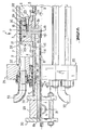
- a calibration gauge 1 essentially comprises a cylinder 2 in which can freely slide a piston 3 provided on each side with an internally hollow rod 4, 5.
- the cylinder 2 thus defines two chambers 6, 7 on either side of the piston 3.
- each hollow rod, 4, 5 respectively has an internal and axial channel 8, 9.
- the channel 8 of the rod 4 communicates permanently with the chamber 7 of the cylinder 2 through orifices 10, for example four in number, which are drilled radially in said rod 4 and are located in the vicinity of the corresponding face of the piston 3.
- the channel 9 of the hollow rod 5 which communicates permanently with the chamber 6 of the cylinder 2 through orifices 11 made radially in said rod in the vicinity of the other face of the piston 3, as can be seen in FIGS. 1 and 2.
- the end 8a of the channel 8 of the hollow rod 4 communicates with the end 9a of the channel 9 of the hollow rod 5 by a conduit 12 provided with at least one valve 13 which can be controlled manually or automatically.
- One of the hollow rods namely the rod 4 according to the example shown, is provided with a pipe or tube 14 which passes through the channel 8, which is fixed, for example screwed, at 15 to the piston 3 and which communicates with radial bores 16 formed in the piston 3 and opening into an annular groove 17 machined in the periphery of said piston.
- 18 has been shown in FIG. 2 an orifice ensuring communication between the tube 14 and the bores 16 which, according to a preferred embodiment, constitute four conduits intersecting in the center and opening into the groove 17.
- the tube 14 is equipped with a means 19 making it possible to permanently check the tightness between the chambers 6 and 7 of the cylinder 2.
- the periphery of the piston 3 is provided with a friction ring 20 axially retained by flanges 21 and flanges 22 secured to the piston 3 by means of screws 23.
- seals and seals 24 are provided between flanges 21 and cylinder 2, and also between flanges 21 and piston 3.
- the respective ends 4b and 5b of the hollow rods 4 and 5 ensure the centering of the flanges 21 on the piston 3.
- the cylinder 2 is closed at its ends by bottoms or cylinder heads 25 traversed by the hollow rods 4 and 5.
- the sealing of the rods passing through the cylinder heads 25 is essentially ensured by a sleeve or the like 26 comprising a seal 27 and a ring friction 28.
- the free end of the rods 4 and 5 is closed by a housing or the like 29 clamped between two flanges 30 and comprising an orifice 31 ensuring the communication of the end 8a of the channel 8 of the hollow rod 4 with the pipe 12 (FIG. 1 ) allowing the communication of the two hollow rods 4 and 5, and arranged parallel to the axis of the cylinder 2.
- Each cylinder head 25 has passages 32 for pipes 33 for supplying liquid. As can be seen in FIG. 2, the passages 32 are arranged tangentially to the internal periphery of the cylinder 2 to allow on the one hand the gas purges at the high points of the cylinder, and on the other hand, the complete emptying at the low points .
- a contactor integral with the end of one of the hollow rods namely the rod 4 according to the example shown.
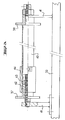
- This contactor can cooperate with two stops 37 and 38 integral with the frame 39 of the gauge according to the invention. More specifically, the stop 37 is adjustable relative to the frame 39, while the stop 38 is fixed, as will now be described in detail with reference to FIG. 3.
- the stops 37 and 38 are integral with a shaft 40 carried by supports 41 welded to the frame or chassis 39.
- the stop 38 is fixed, while the stop 37 is adjustable along the shaft 40 by being mounted on a nut 42 which can be screwed in one direction or the other on the shaft 40 and which is lockable by means of a counter nut 43.
- a ring covering the assembly which has just been described and which is thus advantageously inaccessible between two calibrations has been shown at 44 in FIG. 3.
- the distance between the stops 37 and 38 must indeed be adjusted with great precision since, as will be seen later, it is it which, during the stroke of the piston 3 in the cylinder 1, will determine the reference volume measured .
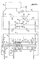
- FIG. 1 Reference will now be made again to FIG. 1 to describe the connection of the gauge 1 according to the invention to a meter 50 for liquefied gases, it being understood that such a connection is not part of the present invention but is only described for understanding the operation of the calibration gauge 1 according to the invention.
- a liquefied gas storage tank has been shown at 51 which communicates by a conduit 52, 52a provided with a pump 53, with the input of the counter 50 making it possible to measure the flow of liquefied gas delivered by the tank 51 and indicated or displayed on a volume indicator 54.
- this indicator 54 is associated an emitter 51 of electrical pulses having a resolution in relation to the required precision.
- a device 56 for counting the electrical pulses, supplied by a voltage source S, is connected on the one hand to the transmitter 55 and on the other hand to the contactor or detector 36.
- Line 52 returns to reservoir 51 via a line 57 fitted with a valve 58 for adjusting the flow rate by discharging part of the flow flow, and with a valve 59 for adjusting the pressure so to obtain a value higher than the vapor pressure of the product for the current temperature.
- the output 60 of the counter 50 is connected by a line 61 to a circuit 70 equipped with four valves 62, 63, 64 and 65.
- a suitable mechanism (not shown) ensures the simultaneous control of the four valves so that a pair of valves diagonally opposite (for example 63 and 65) are open while the other two 62 and 64 are closed.
- a pair of valves diagonally opposite for example 63 and 65
- valve system 62 to 65 By a suitable arrangement of the valve system 62 to 65, that is to say for example in the state of opening of the valves 62 and 64 and closing of the valves 63 and 65, the liquid leaving the counter 50 is sent by the conduit 34 in the chamber 7 of the cylinder 2 on the side where the piston 3 is close to the cylinder head 25, as can be seen in FIG. 1. After a few centimeters of travel, the contactor 36 is tilted by the stop 37, as it can be seen in FIG. 1, which triggers the electronic counting of the pulses which are continuously emitted by the counter. It will be noted here that the display at 54 of the volume causes the emission of electrical pulses in constant number per unit of volume displayed.
- the contactor 36 strikes the fixed stop 38, which causes the pulse counting to stop. It then suffices to open the valve 13 so that the liquid continues to circulate passing through the interior of the rods, that is to say going from one rod to the other, being of course, as we l 'saw previously that the inside of the rods is itself in permanent communication with the inside of the cylinder 2.
Landscapes
- Physics & Mathematics (AREA)
- Fluid Mechanics (AREA)
- General Physics & Mathematics (AREA)
- Filling Or Discharging Of Gas Storage Vessels (AREA)
- Measurement Of Force In General (AREA)
- Measuring Fluid Pressure (AREA)
- Pressure Sensors (AREA)
- Measurement Of Levels Of Liquids Or Fluent Solid Materials (AREA)
- Measuring Volume Flow (AREA)
- Sampling And Sample Adjustment (AREA)
- Paper (AREA)
- Electrical Discharge Machining, Electrochemical Machining, And Combined Machining (AREA)
- Amplifiers (AREA)
Claims (9)
Priority Applications (1)
| Application Number | Priority Date | Filing Date | Title |
|---|---|---|---|
| AT80401548T ATE2975T1 (de) | 1979-11-05 | 1980-10-30 | Eichvorrichtung. |
Applications Claiming Priority (2)
| Application Number | Priority Date | Filing Date | Title |
|---|---|---|---|
| FR7927210 | 1979-11-05 | ||
| FR7927210A FR2468890A1 (fr) | 1979-11-05 | 1979-11-05 | Jauge d'etalonnage |
Publications (2)
| Publication Number | Publication Date |
|---|---|
| EP0028568A1 EP0028568A1 (de) | 1981-05-13 |
| EP0028568B1 true EP0028568B1 (de) | 1983-04-06 |
Family
ID=9231291
Family Applications (1)
| Application Number | Title | Priority Date | Filing Date |
|---|---|---|---|
| EP80401548A Expired EP0028568B1 (de) | 1979-11-05 | 1980-10-30 | Eichvorrichtung |
Country Status (7)
| Country | Link |
|---|---|
| EP (1) | EP0028568B1 (de) |
| AT (1) | ATE2975T1 (de) |
| BE (1) | BE883557A (de) |
| DE (1) | DE3062643D1 (de) |
| ES (1) | ES492518A0 (de) |
| FR (1) | FR2468890A1 (de) |
| PT (1) | PT71361A (de) |
Families Citing this family (4)
| Publication number | Priority date | Publication date | Assignee | Title |
|---|---|---|---|---|
| EP0100352A1 (de) * | 1982-02-16 | 1984-02-15 | Skeltonhall Limited | Prüfvorrichtung für messgeräte |
| DE3239281C2 (de) * | 1982-10-23 | 1984-11-08 | Bopp & Reuther Gmbh, 6800 Mannheim | Prüfeinrichtung für Durchflußmesser |
| US4627267A (en) * | 1985-07-19 | 1986-12-09 | Flow Technology, Inc. | Apparatus and method for determining the flow characterstic of a volumetric flowmeter |
| CN108663099A (zh) * | 2017-04-01 | 2018-10-16 | 常州酷特仪器仪表有限公司 | 一种水表检定装置及检定方法 |
Family Cites Families (3)
| Publication number | Priority date | Publication date | Assignee | Title |
|---|---|---|---|---|
| FR1398872A (fr) * | 1964-04-01 | 1965-05-14 | Rochar Electronique | Banc d'étalonnage de mesureurs débitmétriques |
| US3673851A (en) * | 1970-08-18 | 1972-07-04 | Customline Control Products In | Meter proving system |
| US3877287A (en) * | 1972-02-27 | 1975-04-15 | Us Navy | Low flow gas or liquid calibrator |
-
1979
- 1979-11-05 FR FR7927210A patent/FR2468890A1/fr active Granted
-
1980
- 1980-05-30 BE BE0/200823A patent/BE883557A/fr not_active IP Right Cessation
- 1980-06-06 PT PT71361A patent/PT71361A/pt unknown
- 1980-06-17 ES ES492518A patent/ES492518A0/es active Granted
- 1980-10-30 DE DE8080401548T patent/DE3062643D1/de not_active Expired
- 1980-10-30 AT AT80401548T patent/ATE2975T1/de active
- 1980-10-30 EP EP80401548A patent/EP0028568B1/de not_active Expired
Also Published As
| Publication number | Publication date |
|---|---|
| FR2468890B1 (de) | 1981-11-06 |
| ES8103373A1 (es) | 1981-02-16 |
| EP0028568A1 (de) | 1981-05-13 |
| FR2468890A1 (fr) | 1981-05-08 |
| ATE2975T1 (de) | 1983-04-15 |
| ES492518A0 (es) | 1981-02-16 |
| BE883557A (fr) | 1980-09-15 |
| DE3062643D1 (en) | 1983-05-11 |
| PT71361A (fr) | 1980-07-01 |
Similar Documents
| Publication | Publication Date | Title |
|---|---|---|
| FR2514076A1 (fr) | Procede et dispositif de mesure de quantites de carburant injectees par des pompes d'injection de moteurs a combustion interne | |
| EP0028568B1 (de) | Eichvorrichtung | |
| FR2626673A1 (fr) | Procede et dispositif de mesurage de la puissance calorifique vehiculee par un courant de matiere combustible | |
| CA2052496A1 (fr) | Procede et dispositif de fourniture de gaz a un analyseur a tres haute sensibilite | |
| FR2737717A1 (fr) | Procede de recuperation de vapeur emise dans une installation de distribution de liquide | |
| FR2713300A1 (fr) | Dispositif de commande et de mesure d'écoulement. | |
| EP4388284A1 (de) | Sensor zur bestimmung eines flüssigkeitsstands für einen flugzeugtank, tank- und sensoranordnung, verfahren zur verwendung solch eines sensors | |
| EP1643230B1 (de) | Verfahren und Vorrichtung zur Kontrolle der Dichtheit einer Umhüllung enthaltend ein Druckgas | |
| EP0039293B1 (de) | Einrichtung zur präzisen Flüssigkeitsdruckmessung mit Anzeige des gemessenen Drucks | |
| WO2016038288A1 (fr) | Couplemètre hydraulique | |
| FR2572530A1 (fr) | Appareillage automatique de mesure de fractions vaporisees de corps purs et/ou melanges et des densites des phases liquide et/ou vapeur avec prelevement d'echantillons de phase vapeur | |
| EP0125992B1 (de) | Hydraulischer Stellmotor, insbesondere in Mikrobauweise, mit einer Halterung zum Anbringen von Zusatzelementen | |
| WO1980002196A1 (fr) | Procede et dispositif pour la mesure pneumatique de volume interieur de flacons | |
| FR2580396A1 (fr) | Dispositif pour indiquer et/ou mesurer les ecoulements de matiere extremement faibles | |
| EP0180844A1 (de) | Zelle zur Untersuchung einer zumindest teilweise kondensierbaren Flüssigkeit | |
| EP0076178A2 (de) | Verfahren und Vorrichtung zur Prüfung von montierten Vergasern | |
| EP2207017A1 (de) | Volumetrisches Messgerät mit zwei Kolben für eine Kraftstoff-Abgabevorrichtung | |
| EP0117207A1 (de) | Hydraulische Verteilereinrichtung | |
| CA3059193A1 (fr) | Procede pour mesurer la quantite de gaz introduite dans un reservoir et station de remplissage | |
| EP0425328A1 (de) | Verfahren und Vorrichtung zur Eichung eines Volumenzählers für beliebige Flüssigkeiten | |
| FR2734353A1 (fr) | Systeme de regles-etalons et son utilisation pour l'etalonnage d'un systeme de mesure de precision | |
| FR2677449A1 (fr) | Procede et dispositif d'etalonnage de couplemetres et couplemetre compact adapte au dispositif. | |
| FR2754342A1 (fr) | Cellule de conversion d'une pression differentielle en signal electrique | |
| EP0518758B1 (de) | Verfahren und Vorrichtung zur Kontrolle der korrekten Durchführung einer Montage | |
| FR2580803A1 (fr) | Banc de debitmetrie mobile |
Legal Events
| Date | Code | Title | Description |
|---|---|---|---|
| PUAI | Public reference made under article 153(3) epc to a published international application that has entered the european phase |
Free format text: ORIGINAL CODE: 0009012 |
|
| AK | Designated contracting states |
Designated state(s): AT CH DE GB NL |
|
| TCAT | At: translation of patent claims filed | ||
| 17P | Request for examination filed |
Effective date: 19810731 |
|
| DET | De: translation of patent claims | ||
| GRAA | (expected) grant |
Free format text: ORIGINAL CODE: 0009210 |
|
| AK | Designated contracting states |
Designated state(s): AT CH DE GB LI NL |
|
| REF | Corresponds to: |
Ref document number: 2975 Country of ref document: AT Date of ref document: 19830415 Kind code of ref document: T |
|
| REF | Corresponds to: |
Ref document number: 3062643 Country of ref document: DE Date of ref document: 19830511 |
|
| PGFP | Annual fee paid to national office [announced via postgrant information from national office to epo] |
Ref country code: AT Payment date: 19901011 Year of fee payment: 11 |
|
| PGFP | Annual fee paid to national office [announced via postgrant information from national office to epo] |
Ref country code: GB Payment date: 19901019 Year of fee payment: 11 |
|
| PGFP | Annual fee paid to national office [announced via postgrant information from national office to epo] |
Ref country code: NL Payment date: 19901031 Year of fee payment: 11 |
|
| PGFP | Annual fee paid to national office [announced via postgrant information from national office to epo] |
Ref country code: CH Payment date: 19901102 Year of fee payment: 11 |
|
| PGFP | Annual fee paid to national office [announced via postgrant information from national office to epo] |
Ref country code: DE Payment date: 19901130 Year of fee payment: 11 |
|
| PG25 | Lapsed in a contracting state [announced via postgrant information from national office to epo] |
Ref country code: GB Effective date: 19911030 Ref country code: AT Effective date: 19911030 |
|
| PG25 | Lapsed in a contracting state [announced via postgrant information from national office to epo] |
Ref country code: LI Effective date: 19911031 Ref country code: CH Effective date: 19911031 |
|
| PG25 | Lapsed in a contracting state [announced via postgrant information from national office to epo] |
Ref country code: NL Effective date: 19920501 |
|
| NLV4 | Nl: lapsed or anulled due to non-payment of the annual fee | ||
| GBPC | Gb: european patent ceased through non-payment of renewal fee | ||
| REG | Reference to a national code |
Ref country code: CH Ref legal event code: PL |
|
| PG25 | Lapsed in a contracting state [announced via postgrant information from national office to epo] |
Ref country code: DE Effective date: 19920701 |
|
| PLBE | No opposition filed within time limit |
Free format text: ORIGINAL CODE: 0009261 |
|
| STAA | Information on the status of an ep patent application or granted ep patent |
Free format text: STATUS: NO OPPOSITION FILED WITHIN TIME LIMIT |