EP0028527A1 - A system and method for sorting articles in accordance with predetermined physical characteristics - Google Patents
A system and method for sorting articles in accordance with predetermined physical characteristics Download PDFInfo
- Publication number
- EP0028527A1 EP0028527A1 EP80303917A EP80303917A EP0028527A1 EP 0028527 A1 EP0028527 A1 EP 0028527A1 EP 80303917 A EP80303917 A EP 80303917A EP 80303917 A EP80303917 A EP 80303917A EP 0028527 A1 EP0028527 A1 EP 0028527A1
- Authority
- EP
- European Patent Office
- Prior art keywords
- conveyor
- articles
- memory
- point
- points
- Prior art date
- Legal status (The legal status is an assumption and is not a legal conclusion. Google has not performed a legal analysis and makes no representation as to the accuracy of the status listed.)
- Granted
Links
Images


Classifications
-
- B—PERFORMING OPERATIONS; TRANSPORTING
- B07—SEPARATING SOLIDS FROM SOLIDS; SORTING
- B07C—POSTAL SORTING; SORTING INDIVIDUAL ARTICLES, OR BULK MATERIAL FIT TO BE SORTED PIECE-MEAL, e.g. BY PICKING
- B07C5/00—Sorting according to a characteristic or feature of the articles or material being sorted, e.g. by control effected by devices which detect or measure such characteristic or feature; Sorting by manually actuated devices, e.g. switches
- B07C5/36—Sorting apparatus characterised by the means used for distribution
- B07C5/361—Processing or control devices therefor, e.g. escort memory
-
- B—PERFORMING OPERATIONS; TRANSPORTING
- B07—SEPARATING SOLIDS FROM SOLIDS; SORTING
- B07C—POSTAL SORTING; SORTING INDIVIDUAL ARTICLES, OR BULK MATERIAL FIT TO BE SORTED PIECE-MEAL, e.g. BY PICKING
- B07C5/00—Sorting according to a characteristic or feature of the articles or material being sorted, e.g. by control effected by devices which detect or measure such characteristic or feature; Sorting by manually actuated devices, e.g. switches
- B07C5/16—Sorting according to weight
- B07C5/18—Sorting according to weight using a single stationary weighing mechanism
Definitions
- the present invention relates to the sorting of articles presented in a serial array in accordance with a predetermined physical characteristic of the articles.
- a system and method for sorting articles in accordance with a measured physical characteristic wherein a conveyor is provided which transports the articles from a point where the characteristic is measured to one of a plurality of points downstream on the conveyor each of which corresponds to a predetermined measured value or range of measured values for the physical characteristic.
- the manner in which the articles are directed to the particular discharge point involves the use of a memory segment which is assigned to each one of the discharge points. Each memory segment has a predetermined number of memory locations therein wherein the number of such locations is dependent upon the distance along the conveyor from the measuring point to the corresponding discharge point.
- the memory locations operate to receive and store digital data which is indicative of the measured physical characteristics.
- Each memory segment is associated with means for indexing each of the memory locations in sequence and means for testing the data at each indexed memory location for the presence of stored data indicative of the measured physical characteristic. Further means is provided for synchronizing the means for indexing with the movement of the transporting conveyor.
- the circuit also includes means for outputting the stored data to the discharge point corresponding to the memory segment containing the indexed memory location when digital data indicative of the measured physical characteristic is found stored therein. In this fashion articles having predetermined physical characteristics are discharged from the conveyor at predetermined discharge stations.
- a system for sorting articles in accordance with ones of a plurality of value ranges for a particular physical characteristic wherein a conveyor provides transport for articles from a first point to a plurality of second points, and wherein the physical characteristic is measured at the first point and the articles are removed from the conveyor at one of the plurality of second points corresponding to a predetermined one of the value ranges.
- The.system includes means located proximate to said first point for providing a reference output signal indicative of the position of said first point, and means located proximate to each of said plurality of second points for providing separate drop point output signals indicative of the position of separate ones of said plurality of second points.
- the system further includes means coupled to said reference and drop point output signals for storing the distance between said first point and separate ones of said second points in terms of conveyor length increments, and means for altering said stored distance when the conveyor changes length by more than a predetermined amount.
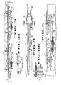
- FIG. 1 The front end and several downstream sections of a multichannel conveyor which transports articles, such as items of agricultural produce, from a source of supply to any one of a number of downstream discharge stations according to the weight of each individual item is shown in Figure 1.
- the articles of produce will hereinafter be referred to as apples, it being understood that oranges, peaches, avocados, potatoes or other types of produce also may readily be sorted according to weight by the apparatus to be hereinafter described.
- the conveyor 13 includes four conveyor channels for purposes of this description although a lesser or greater number of conveyor channels may be accommodated by the invention disclosed herein.
- the singulator 11 includes four parallel conveyors each including a long endless belt 14 and a short endless belt 16 with the upper runs of the belts being inclined to form a V-shape.
- the long and short belts are positioned adjacent to each other along one edge at the bottom of the V so that a cradle is formed to move the apples forwardly.
- One of the belts of each conveyor is driven to travel at a higher linear velocity than the other so that apples deposited thereon will be spun slightly to reduce the tendency for the apples to pile up.
- the apples reach the left end (as seen in Figure 1) of the conveyor belts they will be in substantially single file and in relatively close spacing depending upon the rate of feed from the source of supply.
- a short endless conveyor belt 17 is provided immediately downstream of each pair of belts 14, 16 to receive the apples in single file.
- Each belt 17 is comprised of a plurality of uniformly spaced cups 18.
- the extra apple will fall to one side or the other of the conveyor through an aperture 19.
- the thus dislodged apple falls upon a ramp 21 ( Figure 2) which directs it onto a retrieval conveyor 22 that reroutes the apple back to the source of supply.
- Apples carried in single file in the conveyors 17 are thereafter delivered to the channels in the multichannel conveyor 13 with which the conveyors 17 are aligned.
- Each of the channels in the conveyor 13 includes an endless array of apple receiving and holding cups 15 which pass under the discharge end of the associated conveyor 17 in a horizontally oriented carrying position as seen in Figure 1.
- the multichannel conveyor 13, the feed belts 14, 16 and the cup conveyors 17 are all driven from a common power source.
- an endless drive chain 23 is shown extending about an upper end shaft 24 for the multichannel conveyor 13, a drive shaft 26 for the cup conveyors 17 and a drive shaft 27 for the belts 14 and 16 in the singulator 11.
- the drive chain 23 is driven from the shaft 24 which, in turn, is driven by the motor (not shown) which provides the power for the multichannel conveyor 13.
- a sprocket 20 is mounted on the drive shaft 27 to provide the drive therefor through the drive chain 23.
- a separate, parallel drive shaft 25 drives the belts 16.
- the shaft 25 is driven by means of a sprocket (not shown) having a smaller diameter than that of sprocket 20 and being positioned on the opposite side of the singulator from the sprocket 20.
- the sprocket on shaft 25 is connected to shaft 27 through a drive chain (not shown) and a sprocket similar to sprocket 20 positioned on the opposite end of shaft 27 from sprocket 20.
- the belts 16 will move at a higher velocity than the belts 14, as mentioned hereinbefore.
- An idler 28 ( Figures 1 and 2) is mounted on an adjustable arm which is pivoted about a fixed pivot pin 29 and is vertically adjustable in position by means of a vertical screw adjust mechanism 31 to bear against the drive chain 23 with a greater or lesser force.
- Manipulation of the screw adjust mechanism 31 varies the effective length of the drive chain between the upper end shaft 24 on the multichannel conveyor 13 and the drive shaft 26 for the cup conveyors 17 so that the cups 18 may be adjusted to assume a proper phase relationship with the cups 15 of the multichannel conveyor.
- Slack in the drive chain 23 introduced or taken out by adjustment of the vertical screw adjust mechanism 31 is compensated for by a spring loaded idler 32 which bears against the underside of the drive chain ( Figure 2).
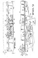
- the weight sizing apparatus including the conventional singulator 11, is supported on an underlying surface by means of a framework including left and right elongate side frame members 36 and 37, respectively, and support legs 33 as seen in Figure 2.
- the serial arrays of spaced apple-carrying cups 15 are driven along each channel in the conveyor 13 by three endless drive chains 34 ( Figures 1 and 2) arranged adjacent the side frame members 36, 37 and centrally therebetween.
- the drive chains are coupled to a drive motor (not shown) located at the downstream end of the apparatus.
- the apple-carrying cups 15 are coupled to one another across the four conveyor channels by means of a plurality of uniformly spaced rods 38, each of which extends through the leading ends of a set of four cups 15 and between the three conveyor drive chains 34 which support it.
- the conveyor drive chains are routed in a conventional manner around sprockets attached to a lower end shaft 35 ( Figure 2) and around sprockets attached to the upper end shaft 24.
- the cups 15, after travelling in the direction of arrow 12 (Figure 1) at the upper portion of the framework are rerouted back to the front end of the conveyor on a lower conveyor reach 34a ( Figure 2) located behind a longitudinal structural member 39 as seen in Figure 2.
- the cups 15 are shown in their discharge positions depending from the drive chains 34 on the return reach of the conveyor.
- a take-away conveyor 41 is shown ( Figure 2) disposed between the upper and lower reaches of the conveyor chains 34 at a discharge station downstream from the inlet end of the apparatus, and it will be appreciated that several other take-away conveyors are also present in the downstream (unshown) portion of the apparatus.
- FIG 3 an enlarged view of a weighing station on one of the lanes of conveyor 13 is there shown.
- a continuous line of spaced cups 15 is provided for each of the four channels or lanes, as previously described.
- the weighing stations, one for each channel, are at the upstream end of the conveyor 13, and each channel contains two weighing scales.
- the two scales are provided for the purpose of separating the weighing operation into weight readings in two ranges, the heavier range being measured by a high range scale 42 at the upstream end of the weighing station and the lower range being measured by a low range scale 43 at the downstream end of the weighing station.
- Each of the high and low range scales is seen to include an elongate pivot arm 44 extending along the associated conveyor channel and being pivotable downwardly about the upstream end thereof.
- the cup carrying rod 38 being connected to the conveyor drive chains 34, serves to pull the cups 15 along in each of the four channels over the pivot arms 44 of the scales.
- a guide rail 47 ( Figure 4) is seen to extend along each conveyor channel, and the high and low range scales 42, 43 are mounted along a portion of each rail as shown in Figure 3.
- the rail 47 maintains the cups 15 in their upright carrying positions by contacting a laterally projecting support pin 46 on each cup and supporting it in sliding relationship. It should be noted ( Figure 3) that at each weighing station a portion of the scale structures extend above the upper supporting level of the guide rail 47. Thus, a front end ramp 48 for each scale provides an up ramp which elevates the cup support pins 46 slightly above the level of the guide rail.
- the scale structure further includes a right side plate 49 and a left side plate 51 arranged on opposite sides of and laterally spaced from the pivot arm 44 ( Figures 4 and 5).
- the upper support surfaces of the left and right side plates 51 and 49 are at the elevation of the ramp 48 at their upstream ends ( Figure 5) but have a descending contour toward the downstream end of the scale so that each support pin 46, after passing the ramp 48, is gradually lowered in elevation and thereby caused to contact the upper edge of the associated pivot arm 44 ( at approximately the position marked by the line "x" in Figure 3).
- the pivot arm 44 has a cross pivot member 52 ( Figures 4, 5A and 5B) of cylindrical configuration fixed to the upstream end thereof.
- a transverse slot 53 ( Figure 5B) is formed in the ramp 48 so as to accept the cross pivot member 52.
- Pivot arm 44 also has a depending fin 54 attached to the pivot end thereof which fin has a hole 56 therethrough at its lower end.
- One end of a coil spring 57 is secured in the hole 56 and the other end is secured to a tension adjust rod 58.
- the rod 58 is loosely held in a housing 59 ( Figure 5) so that relative motion is permitted, and the opposite end of the tension adjust rod from that to which the spring is connected has threads 61 which accept a knurled adjust nut 62.
- Tension is imparted to the coil spring 57 by adjustment of the knurled nut 62 which shifts the position of the tension adjust rod 58 in the supporting housing 59.
- the knurled nut is locked in place after adjustment by threading a lock nut 63 tightly thereagainst. Consequently, pivot arm 44 is urged upwardly,.as seen in Figure 5, but will yield when a sufficient downwardly directed vertical force is exerted thereon.
- a channel-shaped bracket member with a flange 66 is attached to the underside of the free end of each elongate pivot arm 44 with the flange being located to contact an adjustable stop member 67 ( Figure5 )to limit the upward movement of the pivot arm.
- the stop member 67 has a threaded shank so that the stop is adjustable to a selected vertical position and may thereafter be locked in such desired vertical position by tightening the two lock nuts 68 thereon. It is desirable to adjust the stop 67 so that the elongate pivot arm 44 is urged to a position just above the surface of the guide rail 47, as seen in Figure 5, when no downward force is applied.
- the channel-shaped bracket on each of the pivot arms 44 also includes a downwardly projecting flag 69 at the forward end thereof.
- a photosensitive switch 71 includes a light source projecting a light beam across a gap to a light sensor directly below the flag 69. The photosensitive switch 71 is positioned such that when the elongate pivot arm 44 is pivoted downwardly against the tension preset in the coil spring 57, the flag 69 assumes a position to intercept the light beam and accordingly changes the electrical output of the photosensitive switch. Thus, the photosensitive switch 71 senses the pivoting of the associated pivot arm 44 and provides a signal which is indicative thereof.
- Each of the scale assemblies 42 and 43 is mounted on the associated guide rail 47 by a pair of bolts 72 ( Figures 4, 5 and 5B) which pass through the scale assemblies and engage threads in threaded holes formed in the guide rail.
- the length of the pivot arms 44 which are exposed to bear the weight transmitted through the support pins 46 for each of the cups 15 is less than one cup pitch so that there is never more than the weight of one cup and its contents on any pivot arm at any one time.
- the scale assemblies 42 and 43 in each lane are mounted on their respective guide rails 47 approximately two cup pitches apart. As seen in Figure 3, when a cup support pin 46 is received on the high range scale 42 another cup support pin is received at a corresponding point on the low range scale 43 two cup pitches away.
- load cells force sensitive transducers
- the cells would be properly positioned on the guide rails 47 to support the cups 15 in sequence as they pass in each lane.
- An output signal indicative of force applied to or weight supported by each load cell would be processed and utilized by the system to obtain the same ends as are obtained with the signal from the photosensitive switch 71 to be hereinafter discussed.
- a plurality of spaced discharge stations or drop points are located downstream from the weighing stations, the first of which is located in the area shown beneath the arrows 6-6 of Figure 2.
- one of the conveyor drive chains 34 has a magnet 73 (Figure 1) attached thereto.
- a magnetic switch 74 ( Figure 1) is attached to the guide rail 47 which the drive chain carrying the magnet 73 passes closely adjacent thereto.
- the magnetic switch 74 serves as a reference point on the conveyor frame structure for a purpose to be hereinafter described.
- Each of the downstream discharge stations also has a magnetic switch 76 (the switch for the first discharge station being shown in Figure 6) which is mounted on an outer guide rail extension 47a so that when the magnet 73 passes thereby on the adjacent conveyor drive chain 34 a switch output signal will be generated.
- the guide rail extension 47a forms a downstream extension of the guide rail 47 at the weighing stations but extends outwardly thereof so as to support the cup pins 46 at their outer ends rather than at their inner ends.
- the magnetic switches 74 and 76 serve to define the positions of the downstream discharge stations relative to the downstream end of the weighing stations in terms of cup pitch lengths (i.e., the distances between successive cups 15 carried by the conveyor chains 34) as will hereinafter be described in greater detail.
- a photosensitive switch 77 ( Figure 1) which is mounted on the inside surface of the left side frame member 36.
- a light source (not shown) is disposed on the inside surface of the left side frame member 36 below the level of the conveyor chains 34 and in alignment with switch 77.
- a light beam is directed upwardly toward the photosensitive switch 77 and is interrupted as each of the cup support rods 38 passes between the light source and the photosensitive switch.
- the output from the photosensitive switch which occurs once for each passing transverse row of cups 15, is used to confirm the completion of a weight measurement at the scales 42 and 43 for that row of cups.
- Each discharge station has a control circuit box 78 ( Figures 1 and 2) mounted on the left side frame member 36.
- An emergency "power-off" button 79 is provided on each control circuit box at each discharge station so that the apparatus may be shut down immediately from a variety of positions in the event of an emergency.
- a series of eight manually operated switches is contained in the control circuit box at each discharge station to provide means by which the address for that specific discharge station can be manually set, as will be described in greater detail hereinafter.
- a rotary solenoid drive circuit also to be hereinafter described in greater detail, is also contained in each of the discharge station control circuit boxes.
- each of the discharge station control circuit boxes is identically configured for the purpose of reducing complications in manufacture and inventory.
- Figure 6 depicts one of the channels of the first one of the discharge stations with the passing conveyor cups 15 being shown in phantom lines. That portion of the associated guide rail extension 47a which contacts the cup support pins 46 to thereby hold the cups in their normal apple carrying positions has an opening at each of the discharge stations to permit selective discharge of the cups passing thereby.
- the upstream edge of the opening is seen at 81 in Figure 6, and the downstream edge of the opening is seen at 82 (both of said edges being partially broken away and shown in phantom lines).
- a discharge gate assembly 83 is mounted to the inner surface of the guide rail extension 47a at the opening and includes a gate member 84 which is movable in the opening between the edges 81 and 82 to either bridge the opening at the level of the upper surface of the guide rail 47 (as shown in full lines in Figure 7), or to assume a position pivoted downwardly from the opening (as shown in phantom lines in Figure 7).
- a cover 86 is provided below the support surface of the guide rail extension 47a for surrounding a rotary solenoid 87 to prevent dust and debris from entering and jamming the solenoid over a prolonged period of use.
- a rotatable solenoid plate 88 is driven by the solenoid when the solenoid is energized through a pair of electrical leads 89.
- the gate member 84 has a boss 94 projecting laterally therefrom through which a pivot pin 96 extends, with the gate member being rotatable upon the pin to permit it to assume its discharging position (Figure 7).
- the pivot pin is captured in a ramp plate 97.
- the rotatable solenoid plate 88 carries thereon a cam follower pin 98 to support the gate member in its normal and discharge positions ( Figure 7).
- a pair of bolts 91 pass through the outer vertical face of the guide rail extension 47a, through spacers 92, and through the ramp plate 97 where they are engaged by a pair of nuts 93 to secure the gate assembly 83 to the conveyor frame structure at the discharge station.
- the cam follower pin 98 in its uppermost position, provides support for the gate member 84 in the normal position of the gate member spanning the opening in the guide rail extension 47a between the edges 81 and 82.
- the cam follower pin 98 is rotated downwardly to the position seen as 98a in Figure 7, and it may be seen that the gate member will fall by the force of gravity about the axis of the pivot pin 96 until a cam surface 99 on the underside of the gate member is received by the cam follower pin in position 98a.
- the passing cup support pin 46 will depart from the upper surface of the guide rail extension and traverse a down ramp 101 formed on the upper surface of the ramp plate 97. As the support pin proceeds along the down ramp 101, it may be seen that the supported cup 15 departs from its fruit carrying position and begins to pivot about the cup support rod 38 to ultimately assume a hanging discharge position.
- a deflection ramp 100 preferably having a cushioned surface thereon, is positioned so that it contacts the falling apple and deflects the apple toward the take-away conveyor 41.
- the take-away conveyor extends laterally across the apparatus, and thus is capable of receiving apples from any of the four channels of the conveyor 13.
- the cup is carried in the hanging position after it discharges the apple until it is repositioned into the horizontally oriented attitude at the front end of the conveyor adjacent upper end shaft 24; this is accomplished by extending the guide rails 47 about the shaft 24 so that they pick up the pins 46 as they are elevated vertically between shafts 35 and 24 (such means being conventional and not being shown herein).
- a solenoid 87 When a solenoid 87 has been energized, it will be deenergized after the cups have travelled through a distance substantially equiv- lent to one-half cup pitch when the support pin 46 of the discharging cup will have just cleared the end of the gate member 84 ( Figure 13).
- a contained spring in the rotary solenoid urges the cam follower pin 98 from position 89a back to its normal upper position when the solenoid is deenergized.
- the cam follower pin 98 moves along the cam surface 99 to lift the gate member until the gate member is repositioned to bridge the gap in the guide rail extension 47a between the gap edges 81 and 82.
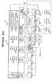
- the four channel conveyor 13 is there shown diagrammatically having the four sets of high and low range scales 42, 43 near the front end thereof. Flow on the conveyor is indicated by the feed direction arrow 12 which corresponds to the arrow 12 in Figure 1.
- the conveyor 13 has a plurality of discharge stations located therealong at each of which a take-away conveyor 41 is located as hereinbefore described.
- the magnetic switch 74 positioned adjacent the downstream end of the weighing stations is shown in Figure 8 together with the magnetic switches 76 positioned at each of the downstream discharge stations. It will be recalled that the magnetic switches 74 and 76 function in cooperation with the magnet 73 ( Figure 1) on one of the conveyor chains 34 to provide location identification for the discharge stations relative to the downstream end of the weighing station containing the scales 42 and 43 in terms of conveyor cup pitch lengths, it being recognized that these figures could vary as the conveyor chains change length due to stretching or temperature effect even though the distances between the scales and the discharge stations will remain fixed.
- the photosensitive switch 77 is shown as the"scale reference" and indicates that a line of cups 15 have just been weighed and are off of the pivot arm 44 of the downstream scale 43 in the weighing station.
- a drive chain encoder 102 is provided as shown in Figure 8 and Figures 1 and 2.
- the encoder is seen ( Figure 2) to be driven by means of a timing belt 103 which engages a gear 106 on the drive shaft for the encoder and a gear 104 on the upper end shaft 24.
- the gear ratio between the gears 104 and 106 is such as to produce a reference signal pulse for each increment of travel of the conveyor drive chains 34 equivalent to one cup pitch, such signal pulses being produced at an output indicated as 102a in Figure 8.
- the drive chain encoder 102 also produces index signals at an output 102b at a rate of 500 pulses for each pulse produced on output 102a.
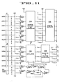
- a machine controller 107 ( Figure 8) which receives the outputs from the photosensitive switches 71 on the scales 42 and 43, the single pulse per cup pitch and the 500 pulses per cup pitch outputs from the drive chain encoder 102, the magnetic switch outputs from the magnetic switches 74 and 76, and the output from the photosensitive switch 77 indicating when a line of cups 15 has passed off the pivot arm 44 of the downstream scale 43.
- a control keyboard 108 and a cathode ray display tube 109 which is utilized for displaying the program instructions for the machine controller 107.
- Outputs from the machine controller are coupled to an interface circuit 111 and include address information, data and control signals.
- the interface circuit also receives the 500 pulse per cup pitch signal from the output 102b of the drive chain encoder 102.
- the interface circuit provides a party line output which is coupled to a plurality of the downstream discharge station control circuit boxes 78 mentioned hereinbefore.
- the party line from the interface circuit includes the address information and the data and strobe signals providing for the execution of properly addressed data at the discharge station.
- the drive chain encoder 500 pulse per cup pitch signal (line 102b)is also coupled to each of the discharge station control circuit boxes as an index signal for purposes to be hereinafter described.
- the discharge station control circuit boxes 78 are connected to the four solenoids 87 at each particular discharge station to thereby control the condition of the gate members 84 at that station in accordance with weight data obtained by the prior weight measurements which have been stored in the circuitry of the machine controller.
- the machine controller 107 is seen (in Figure 8) to be coupled to the photosensitive switch outputs from the high and low range scales 42 and 43 located in each channel of the channelized conveyor 13.
- the conveyor drive chains 34 carry the cup and the apple along the conveyor path with the support pin 46 sliding along the surface of the guide rail 47.
- the pin 46 slides up upon the ramp and continues along the upper surfaces of the right and left side plates 49 and 51 until the weight of the cup and the apple are supported on the top of the elongate pivot arm 44 (which occurs at the plane normal to the paper indicated by the letter "X" in Figure 5).
- Adjustment may be made by means of the knurled adjusting nut 62 to place enough tension in the coil spring 57 so that a predetermined range of apple weights, for example 170 to 340 grams, will cause the elongate arm 44 to pivot about the axis of the cross member 52.
- a predetermined range of apple weights for example 170 to 340 grams
- the pivot arm will be depressed against the yieldable upward force exerted on the pivot arm 44 by the coil spring 57 as soon as the support pin 46 is received upon the elongate pivot arm 44 at position "X" ( Figure 5).
- the arm 44 will not pivot downwardly against the spring tension until the support pin 46 is at the very end of the pivot arm 44. Apples between 170 grams and 340 grams will deflect the pivot arm downwardly at points between position "X" and the free end of the arm in exact proportion to the weight of the apple; that is to say, if an apple weighed 255 grams, it would deflect the arm 44 at a position half-way between position "X" and the end of the arm, etc.
- the flag 69 will interrupt the light beam in the photosensitive switch 71 and an output indicative of such interruption will be provided.
- the cup 15 proceeds to the low range scale 43 downstream therefrom wherein the tension in the coil spring 57 is adjusted differently to allow the elongate arm 44 to be rotated downwardly against the spring tension by (for example) weights in the range of 85 to 170 grams.
- the low range scale 43 functions in exactly the same fashion as the high range scale 42 producing an output from the photosensitive switch 71 when the weight transmitted to the elongate pivot arm 44 by the support pin 46 is sufficient to depress the pivot arm with the relative distance between the "scale on" position (indicated at "X") and the position where the deflection occurs directly corresponding to the weight of the apple within the indicated range.
- the signal states of the photosensitive switches 71 are brought into the machine controller 107 on eight separate lines and connected to a microprocessor or central processing unit (CPU #1)indicated at 112 in Figure 8. It may also be seen that the CPU #1 receives the 500 pulse per cup pitch index signal from the output 102b of the drive chain encoder 102. At a conveyor speed of 300 cups per minute each pulse in the 500 pulse per cup pitch train will have a period of 400 micro-seconds. During each of these pulses, which are termed index pulses, CPU #1 scans all of the scales in the high and low ranges, numbering eight in this embodiment, to find out which of the photosensitive switches 71 indicate that a corresponding pivot arm 44 is depressed. CPU 4 1 looks at each of the photosensitive switches during a scan, and if the switch output indicates that the corresponding pivot arm has been rotated downwardly, a counter in CPU #1 corresponding to that switch and a particular cup is incremented by one count.
- CPU #1 central processing unit
- the weighing station for each channel of the apparatus is arranged relative to the apply-carrying cups 15 so that cups in a given lane are in the same relative positions with respect to the scales 42 and 43 and so that three cups in each lane will need to be monitored at any given time.
- the cup As the cup moves into the weighing station area, it will be assigned a pair of counters (in the CPU #1) which will record the weight on the high and low range scales for that cup.
- the second cup will not yet be on the pivot arm.
- the third cup will just have moved off the pivot arm of scale 42, and the fourth cup will not yet have gone on the pivot arm for scale 42.
- the photosensitive switch 77 senses the support rod 38 of the first cup to cause the control circuitry to evaluate the data in the two counters corresponding to the first cup, transfer the relevant data from such counters, and reassign such counters to the fourth cup. Thereafter the index pulses are made available for incrementing of the counter for scale 42 (the"heavy” counter) for such fourth cup and for incrementing of the "light” counter for the second cup when the respective scale bars are depressed.
- the "heavy" scale count for the third cup is complete and it lies between the heavy and light scales.
- the scale reference signal from the photosensitive switch 77 is thus coupled to CPU #1 for the purpose of providing an indicator signal to the processing unit 112 that the cups are no longer on the pivot beams 44 of the scales 42 and 43 so that the machine controller is assured that the weight data obtained during the scale scan is complete.
- a read only memory (ROM) 113 is coupled to the CPU 01 for the purpose of providing permanent program instructions relative to the routine performed by the CPU in using the scale reference signals, the weight indicative signals, and the index signals.
- the weight data provided by the CPU #1 for each successive set of cups 15 is transferred to a multiport random access memory (RAM) 114 after each set of cups clears the downstream scale 43 when indicated by output from switch 77 (as previously explained) which RAM stores the data until it is called up by a central processing unit number 2 (CPU #2) seen as item 116 in Figure 8.
- CPU *2 not only reads the weight data in the multiport RAM but also has coupled thereto the single pulse per cup pitch signals from the output 102a of the drive chain encoder.
- a divide-by-fifty circuit 115 receives the 500 pulse per cup pitch signals from line 102b of the drive chain encoder therefore providing a reference signal which is ten times the frequency of the reference signal from the output 102a of the drive chain encoder.
- the drop point reference signal from the magnetic switch 74 is coupled to CPU #2 together with the outputs from each of the magnetic switches 76 at the individual downstream discharge stations.
- the keyboard 108 is also coupled into CPU #2 together with a random access memory (RAM) 117 functioning in conjunction with the keyboard to read and write the variable program instructions to CPU #2.
- RAM random access memory
- a read only memory (ROM) 118 is also coupled to CPU #2 for the purpose of providing the permanent program instructions thereto.
- CPU #2 operates to classify each of the apples carried through the weighing station by a cup 15 in each of the channels of conveyor 13 as well as to provide the appropriate drop signals for the weighed apples.
- CPU #72 also provides a drop point calibration-process and a communication scan process which latter process involves the receipt of information from the keyboard 108 in response to keyboard selections and the appropriate generation of a program in accordance therewith and the fixed program instructions from ROM 118.
- the outer conveyor drive chain 34 with the magnet 73 thereon transports the magnet past the magnetic switch 74 and each of the downstream magnetic switches 76 located at each downstream discharge station.
- the switch pulses from the magnetic switches 74 and 76 are received by CPU #2.
- the system is first placed in a "find drop points" routine which routine is initiated by receipt of the first drop point reference signal from magnetic switch 74.
- the distance from the downstream end of the weighing stations (where the switch 74 is set) to each of the downstream discharge stations or drop points (where the magnetic switches 76 are set) is thereafter measured in terms of cup pitch lengths (in a manner to be described hereinafter) in order to calibrate the apparatus - a procedure which is necessary at frequent intervals in view of chain stretch.
- the computed cup length distances from the switch 74 to each of the drop points is then stored in the RAM 117.
- a timing diagram is provided wherein the scale reference pulses 119 from the photosensitive switch 77 are shown having a repetition rate of approximately 200 milliseconds and a dwell time of approximately 8 milliseconds (the time scale not being drawn proportionately). Approximately 25 milliseconds after termination of the dwell time of a scale reference pulse a reference pulse 121 is produced which pulses occur once each cup pitch at the output 102a ( Figure 8) of the drive chain encoder 102. A train of pulses 122 from the output of the divide-by-fifty circuit 115 is seen occurring at a pulse rate which is ten times that of the reference pulses 121 and out of phase therewith (as shown).
- Both the reference pulses 121 and the reference pulses 122 have a dwell time of approximately 400 microseconds as indicated.
- the scale reference pulses 119 are used by the CPU #1 to monitor the weight-taking and transferring operations therein.
- Each of the reference pulses 122 provides an interrupt to the CPU (2 directing the processor to look into the drop reading position in an apple drop memory table and inquire as to whether any apples need to be dropped at any of the drop points at the downstream discharge stations.
- the apples carried on the multichannel conveyor 13 for which weight data has been obtained are classified in the memory table in the RAM 117 circuitry in accordance with the weight data as discussed hereinafter, and the data is located in memory such that it relates to the drop reading position in accordance with a number of pulses 122 which occur between the time the apple is classified and the time the apple reaches its drop point.
- This process of inquiry, dropping and classification is repeated for each channel in the multichannel conveyor in sequence for those cups 15 which have just been weighed and will subsequently be described in more detail.
- an apple in a lane is classified and appropriate drop commands are generated.
- the weight data On the occurrence of each of the reference pulses 121 the weight data is taken into the CPU r 2 from the multiport RAM 114. As described hereinbefore, during the period of the scale reference pulse 119 the weight data is transferred from CPU #1 to the multiport RAM 114. As a consequence, the output information from CPUSF2 which is coupled to the interface circuit 111 contains address information, weight data, a control signal and latch address information.
- FIG. 14 a flow chart is shown for the program contained in the read only memory 113 which provides direction for CPU #1.
- a system reset function is provided which occurs in either of two instances.
- a system reset is provided when power is initially turned on in the system and also when a manual switch (not shown) in the system is actuated.
- the system reset function is performed without regard for the system history and simply returns the program to a starting point.
- a subsequent initialization step is provided in the routine which gets the system ready for what is to follow.
- All random access memories in the system are cleared, certain locations within the circuitry are set to predetermined states and a data base for the system is established. Thereafter the program proceeds to an executive routine, as seen in Figure 14, which oversees two subroutines in this portion of the system, an interrupt service subroutine and a scale sub-routine.
- the interrupt service routine is normally provided with priority over the scale routine.
- An interrupt inquiry is performed for each of the index pulses from the drive chain encoder 102 at output 102b, thereby occurring 500 times for each increment of travel by the conveyor chains 34 equal to 1 cup pitch. If an interrupt command (i.e., a pulse 122) is present, a counter in CPU#l is set for scale number 1. Thereafter, the inquiry is made as to whether the scale bar for scale number 1 is depressed.
- index pulse counter for scale number 1 with the scale bar depressed is incremented by one count. Thereafter, the inquiry is made as to whether this is the last scale of the eight scales in this embodiment to be scanned. Since this is the first scale in the sequence in this instance, the answer is "no". The counter is then incremented to the next scale, which in this instance is scale number 2. The inquiry is again made as to whether the scale bar is depressed. In the event the answer to this inquiry is "no”, the inquiry is made as to whether this is the last scale in the sequence of eight described herein. Since this is the second scale in the sequence, the answer to the latter inquiry is "no", and the scan is incremented to the next scale, scale number 3 in this instance.
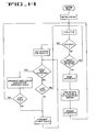
- Figure 15 shows the program flow chart for the functions contained in the read only memory 118 which are implemented by the CPU #2.
- An initial system reset function is shown which is performed when the power is first applied to the system.
- a subsequent initialization step is performed wherein all of the memories are cleared.
- Data is sent from the system to the CRT 109 ( Figure 8) where a blank apple delivery schedule, or a standard cut point table, is displayed depending on selection at the keyboard 108.
- the executive routine is entered wherein three indicators are sequentially scanned and the indicated ones of three major subroutines associated with such indicators are entered. These subroutines are (sequentially) the drop point calibration subroutine, the new weight information subroutine and the communication service subroutine.
- a fourth major subroutine, the interrupt service subroutine can be entered at any time to override the foregoing three subroutines.
- an initial inquiry is made as to whether a circuit drop point latch is set, said drop point latch being set each time a pulse is received from the switch 76 at one of the drop stations or from the drop point reference switch 74 as the magnet 73 passes thereby. If any of these switches is set it is time to enter the drop point calibration routine for the particular drop station from which the switch 76 signal was received or to initiate a calibration cycle if a switch 74 signal is received.
- the drop point latch is immediately reset after entering this subroutine so that the "yes" answer to the latch set inquiry is removed and meaningful subsequent drop point latch setting inquiries may be made.
- the inquiry is then made as to whether the drop point reference is detected, i.e., the signal provided by the drop point reference switch 74 which may be seen in Figures 1 and 8 at a point immediately downstream of the light weight scales 43. If the answer to the latter inquiry is "yes”, a new drop point distance calibration cycle is undertaken, i.e.,the calibration counter for the drop stations is cleared. Recalibration is therefore performed for every revolution of the conveyor chains 34 and is initiated by the signal from the drop point reference switch 74.
- the drop latch is set by a signal from a drop point switch 76
- a single distance count for the drop point indicated by the appropriate magnetic switch 76 which has set the drop point latch is taken (by reading the calibration counter) and stored in a drop point distance table.
- the distance counts are cumulative and are provided by the reference pulses 122 seen in Figure 10. Each distance count is taken from the calibration counter without disturbing the count therein, and the count is stored as the latest distance calibration for the drop point at which the switch 76 is actuated. A distance measurement is thereby provided which is accurate to within one tenth cup pitch.
- the encoder reference signal is provided once each cup pitch, as hereinbefore described, and may be seen as the reference pulse 121 in the timing diagram in Figure 10. If the encoder reference signal is present, the newest weights are retrieved by CPU#2 from the multiport RAM 114. The retrieved weight data is transferred from the multiport RAM to the CPU #2 about 1/6 of a cup pitch after the weight data has been transferred from CPU .#1 to the multiport RAM as hereinbefore described.
- the inquiry is made as to whether communication within the system is required, e.g., when information relative to changes in the weight ranges of apples to be dropped at the various stations or in changes in the weight counter calibrations are to be made and displayed. This amounts to an inquiry as to whether new information is available at the keyboard 108 and whether the CRT display should be altered because of inputs from the keyboard 108 ( Figure 8). A subsequent inquiry is also made as to whether data is to be sent to the CRT for display during the communication subroutine.
- An interrupt function is defined as being a system response to an input (in this case, the reception of a pulse 122) which, if the input is present, suspends whatever operation the system is undertaking and commands the system to perform a specific operation after which the system function returns to the identical point in the routine from which it departed when the suspension, or interrupt, command was received.
- Interrupt service is required in the present system as commanded by the reception by CPU #2 of each of the reference pulses 122 ( Figure 10) every one tenth cup pitch.
- the drop point distance counter which provides drop point distance calibration
- an apple drop point memory table associated with each drop point distance counter is reviewed, and those apples in proper position at the drop points are dropped.
- One apple weight (for one of the lanes) is then classified and a drop signal is inserted in the proper location in the proper drop point memory table.
- the interrupt subroutine then is finished, and the CPU#2 is returned to that part of its normal routine which it was in at the time of reception of the interrupt signal (pulse 122).
- the apples in each of the lanes will be classified and drop signals inserted in the appropriate tables during the first four pulses 122 following a pulse 121 where the new weight information is transferred from the RAM 114.
- the machine passes an article, such as an apple, received in a cup 15 from the singulator 11 over the heavy scale 42, and any resulting weight data is stored in CPU #1.
- An article such as an apple
- Two cup pitches later the same apple is passed over the light scale 43, and any resulting light scale weight data is stored in CPU #1.
- the microprocessor makes a decision relative to whether the light weight data should be thrown away or not depending on the answer to the query as to whether there is any heavy weight data stored.
- the appropriate weight data, heavy or light is then transferred to the multiport RAM 114 by actuation of the optical switch 77 (pulse 119, Figure 10) when the cup support bar 38 cuts the beam directed thereto signifying completion of the weight taking process for that apple.
- Weight data is transferred from the multiport RAM 114 to CPU #2 by the next pulse 121 ( Figure 10) from output 102a of the drive chain encoder.
- An interrupt signal is provided by each pulse 122 ( Figure 10) from the divide-by-fifty circuit 115 which initiates the interrupt subroutine incrementing the drop point calibration counter by one count (as previously explained) and also providing a look at indexed data in the drop point memory segments (to be explained hereinafter), apple dropping, memory location clearing and classification of an apple in one of the lanes.
- Each drop point on the machine of this embodiment has an address somewhere between hexadecimal 8000 and hexadecimal 803F. Since the weight classifications are programmed by the operator into the machine to provide for dropping at specific drop points for specific weight classifications, a particular apple weight when transferred from the multiport RAM 114 to CPU#2 by the occurrance of pulse 121 must be appropriately addressed.
- a 16-bit binary coded hexadecimal number within the aforementioned hexadecimal range is used for this purpose. For example, a weight programmed to be dropped at drop point number 3 will be assigned an address of 8002 hexadecimal. In binary coded form this will appear as 1000 0000 0000 0010.
- CPU #2 has a plurality of memory segments associated with each of the individual ones of the drop points on the machine.
- Figure 17 shows three memory segments corresponding to drop points 1, 2 and 3 each having 1 through m, 1 through n, and 1 through p memory locations, respectively, with the numbers "m", "n” and "p” directly corresponding to the number of interrupt pulses 122 between the signal from the switch 74 and the signal from the switch 76 for the particular drop point, e.g., "m” being the number of pulses 122 from the time that a particular apple is classified to the time that such apple is ready to be dropped at drop point 1.
- Each of the memory segments has a moving or rotating vector, or index, 11, 12 and 13 ( Figure 17) associated therewith which points to each of the stationary memory locations in sequence starting from the first and progressing through the last.
- index 11, 12 and 13
- Figure 17 the index returns to the first location and progresses in sequence through all of the memory locations once again.
- the index is advanced each 1/10 of a cup pitch by the pulse 122, and therefore a new memory location is indexed in each drop point memory segment every time the conveyor 13 advances 1/10 of one cup pitch.
- drop point calibration computation discussed previously with reference to the position of the magnetic switch 74 literally alters the length of each memory segment (the number of memory locations therein) for each drop point if the number of 1/10 cup pitches (i.e., timing pulses 122) from the position of the reference switch 74 to each drop point changes due to change in the length of conveyor chains 34. Therefore, drop point 2 memory segment, for example, may change from n locations to n+2 locations or n+1 locations depending upon the change in the number of one tenth cup pitches from the reference magnetic switch 74 to the magnetic switch 76 located at drop point two.
- the memory segment for drop point 1 must be shorter than the memory segment for drop point 2 and the segment for drop point 2 must be shorter than the segment for drop point 3 and so on.
- the index vector for that segment of memory associated with drop point 1 therefore travels the circuit of memory locations assigned thereto in a fewer number of one tenth cup pitches than does the index vector for any other drop point memory segment. While the index vectors start out at the first memory location when the machine is first turned on and they are initialized, they are out of synchronization entirely after the conveyor belt has completed the first circuit on the machine.
- index vectors sequentially address the memory locations in the memory segments assigned to a specific drop point.
- the conveyor chain 34 has advanced one tenth cup pitch an interrupt is generated by the CPU #2, the drop point distance counter is incremented by one and a process called “apple dropping" is initiated.
- the interrupt also causes all index vectors to increment one location in each drop point memory segment.
- the manner in which the aforementioned data from the memory locations is retrieved and utilized is as follows.
- the index pointers Il, 12 and 13 tell the processor CPU #2 where to "look" in the various memory segments to find data corresponding to the particular drop positions of the conveyor at that instant.
- the program instructions in ROM 118 associated with CPU #2 require, in this embodiment, that the data indexed at each memory segment be brought in sequence to an accumulator in CPU #2 during each one tenth cup pitch.
- the instructions further call for the data in the accumulator from each memory segment to be tested to see if it is non-zero.
- the instructions require that data be outputted to the address corresponding to the drop point memory segment from which it was obtained, i.e., the address of the index pointer addressing the data being retrieved.
- the CPU ⁇ 2 outputs to the interface circuitry 111 ( Figures 8 and 9) the eight bit binary number 00000001 as data, the five bits F, E, 8, 7 and 6 ( Figure 18) as the latch address and the six least significant bits of the binary coded hexadecimal ( Figure 18) as the drop point address.
- the microprocessor looks at the latest weight data received from multiport RAM 114 for lane number 1 (assuming the current interrupt pulse 122 is the first pulse 122 after the weight-transfer pulse 121).
- CPU f2 will have previously taken the new weights from the multiport RAM 114 upon the reception of a pulse 121.
- the operator has previously programmed the cut points for the apple sizing into the system via keyboard 108.
- CPU#2 investigates the cut point table and determines the class (size range) of the apple in lane 1.
- CPU #2 then investigates the delivery schedule, also programmed into the system by the operator, and determines the drop point for that class.
- the bit assigned to lane 1 for the calculated drop point (m-2 in this example if drop point one is to receive the sized apple) is then set.
- the least significant bit in the memory segment is assigned to lane 1 in this embodiment.
- the interrupt subroutine ( Figure 16) then terminates and the CPU #2 program ( Figure 15) is returned to the point where it was interrupted.
- every one tenth cup pitch the machine looks at all of the drop point index pointers and drops whatever they are pointing to that is non-zero and, while there are still apples to be classified, classifies one apple in one lane (only) and increments or sets a corresponding bit in the correct memory segment corresponding to the operator programmed drop point.
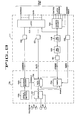
- FIG. 9 a block diagram is shown depicting the circuitry which receives the address information contained in the binary coded hexadecimal number identifying the drop point ( Figure 18) and the lane data obtained from the specific location in the memory segment which has been indexed as explained heretofore.
- Figure 9 shows the interface circuitry 111 coupled to one solenoid driver 78. All of the other solenoid drivers 78 are similarly coupled to the interface circuitry and receive the same information from the interface circuitry simultaneously.
- the solenoids 87 for the various lanes are shown in Figure 9 to be connected to a solenoid driver 137.
- the 500 pulse per cup pitch signal from output 102b of the drive chain encoder 102 is coupled to the interface circuitry 111 and is labeled "encoder index".
- the five bits from the binary coded hexadecimal 8000 address corresponding to places F, E, 8, 7 and 6 are coupled to the five "latch address" inputs to the address decoder 124.
- the address decoder also receives a "write” or timing command which is labeled "control" in Figure 9.
- a latch 123 receives the six least significant bits of the binary coded hexadecimal number illustrated in Figure 18 at six address terminals.
- the data from one memory location in one drop point memory segment is transmitted to four data terminals on the latch 123 corresponding to the four lanes of the conveyor 13. Each instance that an apple to be dropped is detected during one interrupt pulse interval, the address and data information for that drop point is sent to the interface circuitry 111, and the proper solenoid driver 78 will be actuated as will be described hereinafter.
- the five-bit latch address number simply indicates that one of the drop points along the length of the conveyor 13 is being addressed and enables the latch 123 so that the addressed solenoid driver 78 will receive the data.
- the "write" command at the control terminal at the address decoder 124 is provided with CPU/ 2 to initiate the process.
- the enabling output of decoder 124 is coupled to the latch 123 to take the address and the data into the latch and present it on six address output lines and four data output lines respectively.
- the output lines from the latch are illustrated in Figure 9 as single address and data output lines for the sake of convenience.
- a specific drop point is addressed by the six least significant bits of the binary coded hexadecimal number, and a specific lane is denoted by the data received in the 4-bit signal from CPU #2.
- the six LSB address in Figure 18 may indicate drop point 3
- the memory location number 4 ( Figure 17) indexed by pointer I 3 may indicate that the drop will be made in lane 1 at drop point 3.
- a first twelve microsecond one-shot device 128 is fired.
- a second twelve microsecond one-shot device 129 is fired.
- the output of the one-shot device 129 is coupled through a buffering inverter 131 to provide a delayed strobe signal output from the interface circuitry 111.
- the address and data lines from the latch 123 are buffered and inverted by buffering amplifiers 126 and 127 respectively before being presented at the output of the interface circuitry.
- the encoder index signal (500 pulses per cup pitch) is also buffered and inverted by buffer amplifier 132 to provide the index signal output from the interface circuitry.
- the inversion of the interface outputs are merely for the purpose of presenting the output signals therefrom in a convenient form for the solenoid driver circuits 78.
- Each of the discharge station control units includes a group of eight manually setable address switches 135 ( Figure 9).
- An address decoder 133 receives the manually set address information as well as the six lines of address information from the interface circuitry 111. When the address from the interface matches the manually selected address an enable signal is provided by the address decoder 133 to a data latch 134 and to a timer 136 which is enabled to receive the strobe signal. The leading edge of the strobe signal resets the timer 136 and removes the reset from the data latch 134.
- the data on the data lines (lane drop information) to the data latch 134 are latched into the data latch outputs and the timer begins to count 256 index counts (slightly over 1/2 cup pitch) from the encoder index pulses.
- a solenoid driver circuit 137 is energized by the output from data latch 134 so that the various solenoids 87 for each lane at the drop point will be actuated. If, for example, the solenoid driver 78 shown in Figure 9 is at discharge station three and the address and data information for the current interrupt pulse are as seen in Figures 17 and 18, then the solenoid 87 for lane 1 is actuated and the apple in lane 1 will be dropped onto the underlying takeaway conveyor 41. After the timer has received 256 encoder index pulses a timer output signal is generated and further counts are blocked. The data latch 134 is reset by the timer output signal, and the drive information at the output of the data latch 134 is removed.
- the central processing unit 11 (112) is properly represented by a * MOTOROLA MC6802L, and the central processing unit #2 (116) is properly represented by an 'INTEL 80/20-4.
- a terminal J1 in Figure 11 receives the six address inputs in the binary coded hexadecimal number of Figure 18 (identifying the proper drop station) seen as address 1 through address 6.
- Another terminal J2 has coupled thereto the four data inputs from one of the memory segments ( Figure 17) at terminals marked data 1 through data 4.
- the strobe input and the encoder index input are also shown on terminal J2.
- the address inputs are * Trade Mark coupled through buffering NOR gates Ul through U6 to one set of inputs on the address decoder 133 which is a comparator.
- Another set of inputs on the comparator is coupled to the manual address switches 135 which are preset to recognize the particular address of the drop station at which the solenoid driver control circuit 78 is located.
- the comparator 133 provides the enable output signal shown as E. It should be noted that when a specified one of the manually setable switches is set in the off condition the switch setting prevents any match in the comparator and therefore, prevents the occurrence of the enabling signal E. This switch position is used when the particular drop station is desired to be inactivated (for maintenance purposes for example).
- the data 1 through data 4 outputs are coupled through buffering NOR gates U7 through U10 ( Figure 11) to the input side of the data latch 134.
- the levels at the address and data inputs (when apples are to be dropped) are presented to each of the solenoid driver control circuits 78 as previously explained.
- the NOR gate U15 ( Figure 11) is enabled.
- NOR gate Ull produces a high output which is coupled through NOR gate U13 to produce a low output therefrom.
- the low output from U13 and the low enabling signal E cause NOR gate U15 to produce a high output to the reset terminal of the timer 136.
- the output at pin 12 of the timer 136 goes to a low state when it is reset which provides a high state signal at the output of NOR gate U18 which may be seen coupled to the reset input of the data latch 134.
- the high state signal at the reset of the data latch removes the reset therefrom and places it in condition to accept data.
- the NOR gate Ull produces a low state output which is coupled through NOR gate U13 producing a high state output therefrom.
- the high and low state outputs at the input of NOR gate U15 then provide a low state output which is coupled through NOR gate U17 to produce a high state output therefrom.
- the high output from NOR gate U17 is coupled to the data latch 134 causing the data on the data lines 1 through 4 at the outputs of the NOR gates U7-U10 to be latched into the data outputs from the data latch.
- the timer 136 then begins to count the encoder index pulses until it reaches 256 counts. At that point the output at pin 12 of the timer goes to a high state which is coupled through NOR gate U18 driving the output thereof to a low state.
- the low signal from the output of NOR gate U18 is coupled to the reset input of the data latch 134 thereby resetting the latch and removing the solenoid drive information at the latch outputs, thus allowing the solenoids 87 to be released.
- the high output at pin 12 of timer 136 is also coupled to one input of the NOR gate U14 so that the next low going encoder index pulse drives the output of U14 low.
- the output of the NOR gate U14 stays low despite the change in state on one input thereof, thereby blocking the subsequent pulses to the timer 136.
- An inverter and voltage translator 138 is shown receiving outputs from the data latch 134 to invert them and expand them to assume either a ground level or a 10 volt level (where solenoid 87 is to be activated).
- the data latch outputs are therefore only present at the output terminals Sl through S4 during that period within which 256 encoder index pulses are counted by the timer 136.
- each input S1-S4 receives either a ground signal or a 10-volt signal at pins 1 through 4 on terminal J3.
- Each of the four channels in the driver circuit 137 is the same.
- the signal development between terminal 1 on input terminal J3 and terminal 1 on output terminal J4 for the conversion of the drive signal Sl to the solenoid drive signal SlD will be discussed as examplary of the signal processing for the other channels in the driver circuit as well.
- the signal Sl assumes a 10-volt level at pin 1 of input terminal J3, it is presented to a differentiating circuit comprised of capacitor C2 and resistor R2.
- the left side ( Figure 12) of capacitor C2 has a voltage thereon which is equal in amplitude to the voltage at the upper end of the resistor R2. This level is approximately 10 volts.
- a pair of field effect power transistors Ql and Q2 function as voltage controlled current switches being primarily voltage sensitive and having a low current drain.
- a high voltage at the gate of the field effect power transistor Q2 causes conduction between the drain and source thereon. Therefore, the field effect transistor Q2 conducts at a saturation level immediately upon application of 10 volts at J3, pin 1.
- the signal which causes Q2 to initially conduct to saturation also turns on field effect power transistor Ql at a much lower level because of the lower gate voltage level provided by the biasing components Cl and Rl in the gate circuit of Ql.
- Ql therefore continuously conducts at about 0.2 amperes as long as the 10-volt signal S1 is applied to terminal 1 of the input terminal J3.
- a supply voltage VP is shown connected through input terminal J3 to each of the solenoid driver circuits.
- Each of the four rotary solenoids 87 at a drop station is connected between a respective terminal 1-4 on output terminal J4 and the supply VP.
- the diodes in the drain circuits of the field effect power transistors serve to suppress inductive transients generated by the solenoids.
- the gate members 84 at a drop station are preferably molded from a plastic material such as * Delrin or nylon so that they are low mass parts. Since the rotary solenoids 87 selected for this application are readily actuated in within 50 to 60 milliseconds at about 0.2 amperes and since a high initial current level to a solenoid is assured by the circuit described herein, the low mass gate members 84 are readily lowered (as shown in Figure 7) by the disclosed drive circuit 78 well within one-half cup pitch (100 milliseconds) at the aforementioned conveyor speed.
- a plastic material such as * Delrin or nylon
- the gate assemblies be actuated for only about one-half cup pitch at speeds of 300 to 500 cups per minute and that the gate members 84 be returned to a bridging position before the subsequent cup arrives, so that the gate may bridge the rail opening if the subsequent cup is to remain in its upright apple supporting position.
Abstract
Description
- The present invention relates to the sorting of articles presented in a serial array in accordance with a predetermined physical characteristic of the articles.
- The limitations on a system for sorting articles from a serial array of such articles presented to the system is generally dictated by the size of the memory associated with the system. Data relating to the sorting operation must be stored and retrieved before it is ultimately utilized in discharging the articles from a transporting or conveying portion of the system. Thus, the number of articles which may be handled in a given period of time and the number of sorting ranges is dictated by the size of the memory in the system.
- There are many things to remember in a more complex sorting system and very little time to put the representative data into the system memory. For a particular sorting task when a central processing unit is used to do all parts of the job, the job takes a specific amount of processing time. One of the major design questions is whether the central processing unit can accomplish all of the parts of the job in the time allotted. When the speed requirement for sorting approaches the capability limit of the sorting system, the alternatives are presented of either obtaining a higher speed central processing unit and associated circuit components or running the machine slower. The former approach provides a higher level of system expense together with a higher probability of computing errors due to the greater complexity of the circuitry while the latter alternative clearly limits the system's throughput, which is often unacceptable.
- According to one aspect of the invention described herein, there is provided a system and method for sorting articles in accordance with a measured physical characteristic wherein a conveyor is provided which transports the articles from a point where the characteristic is measured to one of a plurality of points downstream on the conveyor each of which corresponds to a predetermined measured value or range of measured values for the physical characteristic. The manner in which the articles are directed to the particular discharge point involves the use of a memory segment which is assigned to each one of the discharge points. Each memory segment has a predetermined number of memory locations therein wherein the number of such locations is dependent upon the distance along the conveyor from the measuring point to the corresponding discharge point. The memory locations operate to receive and store digital data which is indicative of the measured physical characteristics. Each memory segment is associated with means for indexing each of the memory locations in sequence and means for testing the data at each indexed memory location for the presence of stored data indicative of the measured physical characteristic. Further means is provided for synchronizing the means for indexing with the movement of the transporting conveyor. The circuit also includes means for outputting the stored data to the discharge point corresponding to the memory segment containing the indexed memory location when digital data indicative of the measured physical characteristic is found stored therein. In this fashion articles having predetermined physical characteristics are discharged from the conveyor at predetermined discharge stations.
- According to another aspect of the present invention there is provided a system for sorting articles in accordance with ones of a plurality of value ranges for a particular physical characteristic wherein a conveyor provides transport for articles from a first point to a plurality of second points, and wherein the physical characteristic is measured at the first point and the articles are removed from the conveyor at one of the plurality of second points corresponding to a predetermined one of the value ranges. The.system includes means located proximate to said first point for providing a reference output signal indicative of the position of said first point, and means located proximate to each of said plurality of second points for providing separate drop point output signals indicative of the position of separate ones of said plurality of second points.
- The system further includes means coupled to said reference and drop point output signals for storing the distance between said first point and separate ones of said second points in terms of conveyor length increments, and means for altering said stored distance when the conveyor changes length by more than a predetermined amount.
- An embodiment of the invention will now be described, by way of example only, with reference to the accompanying diagrammatic drawings, in which:
- Figure 1 is a partial plan view of the front end of a weight sizing system in accordance with the present invention;
- Figure 2 is a fragmentary side elevation of the weight sizing system of Figure 1, with portions thereof being broken away;
- Figure 3 is an enlarged section taken along line 3-3 of Figure 1 and showing weight measuring scales;
- Figure 4 is an enlarged plan view of one of the weight measuring scales;
- Figure 5 is a side elevation of the weight measuring scale shown in Figure 4;
- Figures 5A and 5B are enlarged sections taken along
lines 5A-5A and 5B-5B of Figure 4, respectively; - Figure 6 is an enlarged fragmentary plan view taken in the direction of arrows 6-6 of Figure 2 and showing one of the discharge stations and the associated gate operating mechanism;
- Figure 7 is a section taken along the line 7-7 of Figure 6 with the
magnetic switch 76 being deleted and with the discharge gate being shown in its discharge position in phantom lines; - Figure 8 is a block diagram of the electronic circuitry of the weight sizing system;
- Figure 9 is a block diagram of the interface circuit and one of the rotary solenoid driver portions of the circuitry of Figure 8;
- Figure 10 is a timing diagram showing some of the control signals in the circuitry;
- Figure 11 is an electrical schematic diagram of a portion of the circuitry in one of the rotary solenoid drivers;
- Figure 12 is an electrical schematic diagram of the specific circuitry for the driver in one of the rotary solenoid drivers;
- Figure 13 is a fragmentary section taken along a vertical longitudinal plane through the weight sizing system at one of the discharge stations and with subsequent discharging positions of one of the conveyor cups being shown in phantom lines;
- Figure 14 is a flow diagram of a program for controlling the central processing unit for the weighing operations in the sizing system;
- Figure 15 is a flow diagram of a program for controlling the central processing unit for the discharge operations in the sizing system; and
- Figure 16 is a flow diagram of a subroutine associated with the discharge operations shown in Figure 15; and
- Figure 17 is a memory diagram for data storage and retrieval in the circuitry of the system; and
- Figure 18 is a diagram of the form of some address information used in the circuitry.
- The front end and several downstream sections of a multichannel conveyor which transports articles, such as items of agricultural produce, from a source of supply to any one of a number of downstream discharge stations according to the weight of each individual item is shown in Figure 1. The articles of produce will hereinafter be referred to as apples, it being understood that oranges, peaches, avocados, potatoes or other types of produce also may readily be sorted according to weight by the apparatus to be hereinafter described. A four lane singulator, shown generally at 11 (Figures 1 and 2), which is conventional in this field, is shown mounted at the front end of a four
lane conveyor 13 with the singulator being disposed to receive apples from a source of supply such as a feed conveyor (not shown) moving in the direction of the arrow 12 (Figure 1). Theconveyor 13 includes four conveyor channels for purposes of this description although a lesser or greater number of conveyor channels may be accommodated by the invention disclosed herein. - The
singulator 11 includes four parallel conveyors each including a longendless belt 14 and a shortendless belt 16 with the upper runs of the belts being inclined to form a V-shape. The long and short belts are positioned adjacent to each other along one edge at the bottom of the V so that a cradle is formed to move the apples forwardly. One of the belts of each conveyor is driven to travel at a higher linear velocity than the other so that apples deposited thereon will be spun slightly to reduce the tendency for the apples to pile up. By the time the apples reach the left end (as seen in Figure 1) of the conveyor belts they will be in substantially single file and in relatively close spacing depending upon the rate of feed from the source of supply. A shortendless conveyor belt 17 is provided immediately downstream of each pair ofbelts belt 17 is comprised of a plurality of uniformly spacedcups 18. In the event that more than one apple is delivered to acup 18 onconveyor 17, the extra apple will fall to one side or the other of the conveyor through anaperture 19. The thus dislodged apple falls upon a ramp 21 (Figure 2) which directs it onto aretrieval conveyor 22 that reroutes the apple back to the source of supply. Apples carried in single file in theconveyors 17 are thereafter delivered to the channels in themultichannel conveyor 13 with which theconveyors 17 are aligned. Each of the channels in theconveyor 13 includes an endless array of apple receiving and holdingcups 15 which pass under the discharge end of the associatedconveyor 17 in a horizontally oriented carrying position as seen in Figure 1. - The
multichannel conveyor 13, thefeed belts cup conveyors 17 are all driven from a common power source. In Figure 2 anendless drive chain 23 is shown extending about anupper end shaft 24 for themultichannel conveyor 13, adrive shaft 26 for thecup conveyors 17 and adrive shaft 27 for thebelts singulator 11. Thedrive chain 23 is driven from theshaft 24 which, in turn, is driven by the motor (not shown) which provides the power for themultichannel conveyor 13. It should be noted that asprocket 20 is mounted on thedrive shaft 27 to provide the drive therefor through thedrive chain 23. A separate,parallel drive shaft 25 drives thebelts 16. Theshaft 25 is driven by means of a sprocket (not shown) having a smaller diameter than that ofsprocket 20 and being positioned on the opposite side of the singulator from thesprocket 20. The sprocket onshaft 25 is connected toshaft 27 through a drive chain (not shown) and a sprocket similar tosprocket 20 positioned on the opposite end ofshaft 27 fromsprocket 20. Thus, thebelts 16 will move at a higher velocity than thebelts 14, as mentioned hereinbefore. - An idler 28 (Figures 1 and 2) is mounted on an adjustable arm which is pivoted about a fixed pivot pin 29 and is vertically adjustable in position by means of a vertical screw adjust
mechanism 31 to bear against thedrive chain 23 with a greater or lesser force. Manipulation of thescrew adjust mechanism 31 varies the effective length of the drive chain between theupper end shaft 24 on themultichannel conveyor 13 and thedrive shaft 26 for thecup conveyors 17 so that thecups 18 may be adjusted to assume a proper phase relationship with thecups 15 of the multichannel conveyor. Slack in thedrive chain 23 introduced or taken out by adjustment of the vertical screw adjustmechanism 31 is compensated for by a spring loadedidler 32 which bears against the underside of the drive chain (Figure 2). Thus, an apple which is released from acup 18 in the singulator will fall into acup 15 in theconveyor 13 only when thecup 15 is in the proper position to receive the apple. - The weight sizing apparatus, including the
conventional singulator 11, is supported on an underlying surface by means of a framework including left and right elongateside frame members legs 33 as seen in Figure 2. The serial arrays of spaced apple-carryingcups 15 are driven along each channel in theconveyor 13 by three endless drive chains 34 (Figures 1 and 2) arranged adjacent theside frame members cups 15 are coupled to one another across the four conveyor channels by means of a plurality of uniformly spacedrods 38, each of which extends through the leading ends of a set of fourcups 15 and between the threeconveyor drive chains 34 which support it. The conveyor drive chains are routed in a conventional manner around sprockets attached to a lower end shaft 35 (Figure 2) and around sprockets attached to theupper end shaft 24. - The
cups 15, after travelling in the direction of arrow 12 (Figure 1) at the upper portion of the framework are rerouted back to the front end of the conveyor on alower conveyor reach 34a (Figure 2) located behind a longitudinalstructural member 39 as seen in Figure 2. Thecups 15 are shown in their discharge positions depending from thedrive chains 34 on the return reach of the conveyor. A take-awayconveyor 41 is shown (Figure 2) disposed between the upper and lower reaches of theconveyor chains 34 at a discharge station downstream from the inlet end of the apparatus, and it will be appreciated that several other take-away conveyors are also present in the downstream (unshown) portion of the apparatus. - Turning to Figure 3, an enlarged view of a weighing station on one of the lanes of
conveyor 13 is there shown. A continuous line of spacedcups 15 is provided for each of the four channels or lanes, as previously described. The weighing stations, one for each channel, are at the upstream end of theconveyor 13, and each channel contains two weighing scales. The two scales are provided for the purpose of separating the weighing operation into weight readings in two ranges, the heavier range being measured by ahigh range scale 42 at the upstream end of the weighing station and the lower range being measured by alow range scale 43 at the downstream end of the weighing station. Thus, all of the apples in one channel are passed over both the high and the low range scales 42 and 43 although only one scale will provide a reading in a manner to be described in detail hereinafter. Each of the high and low range scales is seen to include anelongate pivot arm 44 extending along the associated conveyor channel and being pivotable downwardly about the upstream end thereof. Thecup carrying rod 38, being connected to theconveyor drive chains 34, serves to pull thecups 15 along in each of the four channels over thepivot arms 44 of the scales. A guide rail 47 (Figure 4) is seen to extend along each conveyor channel, and the high and low range scales 42, 43 are mounted along a portion of each rail as shown in Figure 3. Therail 47 maintains thecups 15 in their upright carrying positions by contacting a laterally projectingsupport pin 46 on each cup and supporting it in sliding relationship. It should be noted (Figure 3) that at each weighing station a portion of the scale structures extend above the upper supporting level of theguide rail 47. Thus, afront end ramp 48 for each scale provides an up ramp which elevates the cup support pins 46 slightly above the level of the guide rail.. The scale structure further includes aright side plate 49 and aleft side plate 51 arranged on opposite sides of and laterally spaced from the pivot arm 44 (Figures 4 and 5). The upper support surfaces of the left andright side plates ramp 48 at their upstream ends (Figure 5) but have a descending contour toward the downstream end of the scale so that eachsupport pin 46, after passing theramp 48, is gradually lowered in elevation and thereby caused to contact the upper edge of the associated pivot arm 44 ( at approximately the position marked by the line "x" in Figure 3). Thepivot arm 44 has a cross pivot member 52 (Figures 4, 5A and 5B) of cylindrical configuration fixed to the upstream end thereof. A transverse slot 53 (Figure 5B) is formed in theramp 48 so as to accept thecross pivot member 52. The right and leftside plates transverse slot 53 to capture thecross pivot member 52 so that it may undergo pivoting motion within theslot 53, as best seen by reference to Figures 5A and 5B.Pivot arm 44 also has a dependingfin 54 attached to the pivot end thereof which fin has ahole 56 therethrough at its lower end. One end of acoil spring 57 is secured in thehole 56 and the other end is secured to a tension adjustrod 58. Therod 58 is loosely held in a housing 59 (Figure 5) so that relative motion is permitted, and the opposite end of the tension adjust rod from that to which the spring is connected hasthreads 61 which accept a knurled adjustnut 62. Tension is imparted to thecoil spring 57 by adjustment of theknurled nut 62 which shifts the position of the tension adjustrod 58 in the supportinghousing 59. The knurled nut is locked in place after adjustment by threading alock nut 63 tightly thereagainst. Consequently,pivot arm 44 is urged upwardly,.as seen in Figure 5, but will yield when a sufficient downwardly directed vertical force is exerted thereon. - A channel-shaped bracket member with a
flange 66 is attached to the underside of the free end of eachelongate pivot arm 44 with the flange being located to contact an adjustable stop member 67 (Figure5 )to limit the upward movement of the pivot arm. Thestop member 67 has a threaded shank so that the stop is adjustable to a selected vertical position and may thereafter be locked in such desired vertical position by tightening the twolock nuts 68 thereon. It is desirable to adjust thestop 67 so that theelongate pivot arm 44 is urged to a position just above the surface of theguide rail 47, as seen in Figure 5, when no downward force is applied. - The channel-shaped bracket on each of the
pivot arms 44 also includes a downwardly projectingflag 69 at the forward end thereof. Aphotosensitive switch 71 includes a light source projecting a light beam across a gap to a light sensor directly below theflag 69. Thephotosensitive switch 71 is positioned such that when theelongate pivot arm 44 is pivoted downwardly against the tension preset in thecoil spring 57, theflag 69 assumes a position to intercept the light beam and accordingly changes the electrical output of the photosensitive switch. Thus, thephotosensitive switch 71 senses the pivoting of the associatedpivot arm 44 and provides a signal which is indicative thereof. - Each of the
scale assemblies guide rail 47 by a pair of bolts 72 (Figures 4, 5 and 5B) which pass through the scale assemblies and engage threads in threaded holes formed in the guide rail. The length of thepivot arms 44 which are exposed to bear the weight transmitted through the support pins 46 for each of thecups 15 is less than one cup pitch so that there is never more than the weight of one cup and its contents on any pivot arm at any one time. Moreover, thescale assemblies respective guide rails 47 approximately two cup pitches apart. As seen in Figure 3, when acup support pin 46 is received on thehigh range scale 42 another cup support pin is received at a corresponding point on thelow range scale 43 two cup pitches away. - It should be recognized that load cells (force sensitive transducers) of a conventional type may be used in place of the
scale assemblies cups 15 in sequence as they pass in each lane. An output signal indicative of force applied to or weight supported by each load cell would be processed and utilized by the system to obtain the same ends as are obtained with the signal from thephotosensitive switch 71 to be hereinafter discussed. - A plurality of spaced discharge stations or drop points are located downstream from the weighing stations, the first of which is located in the area shown beneath the arrows 6-6 of Figure 2. Prior to describing the details of each of the discharge stations, it should be noted that one of the
conveyor drive chains 34 has a magnet 73 (Figure 1) attached thereto. Immediately downstream from the weighing stations a magnetic switch 74 (Figure 1) is attached to theguide rail 47 which the drive chain carrying themagnet 73 passes closely adjacent thereto. Themagnetic switch 74 serves as a reference point on the conveyor frame structure for a purpose to be hereinafter described. Each of the downstream discharge stations also has a magnetic switch 76 (the switch for the first discharge station being shown in Figure 6) which is mounted on an outerguide rail extension 47a so that when themagnet 73 passes thereby on the adjacentconveyor drive chain 34 a switch output signal will be generated. It will be noted that theguide rail extension 47a forms a downstream extension of theguide rail 47 at the weighing stations but extends outwardly thereof so as to support the cup pins 46 at their outer ends rather than at their inner ends. Themagnetic switches successive cups 15 carried by the conveyor chains 34) as will hereinafter be described in greater detail. Also located just downstream of the weighing stations is a photosensitive switch 77 (Figure 1) which is mounted on the inside surface of the leftside frame member 36. A light source (not shown) is disposed on the inside surface of the leftside frame member 36 below the level of theconveyor chains 34 and in alignment withswitch 77. A light beam is directed upwardly toward thephotosensitive switch 77 and is interrupted as each of thecup support rods 38 passes between the light source and the photosensitive switch. The output from the photosensitive switch, which occurs once for each passing transverse row ofcups 15, is used to confirm the completion of a weight measurement at thescales - Each discharge station has a control circuit box 78 (Figures 1 and 2) mounted on the left
side frame member 36. An emergency "power-off"button 79 is provided on each control circuit box at each discharge station so that the apparatus may be shut down immediately from a variety of positions in the event of an emergency. A series of eight manually operated switches is contained in the control circuit box at each discharge station to provide means by which the address for that specific discharge station can be manually set, as will be described in greater detail hereinafter. A rotary solenoid drive circuit, also to be hereinafter described in greater detail, is also contained in each of the discharge station control circuit boxes. Thus, each of the discharge station control circuit boxes is identically configured for the purpose of reducing complications in manufacture and inventory. - Figure 6 depicts one of the channels of the first one of the discharge stations with the passing conveyor cups 15 being shown in phantom lines. That portion of the associated
guide rail extension 47a which contacts the cup support pins 46 to thereby hold the cups in their normal apple carrying positions has an opening at each of the discharge stations to permit selective discharge of the cups passing thereby. The upstream edge of the opening is seen at 81 in Figure 6, and the downstream edge of the opening is seen at 82 (both of said edges being partially broken away and shown in phantom lines). Adischarge gate assembly 83 is mounted to the inner surface of theguide rail extension 47a at the opening and includes agate member 84 which is movable in the opening between theedges cover 86 is provided below the support surface of theguide rail extension 47a for surrounding arotary solenoid 87 to prevent dust and debris from entering and jamming the solenoid over a prolonged period of use. A rotatable solenoid plate 88 is driven by the solenoid when the solenoid is energized through a pair of electrical leads 89. Thegate member 84 has aboss 94 projecting laterally therefrom through which apivot pin 96 extends, with the gate member being rotatable upon the pin to permit it to assume its discharging position (Figure 7). The pivot pin is captured in aramp plate 97. The rotatable solenoid plate 88 carries thereon acam follower pin 98 to support the gate member in its normal and discharge positions (Figure 7). A pair ofbolts 91 pass through the outer vertical face of theguide rail extension 47a, throughspacers 92, and through theramp plate 97 where they are engaged by a pair ofnuts 93 to secure thegate assembly 83 to the conveyor frame structure at the discharge station. - As may be seen in full lines in Figure 7, the
cam follower pin 98, in its uppermost position, provides support for thegate member 84 in the normal position of the gate member spanning the opening in theguide rail extension 47a between theedges rotary solenoid 87 is electrically energized, thecam follower pin 98 is rotated downwardly to the position seen as 98a in Figure 7, and it may be seen that the gate member will fall by the force of gravity about the axis of thepivot pin 96 until acam surface 99 on the underside of the gate member is received by the cam follower pin in position 98a. With thegate member 84 in the lowered discharging position relative to the opening in theguide rail extension 47a, the passingcup support pin 46 will depart from the upper surface of the guide rail extension and traverse adown ramp 101 formed on the upper surface of theramp plate 97. As the support pin proceeds along thedown ramp 101, it may be seen that the supportedcup 15 departs from its fruit carrying position and begins to pivot about thecup support rod 38 to ultimately assume a hanging discharge position. - The discharging of the apple from a
cup 15 at a discharge station located along the length of theconveyor structure 13 is described more fully with reference to Figure 13 which shows the sequential pivoted positions of a cup in phantom lines. When therotary solenoid 87 is not actuated, thesupport pin 46 for each cup slides across the surface of the associatedguide rail extension 47a with the upper edge of thegate member 84 maintaining the cup in its horizontal carrying position. When thegate member 84 is pivoted downwardly into the discharge position by actuation of the correspondingrotary solenoid 87, thesupport pin 46 on the next arriving cup is shunted downwardly on thedown ramp 101 as previously described. The cup pivots in a clockwise direction as seen in Figure 13. When thesupport pin 46 passes the lower end of the down ramp, the cup is free to swing into a position where it hangs in a vertical plane from thecup support rod 38, and the apple being carried therein will tumble out. Adeflection ramp 100, preferably having a cushioned surface thereon, is positioned so that it contacts the falling apple and deflects the apple toward the take-awayconveyor 41. The take-away conveyor extends laterally across the apparatus, and thus is capable of receiving apples from any of the four channels of theconveyor 13. The cup is carried in the hanging position after it discharges the apple until it is repositioned into the horizontally oriented attitude at the front end of the conveyor adjacentupper end shaft 24; this is accomplished by extending the guide rails 47 about theshaft 24 so that they pick up thepins 46 as they are elevated vertically betweenshafts 35 and 24 (such means being conventional and not being shown herein). When asolenoid 87 has been energized, it will be deenergized after the cups have travelled through a distance substantially equiv- lent to one-half cup pitch when thesupport pin 46 of the discharging cup will have just cleared the end of the gate member 84 (Figure 13). A contained spring in the rotary solenoid urges thecam follower pin 98 from position 89a back to its normal upper position when the solenoid is deenergized. Thecam follower pin 98 moves along thecam surface 99 to lift the gate member until the gate member is repositioned to bridge the gap in theguide rail extension 47a between the gap edges 81 and 82. - The manner in which the
scales solenoids 87 are energized for actuating thevarious gate members 84 in accordance with the weights determined by the scales will not be described in conjunction with the circuitry diagram of Figure 8. The fourchannel conveyor 13 is there shown diagrammatically having the four sets of high and low range scales 42, 43 near the front end thereof. Flow on the conveyor is indicated by thefeed direction arrow 12 which corresponds to thearrow 12 in Figure 1. Theconveyor 13 has a plurality of discharge stations located therealong at each of which a take-awayconveyor 41 is located as hereinbefore described. Themagnetic switch 74 positioned adjacent the downstream end of the weighing stations is shown in Figure 8 together with themagnetic switches 76 positioned at each of the downstream discharge stations. It will be recalled that themagnetic switches conveyor chains 34 to provide location identification for the discharge stations relative to the downstream end of the weighing station containing thescales photosensitive switch 77 is shown as the"scale reference" and indicates that a line ofcups 15 have just been weighed and are off of thepivot arm 44 of thedownstream scale 43 in the weighing station. It should be noted that since corresponding points on thescales photosensitive switch 77 is positioned sufficiently close to the downstream end of the "light"scale 43 so that the "scale reference" signal is provided while there are no cups riding on the scale bars 44. Adrive chain encoder 102 is provided as shown in Figure 8 and Figures 1 and 2. The encoder is seen (Figure 2) to be driven by means of atiming belt 103 which engages agear 106 on the drive shaft for the encoder and agear 104 on theupper end shaft 24. The gear ratio between thegears conveyor drive chains 34 equivalent to one cup pitch, such signal pulses being produced at an output indicated as 102a in Figure 8. Thedrive chain encoder 102 also produces index signals at an output 102b at a rate of 500 pulses for each pulse produced onoutput 102a. - Associated with the
multichannel conveyor 13 is a machine controller 107 (Figure 8) which receives the outputs from thephotosensitive switches 71 on thescales drive chain encoder 102, the magnetic switch outputs from themagnetic switches photosensitive switch 77 indicating when a line ofcups 15 has passed off thepivot arm 44 of thedownstream scale 43. Also coupled to themachine controller 107 is acontrol keyboard 108 and a cathoderay display tube 109 which is utilized for displaying the program instructions for themachine controller 107. Outputs from the machine controller are coupled to an interface circuit 111 and include address information, data and control signals. The interface circuit also receives the 500 pulse per cup pitch signal from the output 102b of thedrive chain encoder 102. The interface circuit provides a party line output which is coupled to a plurality of the downstream discharge stationcontrol circuit boxes 78 mentioned hereinbefore. The party line from the interface circuit includes the address information and the data and strobe signals providing for the execution of properly addressed data at the discharge station. The drive chain encoder 500 pulse per cup pitch signal (line 102b)is also coupled to each of the discharge station control circuit boxes as an index signal for purposes to be hereinafter described. The discharge stationcontrol circuit boxes 78 are connected to the foursolenoids 87 at each particular discharge station to thereby control the condition of thegate members 84 at that station in accordance with weight data obtained by the prior weight measurements which have been stored in the circuitry of the machine controller. - The
machine controller 107 is seen (in Figure 8) to be coupled to the photosensitive switch outputs from the high and low range scales 42 and 43 located in each channel of the channelizedconveyor 13. When acup 15 is carrying an apple, theconveyor drive chains 34 carry the cup and the apple along the conveyor path with thesupport pin 46 sliding along the surface of theguide rail 47. Upon reaching the front ramp 48 (Figure 5) of thehigh range scale 42 thepin 46 slides up upon the ramp and continues along the upper surfaces of the right and leftside plates knurled adjusting nut 62 to place enough tension in thecoil spring 57 so that a predetermined range of apple weights, for example 170 to 340 grams, will cause theelongate arm 44 to pivot about the axis of thecross member 52. In the aforementioned example, if the apple is a 340 gram apple or greater, the pivot arm will be depressed against the yieldable upward force exerted on thepivot arm 44 by thecoil spring 57 as soon as thesupport pin 46 is received upon theelongate pivot arm 44 at position "X" (Figure 5). On the other hand, if the apple is a 170 gram apple, thearm 44 will not pivot downwardly against the spring tension until thesupport pin 46 is at the very end of thepivot arm 44. Apples between 170 grams and 340 grams will deflect the pivot arm downwardly at points between position "X" and the free end of the arm in exact proportion to the weight of the apple; that is to say, if an apple weighed 255 grams, it would deflect thearm 44 at a position half-way between position "X" and the end of the arm, etc. When thesupport pin 46 reaches a point where thearm 44 is caused to pivot downwardly, it may be seen that theflag 69 will interrupt the light beam in thephotosensitive switch 71 and an output indicative of such interruption will be provided. - If the apple is too light to actuate the
photosensitive switch 71 in thehigh range scale 42, thecup 15 proceeds to thelow range scale 43 downstream therefrom wherein the tension in thecoil spring 57 is adjusted differently to allow theelongate arm 44 to be rotated downwardly against the spring tension by (for example) weights in the range of 85 to 170 grams. Thelow range scale 43 functions in exactly the same fashion as thehigh range scale 42 producing an output from thephotosensitive switch 71 when the weight transmitted to theelongate pivot arm 44 by thesupport pin 46 is sufficient to depress the pivot arm with the relative distance between the "scale on" position (indicated at "X") and the position where the deflection occurs directly corresponding to the weight of the apple within the indicated range. - The signal states of the
photosensitive switches 71 are brought into themachine controller 107 on eight separate lines and connected to a microprocessor or central processing unit (CPU #1)indicated at 112 in Figure 8. It may also be seen that theCPU # 1 receives the 500 pulse per cup pitch index signal from the output 102b of thedrive chain encoder 102. At a conveyor speed of 300 cups per minute each pulse in the 500 pulse per cup pitch train will have a period of 400 micro-seconds. During each of these pulses, which are termed index pulses,CPU # 1 scans all of the scales in the high and low ranges, numbering eight in this embodiment, to find out which of thephotosensitive switches 71 indicate that acorresponding pivot arm 44 is depressed.CPU 4 1 looks at each of the photosensitive switches during a scan, and if the switch output indicates that the corresponding pivot arm has been rotated downwardly, a counter inCPU # 1 corresponding to that switch and a particular cup is incremented by one count. - It will be noted from Figure 3 that the weighing station for each channel of the apparatus is arranged relative to the apply-carrying
cups 15 so that cups in a given lane are in the same relative positions with respect to thescales pivot arm 44 of thedownstream scale 43, the second cup will not yet be on the pivot arm. The third cup will just have moved off the pivot arm ofscale 42, and the fourth cup will not yet have gone on the pivot arm forscale 42. It is at such time that thephotosensitive switch 77 senses thesupport rod 38 of the first cup to cause the control circuitry to evaluate the data in the two counters corresponding to the first cup, transfer the relevant data from such counters, and reassign such counters to the fourth cup. Thereafter the index pulses are made available for incrementing of the counter for scale 42 (the"heavy" counter) for such fourth cup and for incrementing of the "light" counter for the second cup when the respective scale bars are depressed. The "heavy" scale count for the third cup is complete and it lies between the heavy and light scales. When the second cup is subsequently sensed byswitch 77 after moving off the downstream end of thelight scale 43, the aforedescribed process is repeated, and thereby the two counters associated with each cup will be alternately incremented in accordance with the scale switch readings for both of the scales and the data subsequently transferred toCPU # 1. - It has been found that all eight of the scales may be scanned and all of the relevant counters may be incremented during a period of approximately 280 micro- seconds which, being less than the 400 microseconds available between index pulses, is easily sufficient.
- It will also be noted that once a
pivot arm 44 of a scale is depressed, the relevant counter will be incremented and will continue to be incremented each index pulse until thecup support pin 46 moves off of the pivot arm. The count in the counter will then be indicative of the distance travelled by the cup while the pivot arm was depressed which, in turn, is directly proportional to the weight of the apple carried by the cup. - The scale reference signal from the
photosensitive switch 77 is thus coupled toCPU # 1 for the purpose of providing an indicator signal to theprocessing unit 112 that the cups are no longer on the pivot beams 44 of thescales - The weight data provided by the
CPU # 1 for each successive set ofcups 15 is transferred to a multiport random access memory (RAM) 114 after each set of cups clears thedownstream scale 43 when indicated by output from switch 77 (as previously explained) which RAM stores the data until it is called up by a central processing unit number 2 (CPU #2) seen asitem 116 in Figure 8. CPU *2 not only reads the weight data in the multiport RAM but also has coupled thereto the single pulse per cup pitch signals from theoutput 102a of the drive chain encoder. A divide-by-fiftycircuit 115 receives the 500 pulse per cup pitch signals from line 102b of the drive chain encoder therefore providing a reference signal which is ten times the frequency of the reference signal from theoutput 102a of the drive chain encoder. The drop point reference signal from themagnetic switch 74 is coupled toCPU # 2 together with the outputs from each of themagnetic switches 76 at the individual downstream discharge stations. Thekeyboard 108 is also coupled intoCPU # 2 together with a random access memory (RAM) 117 functioning in conjunction with the keyboard to read and write the variable program instructions toCPU # 2. A read only memory (ROM) 118 is also coupled toCPU # 2 for the purpose of providing the permanent program instructions thereto. -
CPU # 2 operates to classify each of the apples carried through the weighing station by acup 15 in each of the channels ofconveyor 13 as well as to provide the appropriate drop signals for the weighed apples.CPU # 72 also provides a drop point calibration-process and a communication scan process which latter process involves the receipt of information from thekeyboard 108 in response to keyboard selections and the appropriate generation of a program in accordance therewith and the fixed program instructions fromROM 118. - When the system is first turned on and the
multichannel conveyor 13 is energized, the outerconveyor drive chain 34 with themagnet 73 thereon (seen in Figure 1) transports the magnet past themagnetic switch 74 and each of the downstreammagnetic switches 76 located at each downstream discharge station. During the first circuit of themagnet 73 around the endless conveyor path the switch pulses from themagnetic switches CPU # 2. In accordance with the instructions contained inROM 118 the system is first placed in a "find drop points" routine which routine is initiated by receipt of the first drop point reference signal frommagnetic switch 74. The distance from the downstream end of the weighing stations (where theswitch 74 is set) to each of the downstream discharge stations or drop points ( where themagnetic switches 76 are set) is thereafter measured in terms of cup pitch lengths (in a manner to be described hereinafter) in order to calibrate the apparatus - a procedure which is necessary at frequent intervals in view of chain stretch. The computed cup length distances from theswitch 74 to each of the drop points is then stored in theRAM 117. - Referring to Figure 10, a timing diagram is provided wherein the
scale reference pulses 119 from thephotosensitive switch 77 are shown having a repetition rate of approximately 200 milliseconds and a dwell time of approximately 8 milliseconds (the time scale not being drawn proportionately). Approximately 25 milliseconds after termination of the dwell time of a scale reference pulse areference pulse 121 is produced which pulses occur once each cup pitch at theoutput 102a (Figure 8) of thedrive chain encoder 102. A train ofpulses 122 from the output of the divide-by-fiftycircuit 115 is seen occurring at a pulse rate which is ten times that of thereference pulses 121 and out of phase therewith (as shown). Both thereference pulses 121 and thereference pulses 122 have a dwell time of approximately 400 microseconds as indicated. As stated hereinbefore, thescale reference pulses 119 are used by theCPU # 1 to monitor the weight-taking and transferring operations therein. Each of thereference pulses 122 provides an interrupt to the CPU (2 directing the processor to look into the drop reading position in an apple drop memory table and inquire as to whether any apples need to be dropped at any of the drop points at the downstream discharge stations. The apples carried on themultichannel conveyor 13 for which weight data has been obtained are classified in the memory table in theRAM 117 circuitry in accordance with the weight data as discussed hereinafter, and the data is located in memory such that it relates to the drop reading position in accordance with a number ofpulses 122 which occur between the time the apple is classified and the time the apple reaches its drop point. This process of inquiry, dropping and classification is repeated for each channel in the multichannel conveyor in sequence for thosecups 15 which have just been weighed and will subsequently be described in more detail. Thus, during each period of the pulses 122 (Figure 10) for the first four of such pulses following apulse 121 an apple in a lane is classified and appropriate drop commands are generated. On the occurrence of each of thereference pulses 121 the weight data is taken into theCPU r2 from themultiport RAM 114. As described hereinbefore, during the period of thescale reference pulse 119 the weight data is transferred fromCPU # 1 to themultiport RAM 114. As a consequence, the output information from CPUSF2 which is coupled to the interface circuit 111 contains address information, weight data, a control signal and latch address information. - It is useful here for the purpose of amplifying the description of the manner in which the
machine controller 107 operates to describe the programming of ROM's 113 and 118 in a preferred embodiment. Referring to Figure 14 a flow chart is shown for the program contained in the read onlymemory 113 which provides direction forCPU # 1. A system reset function is provided which occurs in either of two instances. A system reset is provided when power is initially turned on in the system and also when a manual switch (not shown) in the system is actuated. The system reset function is performed without regard for the system history and simply returns the program to a starting point. A subsequent initialization step is provided in the routine which gets the system ready for what is to follow. All random access memories in the system are cleared, certain locations within the circuitry are set to predetermined states and a data base for the system is established. Thereafter the program proceeds to an executive routine, as seen in Figure 14, which oversees two subroutines in this portion of the system, an interrupt service subroutine and a scale sub-routine. The interrupt service routine is normally provided with priority over the scale routine. An interrupt inquiry is performed for each of the index pulses from thedrive chain encoder 102 at output 102b, thereby occurring 500 times for each increment of travel by theconveyor chains 34 equal to 1 cup pitch. If an interrupt command (i.e., a pulse 122) is present, a counter in CPU#l is set forscale number 1. Thereafter, the inquiry is made as to whether the scale bar forscale number 1 is depressed. If the answer is "yes", index pulse counter forscale number 1 with the scale bar depressed is incremented by one count. Thereafter, the inquiry is made as to whether this is the last scale of the eight scales in this embodiment to be scanned. Since this is the first scale in the sequence in this instance, the answer is "no". The counter is then incremented to the next scale, which in this instance isscale number 2. The inquiry is again made as to whether the scale bar is depressed. In the event the answer to this inquiry is "no", the inquiry is made as to whether this is the last scale in the sequence of eight described herein. Since this is the second scale in the sequence, the answer to the latter inquiry is "no", and the scan is incremented to the next scale,scale number 3 in this instance. The foregoing sequence is followed for each of the scales until the eighth, or last scale, in this embodiment is coupled to its counter. If the scale bar is depressed on the eighth scale, the counter for the eighth scale is incremented by one count. The ensuring last scale inquiry is then answered "yes" and the routine is returned to the executive function. If the answer is "no" to the inquiry as to whether the scale bar is depressed, a subsequent last scale inquiry is then answered affirmatively and the routine also returns to the executive function. - In the program flow chart of Figure 14, if the interrupt inquiry is answered "no", a subsequent inquiry,- is made as to whether the scale reference is detected. The scale reference detection signal, as hereinbefore described, is provided by the
optical sensor 77 which is sensitive to the passage of therods 38 which couple thecups 15 to theconveyor chain 34 on the machine. If the scale reference detection inquiry is answered "no", the routine is returned to the executive function. If the last mentioned inquiry is answered affirmatively, the interrupt function is masked so that it will not be initiated. In essence this switches priority to the scale routine. The weights are then taken from the counters inCPU # 1 for all eight scales and are transferred to the multiportrandom access memory 114 seen in Figure 8. Thereafter the interrupt function is unmasked and the routine is returned to the executive function. The weight data transferred fromCPU # 1 to themultiport RAM 114 is thereby made available to be read byCPU# 2. - Figure 15 shows the program flow chart for the functions contained in the read only
memory 118 which are implemented by theCPU # 2. An initial system reset function is shown which is performed when the power is first applied to the system. A subsequent initialization step is performed wherein all of the memories are cleared. Data is sent from the system to the CRT 109 (Figure 8) where a blank apple delivery schedule, or a standard cut point table, is displayed depending on selection at thekeyboard 108. Thereafter, the executive routine is entered wherein three indicators are sequentially scanned and the indicated ones of three major subroutines associated with such indicators are entered. These subroutines are (sequentially) the drop point calibration subroutine, the new weight information subroutine and the communication service subroutine. A fourth major subroutine, the interrupt service subroutine, can be entered at any time to override the foregoing three subroutines. In making a decision as to whether or not to enter the first subroutine, an initial inquiry is made as to whether a circuit drop point latch is set, said drop point latch being set each time a pulse is received from theswitch 76 at one of the drop stations or from the droppoint reference switch 74 as themagnet 73 passes thereby. If any of these switches is set it is time to enter the drop point calibration routine for the particular drop station from which theswitch 76 signal was received or to initiate a calibration cycle if aswitch 74 signal is received. The drop point latch is immediately reset after entering this subroutine so that the "yes" answer to the latch set inquiry is removed and meaningful subsequent drop point latch setting inquiries may be made. The inquiry is then made as to whether the drop point reference is detected, i.e., the signal provided by the droppoint reference switch 74 which may be seen in Figures 1 and 8 at a point immediately downstream of the light weight scales 43. If the answer to the latter inquiry is "yes", a new drop point distance calibration cycle is undertaken, i.e.,the calibration counter for the drop stations is cleared. Recalibration is therefore performed for every revolution of theconveyor chains 34 and is initiated by the signal from the droppoint reference switch 74. If the answer to the drop point reference inquiry is "no", i.e., the drop latch is set by a signal from adrop point switch 76, then a single distance count for the drop point indicated by the appropriatemagnetic switch 76 which has set the drop point latch is taken (by reading the calibration counter) and stored in a drop point distance table. The distance counts are cumulative and are provided by thereference pulses 122 seen in Figure 10. Each distance count is taken from the calibration counter without disturbing the count therein, and the count is stored as the latest distance calibration for the drop point at which theswitch 76 is actuated. A distance measurement is thereby provided which is accurate to within one tenth cup pitch. - Next, the system senses whether or not the encoder reference signal is detected. The encoder reference signal is provided once each cup pitch, as hereinbefore described, and may be seen as the
reference pulse 121 in the timing diagram in Figure 10. If the encoder reference signal is present, the newest weights are retrieved byCPU# 2 from themultiport RAM 114. The retrieved weight data is transferred from the multiport RAM to theCPU # 2 about 1/6 of a cup pitch after the weight data has been transferred from CPU .#1 to the multiport RAM as hereinbefore described. - If there is no encoder reference signal detected from
output 102a of thedrive chain encoder 102 or after performing the weight taking subroutine, the inquiry is made as to whether communication within the system is required, e.g., when information relative to changes in the weight ranges of apples to be dropped at the various stations or in changes in the weight counter calibrations are to be made and displayed. This amounts to an inquiry as to whether new information is available at thekeyboard 108 and whether the CRT display should be altered because of inputs from the keyboard 108 (Figure 8). A subsequent inquiry is also made as to whether data is to be sent to the CRT for display during the communication subroutine. - An interrupt function is defined as being a system response to an input (in this case, the reception of a pulse 122) which, if the input is present, suspends whatever operation the system is undertaking and commands the system to perform a specific operation after which the system function returns to the identical point in the routine from which it departed when the suspension, or interrupt, command was received. Interrupt service is required in the present system as commanded by the reception by
CPU # 2 of each of the reference pulses 122 (Figure 10) every one tenth cup pitch. With the reception of eachpulse 122, the drop point distance counter ( which provides drop point distance calibration) is incremented by one. Thereafter, an apple drop point memory table associated with each drop point distance counter is reviewed, and those apples in proper position at the drop points are dropped. One apple weight (for one of the lanes) is then classified and a drop signal is inserted in the proper location in the proper drop point memory table. The interrupt subroutine then is finished, and theCPU# 2 is returned to that part of its normal routine which it was in at the time of reception of the interrupt signal (pulse 122). Thus, for the four lane system shown, the apples in each of the lanes will be classified and drop signals inserted in the appropriate tables during the first fourpulses 122 following apulse 121 where the new weight information is transferred from theRAM 114. - As mentioned hereinbefore classes or ranges of apple weights have already been preprogrammed by the system operator to be delivered to specific drop point locations. The description in this portion of the disclosure will relate to the classification of the apples by weight. As has been described hereinbefore there are a series of drop points along the length of the main
multi-lane conveyor 13 at which the take-awayconveyors 41 are located. These drop points may be numbered successively from the first drop point nearest the weighingscales conveyor 8 lanes wide and 64 drop points long, only a four lane machine has been shown herein. For the sake of simplification the discussion that follows will not go beyond the third drop point along the length of the machine and will deal primarily with only one lane (lane one) on the machine. - In brief review, the machine passes an article, such as an apple, received in a
cup 15 from thesingulator 11 over theheavy scale 42, and any resulting weight data is stored inCPU # 1. Two cup pitches later the same apple is passed over thelight scale 43, and any resulting light scale weight data is stored inCPU # 1. The microprocessor makes a decision relative to whether the light weight data should be thrown away or not depending on the answer to the query as to whether there is any heavy weight data stored. The appropriate weight data, heavy or light, is then transferred to themultiport RAM 114 by actuation of the optical switch 77 (pulse 119, Figure 10) when thecup support bar 38 cuts the beam directed thereto signifying completion of the weight taking process for that apple. Weight data is transferred from themultiport RAM 114 toCPU # 2 by the next pulse 121 (Figure 10) fromoutput 102a of the drive chain encoder. An interrupt signal is provided by each pulse 122 (Figure 10) from the divide-by-fiftycircuit 115 which initiates the interrupt subroutine incrementing the drop point calibration counter by one count (as previously explained) and also providing a look at indexed data in the drop point memory segments (to be explained hereinafter), apple dropping, memory location clearing and classification of an apple in one of the lanes. - Each drop point on the machine of this embodiment has an address somewhere between hexadecimal 8000 and hexadecimal 803F. Since the weight classifications are programmed by the operator into the machine to provide for dropping at specific drop points for specific weight classifications, a particular apple weight when transferred from the
multiport RAM 114 toCPU# 2 by the occurrance ofpulse 121 must be appropriately addressed. A 16-bit binary coded hexadecimal number within the aforementioned hexadecimal range is used for this purpose. For example, a weight programmed to be dropped atdrop point number 3 will be assigned an address of 8002 hexadecimal. In binary coded form this will appear as 1000 0000 0000 0010. This may be seen in Figure 18 where each of the 16 hexadecimal figures are shown above the sixteen bit spaces in which the binary code for hexadecimal 8002 is shown. The bits corresponding to hexadecimal places F, E, 8, 7 and 6 are used for address decoding as will be hereinafter explained. Addressing for reception by the correct one of thesolenoid drivers 78 is provided by the least significant six bits corresponding tohexadecimal places 0 through 5. Thus, it may be seen that any binary coded hexadecimal number from 8000 to 803F (64 decimal numbers) will be decoded by the least significant six bit, and the FE876 bit sequence will appear as binary 10000 for any number in that range. -
CPU # 2 has a plurality of memory segments associated with each of the individual ones of the drop points on the machine. Figure 17 shows three memory segments corresponding to droppoints pulses 122 between the signal from theswitch 74 and the signal from theswitch 76 for the particular drop point, e.g., "m" being the number ofpulses 122 from the time that a particular apple is classified to the time that such apple is ready to be dropped atdrop point 1. Each of the memory segments has a moving or rotating vector, or index, 11, 12 and 13 (Figure 17) associated therewith which points to each of the stationary memory locations in sequence starting from the first and progressing through the last. When the last memory location in the segment for a particular drop point is reached, the index returns to the first location and progresses in sequence through all of the memory locations once again. The index is advanced each 1/10 of a cup pitch by thepulse 122, and therefore a new memory location is indexed in each drop point memory segment every time theconveyor 13advances 1/10 of one cup pitch. The drop point calibration computation discussed previously with reference to the position of themagnetic switch 74 literally alters the length of each memory segment (the number of memory locations therein) for each drop point if the number of 1/10 cup pitches (i.e., timing pulses 122) from the position of thereference switch 74 to each drop point changes due to change in the length ofconveyor chains 34. Therefore, droppoint 2 memory segment, for example, may change from n locations to n+2 locations or n+1 locations depending upon the change in the number of one tenth cup pitches from the referencemagnetic switch 74 to themagnetic switch 76 located at drop point two. - Presuming the drop points progress numerically in the downstream direction on the machine, it should be apparent that the memory segment for
drop point 1 must be shorter than the memory segment fordrop point 2 and the segment fordrop point 2 must be shorter than the segment fordrop point 3 and so on. The index vector for that segment of memory associated withdrop point 1 therefore travels the circuit of memory locations assigned thereto in a fewer number of one tenth cup pitches than does the index vector for any other drop point memory segment. While the index vectors start out at the first memory location when the machine is first turned on and they are initialized, they are out of synchronization entirely after the conveyor belt has completed the first circuit on the machine. - The important factor to note here is that the index vectors sequentially address the memory locations in the memory segments assigned to a specific drop point. When the
conveyor chain 34 has advanced one tenth cup pitch an interrupt is generated by theCPU # 2, the drop point distance counter is incremented by one and a process called "apple dropping" is initiated. The interrupt also causes all index vectors to increment one location in each drop point memory segment. - With reference to the interrupt subroutine flow diagram for "apple dropping and classification" (Figure 16), the process initiated by this last incrementing of all of the index pointers will be followed. At this position of the
conveyor chains 34 the index pointers I1, 12 and 13 will be taken to be at memory locations m-2, n-6 and 4 respectively (Figure 17). The subroutine of Figure 16 is entered at point A in Figure 15, and all of the index pointers are incremented by one memory location.CPU# 2 then inquires as to whether the memory location m-2 for drop point one is non-zero. In this instance it is zero, i.e., no lane has an apple to be dropped (Figure 17), so the answer is "no". Next an inquiry is made as to whether this is the last drop point. The answer is "no"again. Therefore the machine goes to the next drop point, which is drop point two, and asks if the data in the memory location n-6 is non-zero. "No" is the answer. Drop point two is not the last drop point on the machine so the memory segment corresponding to drop point three is queried for non-zero data atmemory location 4. The memory is non-zero because the lane#l bit has been set as shown. Therefore, the answer to the inquiry is "yes", and the apple is dropped inlane 1 at drop point three. As the process continues through all drop point memory segments, apples are dropped in all lanes where a non-zero value exists for the memory location to which the index pointer is directed. The indexed non-zero memory bits at each drop point are cleared after the signal is sent to cause the apples to be dropped. - The manner in which the aforementioned data from the memory locations is retrieved and utilized is as follows. The index pointers Il, 12 and 13 tell the
processor CPU # 2 where to "look" in the various memory segments to find data corresponding to the particular drop positions of the conveyor at that instant. The program instructions inROM 118 associated withCPU # 2 require, in this embodiment, that the data indexed at each memory segment be brought in sequence to an accumulator inCPU # 2 during each one tenth cup pitch. The instructions further call for the data in the accumulator from each memory segment to be tested to see if it is non-zero. If the data is non-zero the instructions require that data be outputted to the address corresponding to the drop point memory segment from which it was obtained, i.e., the address of the index pointer addressing the data being retrieved. For example, with a non-zero determination such as will be made with theindex pointer 13 positioned as shown in Figure 17 for the memory segment assigned to drop point three, the CPU§2 outputs to the interface circuitry 111 (Figures 8 and 9) the eight bit binary number 00000001 as data, the five bits F, E, 8, 7 and 6 (Figure 18) as the latch address and the six least significant bits of the binary coded hexadecimal (Figure 18) as the drop point address. - After the last drop point memory location is reviewed by
CPU # 2, the microprocessor looks at the latest weight data received frommultiport RAM 114 for lane number 1 (assuming the current interruptpulse 122 is thefirst pulse 122 after the weight-transfer pulse 121). CPU f2 will have previously taken the new weights from themultiport RAM 114 upon the reception of apulse 121. The operator has previously programmed the cut points for the apple sizing into the system viakeyboard 108.CPU# 2 investigates the cut point table and determines the class (size range) of the apple inlane 1.CPU # 2 then investigates the delivery schedule, also programmed into the system by the operator, and determines the drop point for that class. The bit assigned tolane 1 for the calculated drop point (m-2 in this example if drop point one is to receive the sized apple) is then set. The least significant bit in the memory segment is assigned tolane 1 in this embodiment. The interrupt subroutine (Figure 16) then terminates and theCPU # 2 program (Figure 15) is returned to the point where it was interrupted. - The flow diagram of Figure 16 is repeated at the next interrupt
pulse 122 wherein each of the memory segments is first interrogated to determine if there are apples to be dropped. Then, the new weight for lane number two is classified in the correct memory location in the correct drop point memory segment, and, since the index pointers (Il, I2, etc.) have now been shifted by one memory location it will be necessary to place the "one" bit one memory location back in the segment in order to assume that the apple inlane 2 will be dropped at the proper time. For example, if the apple inlane 2 were to be dropped at drop point three, the bit inlane 2 ofmemory location 4 would be set even though theindex pointer 13 would then be pointing atmemory location 5 since (obviously) both the apples inlanes next pulse 121 is received to place new weight data inCPU # 2. In other words, every one tenth cup pitch the machine looks at all of the drop point index pointers and drops whatever they are pointing to that is non-zero and, while there are still apples to be classified, classifies one apple in one lane (only) and increments or sets a corresponding bit in the correct memory segment corresponding to the operator programmed drop point. - With reference to Figure 9 a block diagram is shown depicting the circuitry which receives the address information contained in the binary coded hexadecimal number identifying the drop point (Figure 18) and the lane data obtained from the specific location in the memory segment which has been indexed as explained heretofore. Figure 9 shows the interface circuitry 111 coupled to one
solenoid driver 78. All of theother solenoid drivers 78 are similarly coupled to the interface circuitry and receive the same information from the interface circuitry simultaneously. Thesolenoids 87 for the various lanes are shown in Figure 9 to be connected to asolenoid driver 137. The 500 pulse per cup pitch signal from output 102b of thedrive chain encoder 102 is coupled to the interface circuitry 111 and is labeled "encoder index". The five bits from the binary coded hexadecimal 8000 address corresponding to places F, E, 8, 7 and 6 are coupled to the five "latch address" inputs to theaddress decoder 124. The address decoder also receives a "write" or timing command which is labeled "control" in Figure 9. Alatch 123 receives the six least significant bits of the binary coded hexadecimal number illustrated in Figure 18 at six address terminals. The data from one memory location in one drop point memory segment is transmitted to four data terminals on thelatch 123 corresponding to the four lanes of theconveyor 13. Each instance that an apple to be dropped is detected during one interrupt pulse interval, the address and data information for that drop point is sent to the interface circuitry 111, and theproper solenoid driver 78 will be actuated as will be described hereinafter. - The five-bit latch address number simply indicates that one of the drop points along the length of the
conveyor 13 is being addressed and enables thelatch 123 so that the addressedsolenoid driver 78 will receive the data. The "write" command at the control terminal at theaddress decoder 124 is provided with CPU/ 2 to initiate the process. The enabling output ofdecoder 124 is coupled to thelatch 123 to take the address and the data into the latch and present it on six address output lines and four data output lines respectively. The output lines from the latch are illustrated in Figure 9 as single address and data output lines for the sake of convenience. Thus, a specific drop point is addressed by the six least significant bits of the binary coded hexadecimal number, and a specific lane is denoted by the data received in the 4-bit signal fromCPU # 2. By way of example, the six LSB address in Figure 18 may indicatedrop point 3, and the memory location number 4 (Figure 17) indexed by pointer I3 may indicate that the drop will be made inlane 1 atdrop point 3. - When the enable signal is provided at the output of the
address decoder 124 by virtue of a proper latch address and a "write" command fromCPU # 2, a first twelve microsecond one-shot device 128 is fired. On recovery of the one-shot device 128, a second twelve microsecond one-shot device 129 is fired. The output of the one-shot device 129 is coupled through abuffering inverter 131 to provide a delayed strobe signal output from the interface circuitry 111. The address and data lines from thelatch 123 are buffered and inverted by bufferingamplifiers buffer amplifier 132 to provide the index signal output from the interface circuitry. The inversion of the interface outputs are merely for the purpose of presenting the output signals therefrom in a convenient form for thesolenoid driver circuits 78. - As mentioned hereinbefore all of the downstream discharge station solenoid driver controls 78 receive the address, data, strobe and 500 pulse per cup pitch encoder index pulses simultaneously. Each of the discharge station control units includes a group of eight manually setable address switches 135 (Figure 9). An
address decoder 133 receives the manually set address information as well as the six lines of address information from the interface circuitry 111. When the address from the interface matches the manually selected address an enable signal is provided by theaddress decoder 133 to adata latch 134 and to atimer 136 which is enabled to receive the strobe signal. The leading edge of the strobe signal resets thetimer 136 and removes the reset from thedata latch 134. On the trailing edge of the strobe signal the data on the data lines (lane drop information) to the data latch 134 are latched into the data latch outputs and the timer begins to count 256 index counts (slightly over 1/2 cup pitch) from the encoder index pulses. Asolenoid driver circuit 137 is energized by the output from data latch 134 so that thevarious solenoids 87 for each lane at the drop point will be actuated. If, for example, thesolenoid driver 78 shown in Figure 9 is at discharge station three and the address and data information for the current interrupt pulse are as seen in Figures 17 and 18, then thesolenoid 87 forlane 1 is actuated and the apple inlane 1 will be dropped onto theunderlying takeaway conveyor 41. After the timer has received 256 encoder index pulses a timer output signal is generated and further counts are blocked. The data latch 134 is reset by the timer output signal, and the drive information at the output of the data latch 134 is removed. - The aforesaid components in the control portion of the system disclosed herein are readily commercially available and will be recognizable by those skilled in this art. The central processing unit 11 (112) is properly represented by a *MOTOROLA MC6802L, and the central processing unit #2 (116) is properly represented by an 'INTEL 80/20-4.
- The details of one of the rotary solenoid
driver control circuits 78 described generally hereinbefore may be seen by reference to Figures 11 and 12 where signal inversion is ignored to enhance clarity. A terminal J1 in Figure 11 receives the six address inputs in the binary coded hexadecimal number of Figure 18 (identifying the proper drop station) seen asaddress 1 throughaddress 6. Another terminal J2 has coupled thereto the four data inputs from one of the memory segments (Figure 17) at terminals markeddata 1 throughdata 4. The strobe input and the encoder index input are also shown on terminal J2. The address inputs are * Trade Mark coupled through buffering NOR gates Ul through U6 to one set of inputs on theaddress decoder 133 which is a comparator. Another set of inputs on the comparator is coupled to the manual address switches 135 which are preset to recognize the particular address of the drop station at which the solenoiddriver control circuit 78 is located. When an address is presented through the NOR gates U1-U6 which matches the preset address, thecomparator 133 provides the enable output signal shown as E. It should be noted that when a specified one of the manually setable switches is set in the off condition the switch setting prevents any match in the comparator and therefore, prevents the occurrence of the enabling signal E. This switch position is used when the particular drop station is desired to be inactivated (for maintenance purposes for example). - The
data 1 throughdata 4 outputs are coupled through buffering NOR gates U7 through U10 (Figure 11) to the input side of thedata latch 134. The levels at the address and data inputs (when apples are to be dropped) are presented to each of the solenoiddriver control circuits 78 as previously explained. When an address match is obtained and an enabling signal is provided from thecomparator 133, the NOR gate U15 (Figure 11) is enabled. Thus, when the low going leading edge of the strobe signal arrives at terminal J2,pin 9, NOR gate Ull produces a high output which is coupled through NOR gate U13 to produce a low output therefrom. The low output from U13 and the low enabling signal E cause NOR gate U15 to produce a high output to the reset terminal of thetimer 136. The output atpin 12 of thetimer 136 goes to a low state when it is reset which provides a high state signal at the output of NOR gate U18 which may be seen coupled to the reset input of thedata latch 134. The high state signal at the reset of the data latch removes the reset therefrom and places it in condition to accept data. When the trailing (rising) edge of the strobe signal occurs, the NOR gate Ull produces a low state output which is coupled through NOR gate U13 producing a high state output therefrom. The high and low state outputs at the input of NOR gate U15 then provide a low state output which is coupled through NOR gate U17 to produce a high state output therefrom. The high output from NOR gate U17 is coupled to the data latch 134 causing the data on thedata lines 1 through 4 at the outputs of the NOR gates U7-U10 to be latched into the data outputs from the data latch. Thetimer 136 then begins to count the encoder index pulses until it reaches 256 counts. At that point the output atpin 12 of the timer goes to a high state which is coupled through NOR gate U18 driving the output thereof to a low state. The low signal from the output of NOR gate U18 is coupled to the reset input of the data latch 134 thereby resetting the latch and removing the solenoid drive information at the latch outputs, thus allowing thesolenoids 87 to be released. The high output atpin 12 oftimer 136 is also coupled to one input of the NOR gate U14 so that the next low going encoder index pulse drives the output of U14 low. The output of the NOR gate U14 stays low despite the change in state on one input thereof, thereby blocking the subsequent pulses to thetimer 136. An inverter andvoltage translator 138 is shown receiving outputs from the data latch 134 to invert them and expand them to assume either a ground level or a 10 volt level (wheresolenoid 87 is to be activated). The data latch outputs are therefore only present at the output terminals Sl through S4 during that period within which 256 encoder index pulses are counted by thetimer 136. - In Figure 12 the
driver circuit 137 for the foursolenoids 87 located at each drop station is shown. As pointed out, each input S1-S4 receives either a ground signal or a 10-volt signal atpins 1 through 4 on terminal J3. Each of the four channels in thedriver circuit 137 is the same. The signal development betweenterminal 1 on input terminal J3 and terminal 1 on output terminal J4 for the conversion of the drive signal Sl to the solenoid drive signal SlD will be discussed as examplary of the signal processing for the other channels in the driver circuit as well. When the signal Sl assumes a 10-volt level atpin 1 of input terminal J3, it is presented to a differentiating circuit comprised of capacitor C2 and resistor R2. At the positive edge of the 10-volt signal the left side (Figure 12) of capacitor C2 has a voltage thereon which is equal in amplitude to the voltage at the upper end of the resistor R2. This level is approximately 10 volts. As capacitor C2 charges, the current through resistor R2 diminishes and the voltage across the resistor R2 decreases. A pair of field effect power transistors Ql and Q2 function as voltage controlled current switches being primarily voltage sensitive and having a low current drain. A high voltage at the gate of the field effect power transistor Q2 causes conduction between the drain and source thereon. Therefore, the field effect transistor Q2 conducts at a saturation level immediately upon application of 10 volts at J3,pin 1. Q2 conducts over one ampere, in this instance, until the voltage across resistor R2 falls to a level which turns Q2 off. The current is drawn through therotary solenoid 87 which is connected to pin 1 of the output terminal J4. The R2-C2 combination is such that this high current conduction level through the solenoid coil persists for about 30 milliseconds until capacitor C2 charges and transistor Q2 is turned off when the gate voltage falls below a certain level. - The signal which causes Q2 to initially conduct to saturation also turns on field effect power transistor Ql at a much lower level because of the lower gate voltage level provided by the biasing components Cl and Rl in the gate circuit of Ql. Ql therefore continuously conducts at about 0.2 amperes as long as the 10-volt signal S1 is applied to
terminal 1 of the input terminal J3. A supply voltage VP is shown connected through input terminal J3 to each of the solenoid driver circuits. Each of the fourrotary solenoids 87 at a drop station is connected between a respective terminal 1-4 on output terminal J4 and the supply VP. The diodes in the drain circuits of the field effect power transistors serve to suppress inductive transients generated by the solenoids. - The
gate members 84 at a drop station (Figure 13) are preferably molded from a plastic material such as * Delrin or nylon so that they are low mass parts. Since therotary solenoids 87 selected for this application are readily actuated in within 50 to 60 milliseconds at about 0.2 amperes and since a high initial current level to a solenoid is assured by the circuit described herein, the lowmass gate members 84 are readily lowered (as shown in Figure 7) by the discloseddrive circuit 78 well within one-half cup pitch (100 milliseconds) at the aforementioned conveyor speed. It is essential to the high speed weight sizing performed by the system described herein that the gate assemblies be actuated for only about one-half cup pitch at speeds of 300 to 500 cups per minute and that thegate members 84 be returned to a bridging position before the subsequent cup arrives, so that the gate may bridge the rail opening if the subsequent cup is to remain in its upright apple supporting position. - The system particularly described sorts in an accurate and rapid manner a large number of articles presented in serial array. *Trade Mark
Claims (10)
Applications Claiming Priority (2)
| Application Number | Priority Date | Filing Date | Title |
|---|---|---|---|
| US91322 | 1979-11-05 | ||
| US06/091,322 US4299326A (en) | 1979-11-05 | 1979-11-05 | Weight sorting memory circuit |
Publications (2)
| Publication Number | Publication Date |
|---|---|
| EP0028527A1 true EP0028527A1 (en) | 1981-05-13 |
| EP0028527B1 EP0028527B1 (en) | 1984-05-30 |
Family
ID=22227187
Family Applications (1)
| Application Number | Title | Priority Date | Filing Date |
|---|---|---|---|
| EP80303917A Expired EP0028527B1 (en) | 1979-11-05 | 1980-11-04 | A system and method for sorting articles in accordance with predetermined physical characteristics |
Country Status (4)
| Country | Link |
|---|---|
| US (1) | US4299326A (en) |
| EP (1) | EP0028527B1 (en) |
| JP (1) | JPS5681172A (en) |
| ES (1) | ES496554A0 (en) |
Cited By (1)
| Publication number | Priority date | Publication date | Assignee | Title |
|---|---|---|---|---|
| EP0150538A2 (en) * | 1984-01-27 | 1985-08-07 | Administratie- en Automatiseringscentrum Vulcaan B.V. | Device and method for subjecting objects to a treatment in treatment stations allocated to them |
Families Citing this family (17)
| Publication number | Priority date | Publication date | Assignee | Title |
|---|---|---|---|---|
| JPS5697582A (en) * | 1980-01-07 | 1981-08-06 | Iseki Agricult Mach | Automatic weight selector |
| NL182940C (en) * | 1980-03-31 | 1988-06-16 | Greefs Wagen Carrosserie | DEVICE FOR SORTING PRODUCTS SUCH AS FRUITS. |
| SE446421B (en) * | 1980-06-13 | 1986-09-15 | Stora Kopparbergs Bergslags Ab | SET TO REPLACE CULTIVATION UNITS IN ELASTIC POTS AND DEVICE FOR IMPLEMENTATION OF THE SET |
| US4558212A (en) * | 1983-01-17 | 1985-12-10 | Can And Bottle Systems, Inc. | Container redemption method and apparatus |
| US4542808A (en) * | 1983-06-30 | 1985-09-24 | House Of Lloyd, Inc. | Order filling system |
| JPS6061461A (en) * | 1983-09-14 | 1985-04-09 | Toshiba Corp | Paper sheet accumulation control system |
| JPS62184591A (en) * | 1986-02-10 | 1987-08-12 | オムロン株式会社 | Automatic cash transaction processor |
| US4852029A (en) * | 1987-06-17 | 1989-07-25 | Accu-Tech Incorporated | Automated material classification apparatus and method |
| US5497887A (en) * | 1988-03-15 | 1996-03-12 | Autoline, Inc. | Method and apparatus for handling objects |
| US5244100A (en) * | 1991-04-18 | 1993-09-14 | Regier Robert D | Apparatus and method for sorting objects |
| US5985214A (en) * | 1997-05-16 | 1999-11-16 | Aurora Biosciences Corporation | Systems and methods for rapidly identifying useful chemicals in liquid samples |
| ES2282188T3 (en) * | 2000-09-14 | 2007-10-16 | De Greef's Wagen-, Carrosserie- En Machinebouw B.V. | APPARATUS AND METHOD TO TRANSPORT AND / OR TRANSFER FRUITS. |
| JP4331968B2 (en) * | 2002-05-02 | 2009-09-16 | エフ ピー エス フーヅ プロセッシング システムス ベスロテン フェンノートシャップ | Method and system for automatically sorting and packaging articles |
| US8346388B1 (en) * | 2007-12-15 | 2013-01-01 | Jared Michael Tritz | System and method for automated tactile sorting |
| CN103646251B (en) * | 2013-09-14 | 2017-05-17 | 江南大学 | Apple postharvest field classification detection method and system based on embedded technology |
| CN104368537A (en) * | 2014-11-06 | 2015-02-25 | 江苏华东锂电技术研究院有限公司 | Automatic weighing and grading equipment for battery pole pieces |
| EP4298901A1 (en) * | 2021-03-29 | 2024-01-03 | Nabel Co., Ltd. | Chicken egg sorting device, and method of using information obtainable from weighing unit |
Citations (5)
| Publication number | Priority date | Publication date | Assignee | Title |
|---|---|---|---|---|
| US3259240A (en) * | 1963-09-30 | 1966-07-05 | Paul J Schneider | Electrical command storage and distribution system |
| US3616901A (en) * | 1970-03-23 | 1971-11-02 | Industrial Nucleonics Corp | Article-classifying system and method |
| GB1394348A (en) * | 1973-07-26 | 1975-05-14 | Lind L F | Loading apparatus |
| US3930995A (en) * | 1974-08-19 | 1976-01-06 | Sunkist Growers, Inc. | Grade distributing apparatus |
| US4106628A (en) * | 1976-02-20 | 1978-08-15 | Warkentin Aaron J | Sorter for fruit and the like |
Family Cites Families (10)
| Publication number | Priority date | Publication date | Assignee | Title |
|---|---|---|---|---|
| US2666536A (en) * | 1950-02-11 | 1954-01-19 | Plywood Res Foundation | Sorter control device |
| US2601915A (en) * | 1950-08-21 | 1952-07-01 | Standard Conveyor Co | Timing mechanism and control for conveyers |
| US2895274A (en) * | 1953-12-28 | 1959-07-21 | Fmc Corp | Machine for handling eggs |
| US3460673A (en) * | 1967-06-19 | 1969-08-12 | Recognition Equipment Inc | Document sorting apparatus |
| US3640384A (en) * | 1969-07-10 | 1972-02-08 | Hi Speed Checkweigher Co | Apparatus for weight-classifying odd-shaped articles |
| US3627127A (en) * | 1969-12-09 | 1971-12-14 | Scott Cunningham Whiteford | Sorting apparatus |
| JPS5521682B2 (en) * | 1973-10-29 | 1980-06-11 | ||
| US3898435A (en) * | 1974-03-11 | 1975-08-05 | Fmc Corp | Memory device for an egg grading machine |
| US4105123A (en) * | 1976-07-22 | 1978-08-08 | Fmc Corporation | Fruit sorting circuitry |
| JPS5834370B2 (en) * | 1977-02-22 | 1983-07-26 | 日立造船株式会社 | Transfer position shift prevention control device in conveyor equipment |
-
1979
- 1979-11-05 US US06/091,322 patent/US4299326A/en not_active Expired - Lifetime
-
1980
- 1980-11-04 EP EP80303917A patent/EP0028527B1/en not_active Expired
- 1980-11-04 ES ES496554A patent/ES496554A0/en active Granted
- 1980-11-05 JP JP15574280A patent/JPS5681172A/en active Pending
Patent Citations (5)
| Publication number | Priority date | Publication date | Assignee | Title |
|---|---|---|---|---|
| US3259240A (en) * | 1963-09-30 | 1966-07-05 | Paul J Schneider | Electrical command storage and distribution system |
| US3616901A (en) * | 1970-03-23 | 1971-11-02 | Industrial Nucleonics Corp | Article-classifying system and method |
| GB1394348A (en) * | 1973-07-26 | 1975-05-14 | Lind L F | Loading apparatus |
| US3930995A (en) * | 1974-08-19 | 1976-01-06 | Sunkist Growers, Inc. | Grade distributing apparatus |
| US4106628A (en) * | 1976-02-20 | 1978-08-15 | Warkentin Aaron J | Sorter for fruit and the like |
Cited By (2)
| Publication number | Priority date | Publication date | Assignee | Title |
|---|---|---|---|---|
| EP0150538A2 (en) * | 1984-01-27 | 1985-08-07 | Administratie- en Automatiseringscentrum Vulcaan B.V. | Device and method for subjecting objects to a treatment in treatment stations allocated to them |
| EP0150538A3 (en) * | 1984-01-27 | 1985-09-11 | Administratie- en Automatiseringscentrum Vulcaan B.V. | Device and method for subjecting objects to a treatment in treatment stations allocated to them |
Also Published As
| Publication number | Publication date |
|---|---|
| JPS5681172A (en) | 1981-07-02 |
| US4299326A (en) | 1981-11-10 |
| ES8200826A1 (en) | 1981-11-16 |
| ES496554A0 (en) | 1981-11-16 |
| EP0028527B1 (en) | 1984-05-30 |
Similar Documents
| Publication | Publication Date | Title |
|---|---|---|
| US4254877A (en) | Weight sizing apparatus | |
| EP0028527B1 (en) | A system and method for sorting articles in accordance with predetermined physical characteristics | |
| US5165218A (en) | Automatic sorting, stacking and packaging apparatus and method | |
| EP0918715B1 (en) | High speed, compound, belted diverter and method of operating same | |
| US5246118A (en) | Method and apparatus for separating and sorting articles | |
| US5687831A (en) | Flexible parts feeder | |
| US3898435A (en) | Memory device for an egg grading machine | |
| US5477663A (en) | Robotic tray loader system, method and apparatus | |
| US4273649A (en) | Apparatus and process for weighing articles successively | |
| US3810540A (en) | Component sorting and segregating system | |
| US4972882A (en) | Automatic weight sorting machine | |
| US4811551A (en) | Packaging apparatus for packaging eggs, etc. | |
| US4398614A (en) | Combinatorial weighing system with discharge control | |
| EP0097530B1 (en) | Combinatorial weighing apparatus | |
| US5181596A (en) | Off-loading conveying system | |
| US4801319A (en) | Apparatus and associated method for container sampling for inspection | |
| GB2164909A (en) | Garment sorting apparatus | |
| US4561546A (en) | Seedling grading machine | |
| US2849116A (en) | Automatic weight sorting apparatus | |
| US4933074A (en) | Article singulating system and method | |
| US4380294A (en) | Apparatus for assorting articles according to size | |
| JPH05507434A (en) | Method and apparatus for classifying objects | |
| JPH104816A (en) | Apparatus for selecting and collecting chicken egg or the like | |
| KR20070008750A (en) | Fruit sorting machine and method | |
| US5305867A (en) | Method and apparatus for feeding articles |
Legal Events
| Date | Code | Title | Description |
|---|---|---|---|
| PUAI | Public reference made under article 153(3) epc to a published international application that has entered the european phase |
Free format text: ORIGINAL CODE: 0009012 |
|
| AK | Designated contracting states |
Designated state(s): FR GB IT |
|
| 17P | Request for examination filed |
Effective date: 19810814 |
|
| ITF | It: translation for a ep patent filed |
Owner name: BARZANO' E ZANARDO MILANO S.P.A. |
|
| GRAA | (expected) grant |
Free format text: ORIGINAL CODE: 0009210 |
|
| AK | Designated contracting states |
Designated state(s): FR GB IT |
|
| ET | Fr: translation filed | ||
| PLBE | No opposition filed within time limit |
Free format text: ORIGINAL CODE: 0009261 |
|
| STAA | Information on the status of an ep patent application or granted ep patent |
Free format text: STATUS: NO OPPOSITION FILED WITHIN TIME LIMIT |
|
| 26N | No opposition filed | ||
| REG | Reference to a national code |
Ref country code: FR Ref legal event code: TP |
|
| ITTA | It: last paid annual fee | ||
| PGFP | Annual fee paid to national office [announced via postgrant information from national office to epo] |
Ref country code: GB Payment date: 19891130 Year of fee payment: 10 Ref country code: FR Payment date: 19891130 Year of fee payment: 10 |
|
| PG25 | Lapsed in a contracting state [announced via postgrant information from national office to epo] |
Ref country code: GB Effective date: 19901104 |
|
| GBPC | Gb: european patent ceased through non-payment of renewal fee | ||
| PG25 | Lapsed in a contracting state [announced via postgrant information from national office to epo] |
Ref country code: FR Effective date: 19910731 |
|
| REG | Reference to a national code |
Ref country code: FR Ref legal event code: ST |