EP0028501A2 - Power assisted dump valve - Google Patents
Power assisted dump valve Download PDFInfo
- Publication number
- EP0028501A2 EP0028501A2 EP80303846A EP80303846A EP0028501A2 EP 0028501 A2 EP0028501 A2 EP 0028501A2 EP 80303846 A EP80303846 A EP 80303846A EP 80303846 A EP80303846 A EP 80303846A EP 0028501 A2 EP0028501 A2 EP 0028501A2
- Authority
- EP
- European Patent Office
- Prior art keywords
- bore
- fluid
- control valve
- piston
- valve
- Prior art date
- Legal status (The legal status is an assumption and is not a legal conclusion. Google has not performed a legal analysis and makes no representation as to the accuracy of the status listed.)
- Withdrawn
Links
Images

Classifications
-
- B—PERFORMING OPERATIONS; TRANSPORTING
- B05—SPRAYING OR ATOMISING IN GENERAL; APPLYING FLUENT MATERIALS TO SURFACES, IN GENERAL
- B05B—SPRAYING APPARATUS; ATOMISING APPARATUS; NOZZLES
- B05B9/00—Spraying apparatus for discharge of liquids or other fluent material, without essentially mixing with gas or vapour
- B05B9/01—Spray pistols, discharge devices
-
- B—PERFORMING OPERATIONS; TRANSPORTING
- B05—SPRAYING OR ATOMISING IN GENERAL; APPLYING FLUENT MATERIALS TO SURFACES, IN GENERAL
- B05B—SPRAYING APPARATUS; ATOMISING APPARATUS; NOZZLES
- B05B1/00—Nozzles, spray heads or other outlets, with or without auxiliary devices such as valves, heating means
- B05B1/30—Nozzles, spray heads or other outlets, with or without auxiliary devices such as valves, heating means designed to control volume of flow, e.g. with adjustable passages
-
- B—PERFORMING OPERATIONS; TRANSPORTING
- B05—SPRAYING OR ATOMISING IN GENERAL; APPLYING FLUENT MATERIALS TO SURFACES, IN GENERAL
- B05B—SPRAYING APPARATUS; ATOMISING APPARATUS; NOZZLES
- B05B12/00—Arrangements for controlling delivery; Arrangements for controlling the spray area
-
- B—PERFORMING OPERATIONS; TRANSPORTING
- B05—SPRAYING OR ATOMISING IN GENERAL; APPLYING FLUENT MATERIALS TO SURFACES, IN GENERAL
- B05B—SPRAYING APPARATUS; ATOMISING APPARATUS; NOZZLES
- B05B9/00—Spraying apparatus for discharge of liquids or other fluent material, without essentially mixing with gas or vapour
- B05B9/03—Spraying apparatus for discharge of liquids or other fluent material, without essentially mixing with gas or vapour characterised by means for supplying liquid or other fluent material
- B05B9/04—Spraying apparatus for discharge of liquids or other fluent material, without essentially mixing with gas or vapour characterised by means for supplying liquid or other fluent material with pressurised or compressible container; with pump
- B05B9/0403—Spraying apparatus for discharge of liquids or other fluent material, without essentially mixing with gas or vapour characterised by means for supplying liquid or other fluent material with pressurised or compressible container; with pump with pumps for liquids or other fluent material
-
- F—MECHANICAL ENGINEERING; LIGHTING; HEATING; WEAPONS; BLASTING
- F16—ENGINEERING ELEMENTS AND UNITS; GENERAL MEASURES FOR PRODUCING AND MAINTAINING EFFECTIVE FUNCTIONING OF MACHINES OR INSTALLATIONS; THERMAL INSULATION IN GENERAL
- F16K—VALVES; TAPS; COCKS; ACTUATING-FLOATS; DEVICES FOR VENTING OR AERATING
- F16K31/00—Actuating devices; Operating means; Releasing devices
- F16K31/12—Actuating devices; Operating means; Releasing devices actuated by fluid
- F16K31/36—Actuating devices; Operating means; Releasing devices actuated by fluid in which fluid from the circuit is constantly supplied to the fluid motor
- F16K31/38—Actuating devices; Operating means; Releasing devices actuated by fluid in which fluid from the circuit is constantly supplied to the fluid motor in which the fluid works directly on both sides of the fluid motor, one side being connected by means of a restricted passage and the motor being actuated by operating a discharge from that side
- F16K31/383—Actuating devices; Operating means; Releasing devices actuated by fluid in which fluid from the circuit is constantly supplied to the fluid motor in which the fluid works directly on both sides of the fluid motor, one side being connected by means of a restricted passage and the motor being actuated by operating a discharge from that side the fluid acting on a piston
-
- Y—GENERAL TAGGING OF NEW TECHNOLOGICAL DEVELOPMENTS; GENERAL TAGGING OF CROSS-SECTIONAL TECHNOLOGIES SPANNING OVER SEVERAL SECTIONS OF THE IPC; TECHNICAL SUBJECTS COVERED BY FORMER USPC CROSS-REFERENCE ART COLLECTIONS [XRACs] AND DIGESTS
- Y10—TECHNICAL SUBJECTS COVERED BY FORMER USPC
- Y10T—TECHNICAL SUBJECTS COVERED BY FORMER US CLASSIFICATION
- Y10T137/00—Fluid handling
- Y10T137/8593—Systems
- Y10T137/86493—Multi-way valve unit
- Y10T137/86574—Supply and exhaust
- Y10T137/86582—Pilot-actuated
Definitions
- This invention relates to a high pressure fluid delivery system and in particular to a power assisted dump valve for use in controlling the flow of fluid through a nozzle.
- High pressure fluid delivery systems have been used for many cleaning applications. Many details of such systems are illustrated by U.S. Patent 3,765,607 issued to Pacht on October 16, 1973 and assigned to the assignee of the present invention.
- Such systems typically use water for cleaning fluid and include a high pressure pump and a hand held nozzle for directing a stream of water at an object to be cleaned.
- Most such systems also include a valve arrangement, usually in the hand held nozzle assembly, by which the operator can stop and start the flow of high pressure fluid through the nozzle. Due to the fact that the pressures j used in such systems often exceed ten thousand pounds per square inch, the construction of valves which will operate safely is much MOre difficult than it would at first seem. The valves often require considerable force to operate and result in operator fatigue. A power assisted dump valve would therefore be desirable.
- the high pressure flow from the nozzle assembly is usually stopped by simply switching the flow to a large opening to ambient pressure. It is sometimes desirable for the dump outlet to be located remotely from the nozzle while the valve is controlled from the nozzle location. It would therefore be desirable for a dump valve to be adapted for remote actuation.
- an object of the present invention is to provide an improved dump valve which requires a relatively short stroke and minimum force to operate.
- Another object of the present invention is to provide a dump valve which may be remotely actuated to control the flow of fluid to a hand held nozzle.
- the dump valve comprises a piston carried within a housing having a fluid inlet and a dump outlet.
- the piston is driven by working fluid pressure on opposite ends to selectively close or open the dump outlet.
- a control valve selectively controls the relationship between forces applied to opposite sides of the piston to control piston position.
- the dump valve includes a body having a three step bore carrying a three step piston. A large end and intermediate size portion of the piston each fit the stepped bore in fluid tight arrangement. A small end of the piston forms a valve for sealing off or opening a dump outlet.
- a fluid inlet is in communication with the intermediate sized section of the valve chamber.
- valve chamber The large diameter end of the valve chamber is selectively sealed by a control valve.
- a conduit preferably formed through the valve piston, supplies high pressure fluid to the large diameter end of the valve chamber so that differential forces acting on the valve piston force it to either open or close the dump outlet.
- Means are provided at the nozzle assembly for switching the control valve from open to closed positions.
- such fluid cleaning systems comprise primarily a high pressure pump 10 and some form of nozzle 12 for directing pressurized fluid at a surface to be cleaned.
- the pump 10 receives low pressure fluid at an inlet 14 and supplies high pressure fluid at an outlet 16.
- the nozzle 12 is typically attached to a hand held nozzle assembly 18 including some type of trigger 20 for controlling the flow of fluid from nozzle 12.
- the assembly 18 is typically connected to the pump by means of a flexible hose 22.
- a remotely actuated dump valve 24 is connected to the outlet 16 of pump 10 to control the flow of high pressure fluid entering the line 22.
- Valve 24 may conveniently be mounted directly to outlet 16 of pump 10 or at some convenient position intermediate pump 10 and nozzle 18, for example near a drain. In any case, valve 24 is, in this embodiment, remote from nozzle assembly 18. In this embodiment, the valve 24 is electrically controlled by means of a switch in nozzle assembly 18, shown in more detail in Figure 3. Circuitry, such as that shown in Figure 4, interconnects the switch in nozzle assembly 18 to the valve 24, which is solenoid actuated. Electrical wires 26 and 28, which for convenience may be embedded into or wrapped around flexible hose 22, connect the nozzle assembly 18 to valve 24.
- the operator of the system of Figure 1 uses this system in exactly the same manner as prior art systems but he must apply only a small amount of force to trigger 20 to actuate valve 24. In this embodiment the operator does not experience the same level kick upon stopping the high pressure flow or the dumping of fluid at this feet. That is, when the operator releases trigger 20, the valve 24 dumps the fluids from pump 10 to ambient pressure through a dump outlet 29.
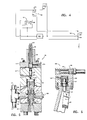
- FIG. 2 there is illustrated, partially in cross-section, a preferred form of a power assisted valve according to the present invention.
- This valve designated generally 24, is formed within a housing formed from three basic portions 30, 32 and 34. These three housing sections are coupled together by four bolts 36 passing through sections 30 and 32 and threaded into section 34. As illustrated, an'o-ring seal is used to seal section 30 to section 32. No seal is provided between sections 32 and 34 since the junction of these two portions is vented to ambient pressure by vent 38.
- Section 30 includes an outlet 40 for coupling to the dump outlet 29 illustrated in Figure 1.
- the entire housing 24 is of generally cylindrical shape and the outlet 40 lies along the axis of the cylinder and is aligned with other bores passing through the other portions of the housing.
- Section 32 has an essentially cylindrical bore 42 passing along its axis.
- a separate valve seat is provided at the bottom of bore 42 by means of a hardened steel insert 44, which is sealed to the bore 42 by an O-rings.
- a bore 46 having a diameter larger than bore 42 is provided in the lower portion of section 34 of the housing 24.
- Another bore 48 is provided in the upper portion of section 34 and is in communication with bore 46 through a small orifice 50 again preferably lying on the axis of the cylindrical body 24.
- a vent 52 is provided through the side of section 34 to vent the lower portion of bore 48 to ambient pressure.
- Piston 54 comprises a large diameter upper section 56, an intermediate diameter section 58 and a small diameter lower portion 60.
- a pair of ports 62 and 64 are provided in section 32 adjacent the small end 60 of piston 54, for connection to lines 16 and 28 of Figure 1.
- Peripheral seals 66 and 68 in the form of O-rings, are provided on portions 56 and 58 of piston 54. Seal 66 forms a closed chamber between large end 56 of piston 54 and the upper end of bore 46. Likewise seal 68 forms a closed chamber between the intermediate sized portion 58 of piston 54 and the lower end of bore 42.
- vent 38 maintains the portions of bores 42 and 46 between seals 66 and 68 at ambient pressure. Communication beween the chamber above- seal 66 and the chamber below seal 68 is provided by an axial bore 70 and a radial orifice 72, both formed in piston 54.
- a control valve 74 is carried within bore 48 in section 34 of housing 24.
- Valve 74 has a tapered surface 76 on a lower end which mates with the upper end of orifice 50. Normal fluid pressures urge valve 74 away from the orifice 50 so that bores 46 and 48 normally remain in communication with each other.
- the control valve 74 is sealed to bore 48 by means of an O-ring seal 80.
- the dump valve 24 is operated by a solenoid 82.
- the solenoid 82 and a valve cover plate 84 are connected to the upper end of section 34 of valve 24 by means of bolts 86.
- Solenoid 82 includes an armature 88 which extends through the plate 84 into the bore 48 to contact an upper end of control valve 74.
- the electrical wires 28, which are also illustrated in Figure 1, supply necessary electrical current to a coil within solenoid 82 in a conventional manner. When current is supplied to solenoid 82, the armature 88 forces valve 74 downward so that the tapered surface 76 seals the upper end of orifice 50.
- FIG. 3 there is provided a cross-sectional illustration of a portion of the nozzle assembly 18 of Figure 1.
- the assembly 18 includes a rectangular block 88 having a conduit 90 passing through an upper end.
- Conduit 90 is simply a straight through passage adapted for receiving the supply line 18 at one end and the nozzle 12 at the other.
- a cavity 92 is provided in a lower end of the block 88 and carries an electrical switch 94.
- the electrical wires 26 shown in Figure 1 extend from the switch 94 for coupling to the solenoid 82.
- the switch 94 is mechanically coupled to the trigger 20 for manual operation. It is apparent that switch 94 may simply be used to selectively connect or disconnect a source of electrical current to the solenoid 82, but in the preferred ! embodiment the circuitry of Figure 4 is employed to drive solenoid 82 in response to operation of switch 94.
- the switch 94 also illustrated in Figure 3, comprises a single pole double throw switch.
- a coil 82 represents the solenoid of Figure 2.
- the circuitry also include relays 96 and 98 and a 12 volt power supply 100, such as a battery.
- Switch 94 has a normally open fixed contact 102, a normally closed fixed contact 104 and a wiper, or moving contact, 106.
- Relay 96 has a normally closed contact set 108 which is controlled by the position of wiper 106 and the fixed contact 104 of switch 94.
- switch 94 provides power from the power supply 100 to relay 96 which maintains contact pair 108 in an open condition as illustrated.
- the other relay 98 is controlled by the series connection of the contact pair 108 and the normally open contact 102 and wiper 106 of switch 94.
- Relay 98 has a contact pair 110 which is normally open, that is open when the relay 98 is not energized.
- Contact pair 110 in turn controls the flow of current through coil 82 to thereby control the actuation of dump valve 24.
- relay 108 is deactivated so that contact pair,108 closes.
- FIG. 1 With reference now to Figures 1 , to 4, the ⁇ operation of the improved power assisted dump valve 24 in this embodiment will be described.
- the drawings of piston 54 and valve 74 in Figure 2 illustrate the valve 24 in its start up condition when pump 10 is supplying fluid through inlet line 16, but the operator has not called for high pressure fluid by depressing trigger 20. In this condition, substantially all fluid entering port 62 is dumped through the dump port 40 and outlet 29 which does provide a low level of back pressure within the bore 42. This pressure is also applied through the orifice 72 and bore 70 to the orifice 50 and thereby to the upper bore 48.. Since the operator has not activated the solenoid 82, valve 74 is free to float within bore 48 and is lifted away from orifice 50 by this pressure.
- orifice 50 has four times the cross sectional area of the orifice 72.
- orifice 50 may have a diameter of 1/16th inch while orifice 72 has a diameter of 132nd inch.
- a hydraulically actuated dump valve according to the present invention is generally designated 112.
- the lower portions of this valve comprising sections 30, 32 and 34, the valve 74, the pistQn 54 and the dump outlet seat 44 are all identical in construction to the Figure 2 embodiment and need be described no further.
- the piston 54 and valve 74 are illustrated in their closed, that is, operating positions.
- a hydraulic actuator section 114 is substituted for the solenoid 82 of Figure 2.
- Section 114 may be bolted to the top of valve section 34 by bolts 86 in the same manner as solenoid 82 and plate 84 were bolted in Figure 2.
- an O-ring seal 116 is provided between the section 114 and section 34.
- a central bore 118 is provided in section 114 directly above and coaxial with bore 48 in section 34.
- An inlet 120 is provided for supplying hydraulic or pnuematic fluid to the bore 118 to drive valve 74 downward against orifice 50 when an operator calls for high pressure fluid to a nozzle.
- An adjusting stem 122 is threaded into an upper end of section 114 and extends into bore 118 for allowing adjustment of a normal fluid pressure within bore 118.
- a vent 124 is also provided for bleeding air from the bore 118 when hydraulic fluid is employed.
- FIG. 6 a cross-sectional illustration of a nozzle assembly 126 useful with the dump valve of Figure 5 is provided.
- the assembly 126 comprises a block 128 having the chamber 90 identical with that provided in the Figure 3 embodiment.
- a bore 130 is provided in a lower end of block 128 and carries a piston 132.
- a portion 134 of piston 132 extends from the lower end of block 128 for engaging the trigger 20.
- a port 136 provides communication with the portion of bore 130 above piston 132.
- a conduit preferably a flexible hose, connects the port 136 with port 120 of Figure 5.
- FIG. 5 Additional features of this second embodiment of the present invention are illustrated in Figure 5. While in the embodiment illustrated in Figures 1 thru 3, the high pressure fluid passes into port 62, through bore 42, and out of port 64 in normal operation, it is not essential that both ports 62 and 64 be provided. Thus, in the Figure 5 embodiment a sealing plug 138 is installed in the outlet port 64 or alternatively the port 64 could be entirely omitted.
- a pipe "T" fitting 138 has one of its three ports connected to the other port 62 of dump valve 112.
- the conduits 16 and 28 of Figure 1 are connected to the remaining two ports of the "T" fitting 138. It can be seen that with this connection of the dump valve 112, it may be positioned remotely from both the nozzle 12 and the pump 10 and only a single conduit 140 need be run from the "T" fitting 138 to the dump valve 112 itself.
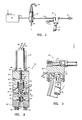
- a mechanically operated but power assisted dump valve according to the present invention is illustrated incorporated into a nozzle assembly generally designated 140.
- This embodiment again uses a dump valve 142 which include sections 32, and 34, valve 74, piston 54 and dump valve seat 44 which are identical to these portions of the dump valves illustrated in both Figures 2 and 5.
- these portions of the dump valve are installed in an inverted position so that valve 74 may be manually actuated by the trigger 20.
- the nozzle 12 is connected directly into port 64 and the inlet line 22 is coupled to the inlet port 62 in section 32 of the dump valve.
- the section 30 illustrated in Figures 2 and 5 is replaced by slightly modified section 144 which provides a side dump port 146 into which a typical dump nozzle 148 is threaded.
- a handle assembly 150 carrying the trigger 20 replaces the solenoid 82 of Figure 2 and the hydraulic actuator section 114 of Figure 5.
- This section 150 may again be bolted on by the same bolts 86 used in the other embodiments.
- Handle 150 carries a sliding piston 152 which transmits force from trigger 20 to the valve 74.
- Additional elements illustrated in Figure 7 include a connecting block 154 and a shoulder stock arrangement 156 which allows an operator to more easily manipulate the high pressure nozzle assembly.
- valve 74 is mechanically driven into engagement with the orifice 50 to in turn cause piston 54 to move into sealing engagement with the valve seat 44 and thereby cause the high pressure fluid to be conducted to nozzle 12.
- the internal functioning of the valve 74 is the same as described above with the other embodiments.
- the dump outlet 148 is actually located at the high pressure nozzle which is a conventional arrangement.
- the operator need apply very little force to the trigger 20 since it takes very little force and a very short stroke to move valve 74 into sealing engagement with orifice 50 and to thereby actuate the piston 54.
- a valve similiar to piston 54 was manually actuated by trigger 20, requiring a much longer stroke and greater force with a result that the operator became fatigued much more quickly.
- the dump valve according to the present invention may be actuated electrically, hydraulically, or mechanically.
- the hydraulic embodiment of Figure 5 would also operate from a pressurized air source with a supply of air controlled from a valve in the nozzle assembly.
- the air source could be switched by a solenoid operated valve located remote from the nozzle assembly and controlled by an electrical switch in the nozzle assembly such as that illustrated in Figure 3.
Abstract
A high pressure fluid system for providing fluid to a hand held nozzle, comprising an improved power assisted dump valve which may be remotely located and controlled. The dump valve includes a stepped piston positioned in a stepped bore with one end of the piston adapted for sealing off a pressure relief outlet. A fluid conduit, preferably a passageway through the piston, conducts high pressure fluid to the valve chamber atthe large diameter end of the piston. A control valve either seals off the large diameter end of the chamber or vents it to ambient pressure so that differential pressure supplied by the working fluid itself drives the valve piston to its open or closed positions. An electrical, hydraulic, or mechanical actuator operates the control valve, remotely if desired, to control the flow of high pressure fluid to the nozzle.
Description
- This invention relates to a high pressure fluid delivery system and in particular to a power assisted dump valve for use in controlling the flow of fluid through a nozzle.
- High pressure fluid delivery systems have been used for many cleaning applications. Many details of such systems are illustrated by U.S. Patent 3,765,607 issued to Pacht on October 16, 1973 and assigned to the assignee of the present invention. Such systems typically use water for cleaning fluid and include a high pressure pump and a hand held nozzle for directing a stream of water at an object to be cleaned. Most such systems also include a valve arrangement, usually in the hand held nozzle assembly, by which the operator can stop and start the flow of high pressure fluid through the nozzle. Due to the fact that the pressures j used in such systems often exceed ten thousand pounds per square inch, the construction of valves which will operate safely is much MOre difficult than it would at first seem. The valves often require considerable force to operate and result in operator fatigue. A power assisted dump valve would therefore be desirable.
- The high pressure flow from the nozzle assembly is usually stopped by simply switching the flow to a large opening to ambient pressure. It is sometimes desirable for the dump outlet to be located remotely from the nozzle while the valve is controlled from the nozzle location. It would therefore be desirable for a dump valve to be adapted for remote actuation.
- Accordingly an object of the present invention is to provide an improved dump valve which requires a relatively short stroke and minimum force to operate.
- Another object of the present invention is to provide a dump valve which may be remotely actuated to control the flow of fluid to a hand held nozzle.
- These and other objects are achieved by providing a power assisted dump valve and means for controlling the operation of the dump valve. The dump valve comprises a piston carried within a housing having a fluid inlet and a dump outlet. The piston is driven by working fluid pressure on opposite ends to selectively close or open the dump outlet. A control valve selectively controls the relationship between forces applied to opposite sides of the piston to control piston position. In a preferred form the dump valve includes a body having a three step bore carrying a three step piston. A large end and intermediate size portion of the piston each fit the stepped bore in fluid tight arrangement. A small end of the piston forms a valve for sealing off or opening a dump outlet. A fluid inlet is in communication with the intermediate sized section of the valve chamber. The large diameter end of the valve chamber is selectively sealed by a control valve. A conduit, preferably formed through the valve piston, supplies high pressure fluid to the large diameter end of the valve chamber so that differential forces acting on the valve piston force it to either open or close the dump outlet. Means are provided at the nozzle assembly for switching the control valve from open to closed positions.
- The present invention may be better understood- from the following detailed description of the preferred embodiments with reference to the accompanying drawings wherein:
- Figure 1 is a partially schematic illustration of an overall high pressure fluid delivery system utilizing a power assisted dump valve of the present invention in a remotely controlled arrangement;
- Figure 2 is a partially cross-sectional illustration of the dump valve of Figure 1;
- Figure 3 is a cross-sectional illustration of a portion of the hand held nozzle assembly of Figure 1;
- Figure 4 is a schematic diagram of a circuit useful with the apparatus of Figures 4 and 5;
- Figure 5 is a cross-sectional illustration of a dump valve employing a hydraulic valve actuator;
- Figure 6 is a cross-sectional illustration of a nozzle assembly including hydraulic pump for use with the Figure 5 valve; and
- Figure 7 is a partially cross-sectional illustration of a nozzle assembly having a mechanically actuated dump valve according to the present invention.
- With reference to Figure 1, there is illustrated a typical high pressure fluid system using a power assisted dump valve according to the present invention. As stated above, such fluid cleaning systems comprise primarily a
high pressure pump 10 and some form ofnozzle 12 for directing pressurized fluid at a surface to be cleaned. Thepump 10 receives low pressure fluid at aninlet 14 and supplies high pressure fluid at anoutlet 16. Thenozzle 12 is typically attached to a hand heldnozzle assembly 18 including some type oftrigger 20 for controlling the flow of fluid fromnozzle 12. Theassembly 18 is typically connected to the pump by means of aflexible hose 22. In the present invention, a remotely actuateddump valve 24 is connected to theoutlet 16 ofpump 10 to control the flow of high pressure fluid entering theline 22. Valve 24 may conveniently be mounted directly tooutlet 16 ofpump 10 or at some convenient positionintermediate pump 10 andnozzle 18, for example near a drain. In any case,valve 24 is, in this embodiment, remote fromnozzle assembly 18. In this embodiment, thevalve 24 is electrically controlled by means of a switch innozzle assembly 18, shown in more detail in Figure 3. Circuitry, such as that shown in Figure 4, interconnects the switch innozzle assembly 18 to thevalve 24, which is solenoid actuated.Electrical wires flexible hose 22, connect thenozzle assembly 18 tovalve 24. The operator of the system of Figure 1 uses this system in exactly the same manner as prior art systems but he must apply only a small amount of force to trigger 20 to actuatevalve 24. In this embodiment the operator does not experience the same level kick upon stopping the high pressure flow or the dumping of fluid at this feet. That is, when the operator releases trigger 20, thevalve 24 dumps the fluids frompump 10 to ambient pressure through adump outlet 29. - With reference now to Figure 2 there is illustrated, partially in cross-section, a preferred form of a power assisted valve according to the present invention. This valve, designated generally 24, is formed within a housing formed from three
basic portions bolts 36 passing throughsections section 34. As illustrated, an'o-ring seal is used to sealsection 30 tosection 32. No seal is provided betweensections vent 38. -
Section 30 includes an outlet 40 for coupling to thedump outlet 29 illustrated in Figure 1. In the preferred embodiment theentire housing 24 is of generally cylindrical shape and the outlet 40 lies along the axis of the cylinder and is aligned with other bores passing through the other portions of the housing.Section 32 has an essentiallycylindrical bore 42 passing along its axis. A separate valve seat is provided at the bottom ofbore 42 by means of a hardenedsteel insert 44, which is sealed to thebore 42 by an O-rings. Abore 46 having a diameter larger thanbore 42 is provided in the lower portion ofsection 34 of thehousing 24. Anotherbore 48 is provided in the upper portion ofsection 34 and is in communication withbore 46 through asmall orifice 50 again preferably lying on the axis of thecylindrical body 24. Avent 52 is provided through the side ofsection 34 to vent the lower portion ofbore 48 to ambient pressure. - The
bores sections housing 24, together form a chamber in which is carried apiston 54. Piston 54 comprises a large diameterupper section 56, anintermediate diameter section 58 and a small diameterlower portion 60. A pair ofports section 32 adjacent thesmall end 60 ofpiston 54, for connection tolines Peripheral seals portions piston 54.Seal 66 forms a closed chamber betweenlarge end 56 ofpiston 54 and the upper end ofbore 46. Likewiseseal 68 forms a closed chamber between the intermediate sizedportion 58 ofpiston 54 and the lower end ofbore 42. Thevent 38 maintains the portions ofbores seals seal 66 and the chamber belowseal 68 is provided by anaxial bore 70 and a radial orifice 72, both formed inpiston 54. - A
control valve 74 is carried withinbore 48 insection 34 ofhousing 24.Valve 74 has a taperedsurface 76 on a lower end which mates with the upper end oforifice 50. Normal fluid pressures urgevalve 74 away from theorifice 50 so that bores 46 and 48 normally remain in communication with each other. Thecontrol valve 74 is sealed to bore 48 by means of an O-ring seal 80. - As noted above, in this embodiment the
dump valve 24 is operated by asolenoid 82. Thesolenoid 82 and avalve cover plate 84 are connected to the upper end ofsection 34 ofvalve 24 by means ofbolts 86.Solenoid 82 includes anarmature 88 which extends through theplate 84 into thebore 48 to contact an upper end ofcontrol valve 74. Theelectrical wires 28, which are also illustrated in Figure 1, supply necessary electrical current to a coil withinsolenoid 82 in a conventional manner. When current is supplied tosolenoid 82, thearmature 88forces valve 74 downward so that the taperedsurface 76 seals the upper end oforifice 50. - With reference now to Figure 3, there is provided a cross-sectional illustration of a portion of the
nozzle assembly 18 of Figure 1. Theassembly 18 includes arectangular block 88 having aconduit 90 passing through an upper end.Conduit 90 is simply a straight through passage adapted for receiving thesupply line 18 at one end and thenozzle 12 at the other. Acavity 92 is provided in a lower end of theblock 88 and carries anelectrical switch 94. Theelectrical wires 26 shown in Figure 1 extend from theswitch 94 for coupling to thesolenoid 82. As illustrated, theswitch 94 is mechanically coupled to thetrigger 20 for manual operation. It is apparent thatswitch 94 may simply be used to selectively connect or disconnect a source of electrical current to thesolenoid 82, but in the preferred ! embodiment the circuitry of Figure 4 is employed to drivesolenoid 82 in response to operation ofswitch 94. - With reference now to Figure 4, circuitry designed for fail-safe operation of the high pressure fluid delivery system of Figure 1 is illustrated. The
switch 94, also illustrated in Figure 3, comprises a single pole double throw switch. Acoil 82 represents the solenoid of Figure 2. The circuitry also includerelays volt power supply 100, such as a battery.Switch 94 has a normally open fixedcontact 102, a normally closed fixedcontact 104 and a wiper, or moving contact, 106.Relay 96 has a normally closed contact set 108 which is controlled by the position ofwiper 106 and the fixedcontact 104 ofswitch 94. Thus, when thetrigger 20 is not depressed, switch 94 provides power from thepower supply 100 to relay 96 which maintainscontact pair 108 in an open condition as illustrated. Theother relay 98 is controlled by the series connection of thecontact pair 108 and the normallyopen contact 102 andwiper 106 ofswitch 94.Relay 98 has acontact pair 110 which is normally open, that is open when therelay 98 is not energized.Contact pair 110 in turn controls the flow of current throughcoil 82 to thereby control the actuation ofdump valve 24. Whentrigger 20 is depressed and thewiper 106 moves away from thecontact 104,relay 108 is deactivated so that contact pair,108 closes. Upon further motion ofwiper 106 in response to movement oftrigger 20 it makes contact with the fixedcontact 102 to complete a circuit which activatesrelay 98. Activation ofrelay 98 closes thecontact pair 110 which then supplies current tocoil 82 to activatedump valve 24 and provide high pressure fluid to thenozzle 12. Upon release ofswitch 20 the high pressure fluid flow should stop whenwiper 106 moves away fromcontact 102 or, in any case, whencontact 106 makes contact with the fixedcontact 104. It is apparent that numerous other circuits would be suitable for controllingsolenoid 82 in response to the activation ofswitch 94. - With reference now to Figures 1 , to 4, the ` operation of the improved power assisted
dump valve 24 in this embodiment will be described. The drawings ofpiston 54 andvalve 74 in Figure 2 illustrate thevalve 24 in its start up condition whenpump 10 is supplying fluid throughinlet line 16, but the operator has not called for high pressure fluid by depressingtrigger 20. In this condition, substantially allfluid entering port 62 is dumped through the dump port 40 andoutlet 29 which does provide a low level of back pressure within thebore 42. This pressure is also applied through the orifice 72 and bore 70 to theorifice 50 and thereby to theupper bore 48.. Since the operator has not activated thesolenoid 82,valve 74 is free to float withinbore 48 and is lifted away fromorifice 50 by this pressure. As a result, the chamber abovepiston 54 is vented to atmospheric pressure through theport 52. In this preferred embodiment,orifice 50 has four times the cross sectional area of the orifice 72. For example,orifice 50 may have a diameter of 1/16th inch while orifice 72 has a diameter of 132nd inch. As a result, a majority of the pressure drop occurs at orifice 72 andpiston 54 experiences a differential force lifting it to its upward position in which the dump outlet 40 is open so that essentially no high pressure fluid is supplied to port 64 which is coupled to thenozzle 12. - When the operator calls for high pressure fluid at
nozzle 12 by depressingtrigger 20, current is applied tosolenoid 82 which drives itsarmature 88 downward forcingvalve 74 to seal offorifice 50. As a result, fluid flowing through the orifice 72 into the chamber abovepiston 54 is no longer vented to ambient pressure. Pressures below and abovepiston 54 are therefore equalized. However, since theupper end 56·ofpiston 54 has a larger diameter than thelower end 60, a differential force is applied topiston 54 driving it downwards to a position where itcontacts seat 44. These positions ofvalve 74 andpiston 54 are illustrated in Figure 5. The rate of downward motion ofpiston 54 is related to the size of orifice 72. As thelower end 60 ofpiston 54 approachesseat 44 the dump outlet 40 is sealed off and fluid supplied toinlet 62 must flow outport 64 to thenozzle 12. As a result, the pressure withinbore 42 rises to its operating level and drives thepiston 54 with greater force towards theseat 44. When thepiston 54 actuallycontacts seat 44, the area ofpiston 54 experiencing an upward force is decreased since the port 40 exposes thesmall diameter end 60 to ambient pressure. As a result, the differentialpressure holding piston 54 againstseat 44 is further increased. It can be seen that considerable force is applied topiston 54 holding it firmly against the dumpoutlet valve seat 44 under operating conditions. - During normal operating conditions, it can be seen that the maximum operating pressure is applied to the tapered
surface 76 ofvalve 74. But since theorifice 50 is of very small diameter, the force required to holdvalve 74 down is relatively small. In this electrically operated embodiment thesolenoid 82 supplies the required force so that the operator need only depresstrigger 20 with sufficient force to close theswitch 94. When the operator no longer desires the flow of high pressure fluid tonozzle 12, he simply releases thetrigger 20 and the above process is reversed. When current is no longer applied to solenoid 82 thearmature 88 is withdrawn into the solenoid and the pressure inorifice 50lifts valve 74 away from its seated position. The chamber abovepiston 54 is thereby vented to ambient pressure and the high level of operating pressure belowpiston 54 quickly lifts the piston away fromseat 44 so that fluid enteringport 62 is vented through the dump outlet 40. - With reference now to Figure 5 a hydraulically actuated dump valve according to the present invention is generally designated 112. The lower portions of this
valve comprising sections valve 74, thepistQn 54 and thedump outlet seat 44 are all identical in construction to the Figure 2 embodiment and need be described no further. In this Figure 5 illustration, thepiston 54 andvalve 74 are illustrated in their closed, that is, operating positions. In this embodiment, ahydraulic actuator section 114 is substituted for thesolenoid 82 of Figure 2.Section 114 may be bolted to the top ofvalve section 34 bybolts 86 in the same manner assolenoid 82 andplate 84 were bolted in Figure 2. In addition, an O-ring seal 116 is provided between thesection 114 andsection 34. Acentral bore 118 is provided insection 114 directly above and coaxial withbore 48 insection 34. Aninlet 120 is provided for supplying hydraulic or pnuematic fluid to thebore 118 to drivevalve 74 downward againstorifice 50 when an operator calls for high pressure fluid to a nozzle. An adjustingstem 122 is threaded into an upper end ofsection 114 and extends intobore 118 for allowing adjustment of a normal fluid pressure withinbore 118. Avent 124 is also provided for bleeding air from thebore 118 when hydraulic fluid is employed. - With reference to Figure 6, a cross-sectional illustration of a
nozzle assembly 126 useful with the dump valve of Figure 5 is provided. Theassembly 126 comprises ablock 128 having thechamber 90 identical with that provided in the Figure 3 embodiment. Abore 130 is provided in a lower end ofblock 128 and carries apiston 132. Aportion 134 ofpiston 132 extends from the lower end ofblock 128 for engaging thetrigger 20. Aport 136 provides communication with the portion ofbore 130 abovepiston 132. In normal operation a conduit, preferably a flexible hose, connects theport 136 withport 120 of Figure 5. As a result, it can be seen that when bore 130 of Figure 6, bore 18 of Figure 5 and an interconnecting conduct are all filled with hydraulic fluid, the depression oftrigger 20hydraulically drives valve 74 downward to seal offorifice 50 and actuatedump valve 24 as described above. t - Additional features of this second embodiment of the present invention are illustrated in Figure 5. While in the embodiment illustrated in Figures 1 thru 3, the high pressure fluid passes into
port 62, throughbore 42, and out ofport 64 in normal operation, it is not essential that bothports plug 138 is installed in theoutlet port 64 or alternatively theport 64 could be entirely omitted. A pipe "T" fitting 138 has one of its three ports connected to theother port 62 ofdump valve 112. Theconduits dump valve 112, it may be positioned remotely from both thenozzle 12 and thepump 10 and only asingle conduit 140 need be run from the "T" fitting 138 to thedump valve 112 itself. - The operation of the embodiment illustrated in Figures 5 and 6 is externally identical to that of the first embodiment. The operator calls for high pressure fluid to
nozzle 12 by depressingtrigger 20.Trigger 20 drivespiston 132 intobore 130 which in turn drives hydraulic fluid intobore 118 in thedump valve 112 and forces thevalve 74 downward into sealing engagement withorifice 50 as illustrated in Figure 5. As described above, whenorifice 50 is sealed byvalve 74, differential forces acting onpiston 54 force it downward into sealing engagement with theseat 44 to thereby seal off the dump outlet and force the fluids frompump 10 to be conducted tonozzle 12. Upon release oftrigger 20 by the operator, hydraulic pressure withindump valve 112 lifts thevalve 74 and forces the hydraulic fluid back intobore 130 in thenozzle assembly 126. If desired, thepiston 132 in thenozzle assembly 126 may be assisted by a coil spring as illustrated. - With reference now to Figure 7, a mechanically operated but power assisted dump valve according to the present invention is illustrated incorporated into a nozzle assembly generally designated 140.. This embodiment again uses a
dump valve 142 which includesections valve 74,piston 54 and dumpvalve seat 44 which are identical to these portions of the dump valves illustrated in both Figures 2 and 5. In this embodiment these portions of the dump valve are installed in an inverted position so thatvalve 74 may be manually actuated by thetrigger 20. Thenozzle 12 is connected directly intoport 64 and theinlet line 22 is coupled to theinlet port 62 insection 32 of the dump valve. Thesection 30 illustrated in Figures 2 and 5 is replaced by slightly modifiedsection 144 which provides aside dump port 146 into which atypical dump nozzle 148 is threaded. Ahandle assembly 150 carrying thetrigger 20 replaces thesolenoid 82 of Figure 2 and thehydraulic actuator section 114 of Figure 5. Thissection 150 may again be bolted on by thesame bolts 86 used in the other embodiments. Handle 150 carries a slidingpiston 152 which transmits force fromtrigger 20 to thevalve 74. Additional elements illustrated in Figure 7 include a connectingblock 154 and ashoulder stock arrangement 156 which allows an operator to more easily manipulate the high pressure nozzle assembly. - The operation of this Figure 7 embodiment is again basically conventional in so far as the operator is concerned. Upon depressing the
trigger 20,valve 74 is mechanically driven into engagement with theorifice 50 to inturn cause piston 54 to move into sealing engagement with thevalve seat 44 and thereby cause the high pressure fluid to be conducted tonozzle 12. The internal functioning of thevalve 74 is the same as described above with the other embodiments. The primary difference in this embodiment is that thedump outlet 148 is actually located at the high pressure nozzle which is a conventional arrangement. In this Figure 7 embodiment however, the operator need apply very little force to thetrigger 20 since it takes very little force and a very short stroke to movevalve 74 into sealing engagement withorifice 50 and to thereby actuate thepiston 54. In previously known apparatus, a valve similiar topiston 54 was manually actuated bytrigger 20, requiring a much longer stroke and greater force with a result that the operator became fatigued much more quickly. - As illustrated by these various embodiments, the dump valve according to the present invention may be actuated electrically, hydraulically, or mechanically. The hydraulic embodiment of Figure 5 would also operate from a pressurized air source with a supply of air controlled from a valve in the nozzle assembly. Likewise the air source could be switched by a solenoid operated valve located remote from the nozzle assembly and controlled by an electrical switch in the nozzle assembly such as that illustrated in Figure 3.
- While the present invention has been illustrated and described in terms of specific apparatus and methods of use, it is apparent that various other modifications may be made within the scope of the present invention as defined by the appended claims.
Claims (18)
1. A valve for controlling the flow of fluid from a high pressure pump to a nozzle comprising:
a housing having a fluid inlet and a dump outlet;
a dump valve means in said housing for selectively communicating said inlet with said dump outlet, said dump valve means being exposed on opposite sides to the pressure of fluid received in said fluid inlet,
control valve means for causing actuation of said dump valve means by changing the relationship between the pressure acting on opposite sides of said dump valve means; and
means for actuating said control valve means.
2. A valve according to claim 1 wherein said fluid inlet-is connected to a conduit conducting fluid from said high pressure pump to said nozzle and said means for actuating is at least partially located with and physically attached to said nozzle;
said means for actuating comprising a solenoid having an armature coupled to said control valve means, a source of electrical current, a manually operable switch, and means for supplying electrical current to said solenoid in response to operation of said switch.
3. A valve according to claim 1 wherein said fluid inlet is connected to a conduit conducting fluid from said high pressure pump to said nozzle and said means for actuating is at least partially located with and physically attached to said nozzle;
said means for actuating comprising hydraulic cylinder means coupled to said control valve means, and a manually operable hydraulic pump coupled to said hydraulic cylinder means.
4. A valve according to claim 1 wherein said fluid inlet is connected to a conduit conducting fluid from said high pressure pump to said nozzle and said means for actuating is at least partially located with and physically attached to said nozzle;
said means for actuating comprising a manually operable trigger, said trigger mechanically coupled to said control valve means.
5. Apparatus for controlling the flow of fluid from a high pressure pump to a nozzle comprising:
a housing having a stepped bore, said bore having large and small diameter portions;
a stepped piston having corresponding large and small diameter ends carried in said stepped bore;
said housing having a fluid inlet and a dump outlet in said small diameter portion, said dump outlet positioned to be selectively closed by a surface of said piston small end;
conduit means for conducting fluid from said bore small end to said bore large end;
control valve means for selectively venting said bore large end to ambient pressure; and
actuation means comprising a solenoid having an armature coupled to said control valve means, a source of electrical current, a manually operable switch carried by a nozzle, and means for supplying electrical current to said solenoid in response to operation of said switch.
6. Apparatus for controlling the flow of fluid from a high pressure pump to a nozzle comprising:
a housing having a stepped bore, said bore having large and small diameter portions;
a stepped piston having corresponding large and small diameter ends carried in said stepped bore;
said housing having a fluid inlet and a dump outlet in said small diameter portion, said dump outlet positioned to be selectively closed by a surface of said piston small end;
conduit means for conducting fluid from said bore small end to said bore large end;
control valve means including a vent providing communication between said bore large end and ambient pressure and a control valve slideably carried in a bore having a first end for closing said vent and a second end defining a wall of a fluid tight chamber; and
actuation means comprising a manually operable hydraulic fluid pump carried by a nozzle, said pump having an outlet coupled to said fluid tight chamber, whereby upon manual operation of said pump said control valve is driven into engagement with said vent.
7. Apparatus for controlling the flow of fluid from a high pressure pump to a nozzle comprising:
a housing having a stepped bore, said bore having large and small diameter portions;
a stepped piston having corresponding large and small diameter ends carried in said stepped bore;
said housing having a fluid inlet and a dump outlet in said small diameter portion, said dump outlet positioned to be selectively closed by a surface of said piston small end;
conduit means for conducting fluid from said bore small end to said bore large end;
control valve means for selectively venting said bore large end to ambient pressure; and
actuation means comprising a manually operable trigger carried by a nozzle and mechanically coupled to said control valve means.
8. A fluid system for supplying a high pressure stream of fluid, comprising a pump having a low pressure fluid inlet and a high pressure outlet, a valve coupled to said high pressure fluid outlet to control fluid flow, and a nozzle assembly coupled to said valve and a dump valve which comprises:
a housing having a stepped cylindrical valve chamber having first, second, and third sections, said second section positioned between said first and third sections and having a diameter smaller than said first section and larger than said third section,
a piston slideably carried within said chamber having first and second portions having diameters corresponding to and carried within said first and second chamber sections respectively, and a third portion, opposite said first portion, having a diameter smaller than said second portion for sealingly engaging said chamber third section,
at least one high pressure fluid port in communication with said chamber second section, and a pressure relief port in communication with said chamber third section,
first and second peripheral seals carried on said piston first and second portions respectively, said second seal positioned above said at least one high pressure fluid port,
control valve means for selectively closing and venting to ambient pressure said chamber first section above said piston first peripheral seal, and
conduit means for conducting fluid from said valve chamber second section below said piston second seal to said valve chamber first section above said piston first seal.
9. A system according to claim 8 which includes means for venting said chamber first and second sections between said piston first and second seals to ambient pressure.
10. A system according to either of claims 8 and 9 wherein said conduit means comprises a passageway formed in said piston.
11. A system according to claim 10 wherein said conduit means includes a small diameter orifice for providing a pressure drop across said piston when said control valve means vents said chamber first I section above said peripheral seal to ambient pressure.
12. A system according to any one of claims 8 to 11 wherein said chamber third section comprises an insert carried within an extension of said chamber second section.
13. A system according to any one of claims 8 to 12 wherein said control valve means includes a control valve bore, a passageway extending from said valve chamber first section to a first end of said control valve bore and terminating in a control valve seat at said bore, a vent to ambient pressure coupled to said bore first end, a control valve slideably carried within said bore having a tapered surface on a first end for sealingly engaging said control valve seat, and actuator means for forcing said control valve to said bore first end and into engagement with said control valve seat.
14. A system according to claim 13 wherein said actuator means comprises a manually operable fluid pump attached to said nozzle assembly having an outlet coupled to a second end of said control valve bore, whereby upon manual operation of said pump fluid pressure drives said control valve to said bore first end.
15. A system according to claim 13 wherein said actuator means comprises a solenoid adjacent to said control valve bore first end, said solenoid having an armature positioned to force said control valve to said bore first end in response to application of electrical current to said solenoid, a source of electrical current, and switch means at least partly carried within said nozzle assembly and coupled to said source of electrical current and said solenoid for selectively applying electrical current to said solenoid.
16. A system according to claim 15 wherein said switch means includes an electrical switch carried within said nozzle assembly and relay means connected to said switch, to said solenoid, and to said source of electrical power for selectively applying electrical current to said solenoid in response to operation of said switch.
17. A system according to any one of claims 8 to 16 whe ein said conduit means is of substantially smaller diameter than said passageway whereby a pressure drop is provided across said piston when said control valve vents said chamber first section to ambient pressure.
18. A system according to any one of claims 8 to 17 wherein said dump valve is formed integrally with said nozzle assembly, said nozzle assembly includes a trigger for controlling fluid flow to a nozzle and the control valve is mechanically coupled to said trigger.
Applications Claiming Priority (2)
| Application Number | Priority Date | Filing Date | Title |
|---|---|---|---|
| US90401 | 1979-11-01 | ||
| US06/090,401 US4349154A (en) | 1979-11-01 | 1979-11-01 | Power assisted dump valve |
Publications (2)
| Publication Number | Publication Date |
|---|---|
| EP0028501A2 true EP0028501A2 (en) | 1981-05-13 |
| EP0028501A3 EP0028501A3 (en) | 1981-12-02 |
Family
ID=22222620
Family Applications (1)
| Application Number | Title | Priority Date | Filing Date |
|---|---|---|---|
| EP80303846A Withdrawn EP0028501A3 (en) | 1979-11-01 | 1980-10-29 | Power assisted dump valve |
Country Status (3)
| Country | Link |
|---|---|
| US (1) | US4349154A (en) |
| EP (1) | EP0028501A3 (en) |
| CA (1) | CA1148586A (en) |
Cited By (2)
| Publication number | Priority date | Publication date | Assignee | Title |
|---|---|---|---|---|
| FR2611538A1 (en) * | 1987-02-27 | 1988-09-09 | Graco France Sa | Installation for supplying a semi-liquid or liquid fluid which may or may not be compressible |
| US4848721A (en) * | 1989-01-03 | 1989-07-18 | Stanislav Chudakov | Hydraulic valve with integrated solenoid |
Families Citing this family (20)
| Publication number | Priority date | Publication date | Assignee | Title |
|---|---|---|---|---|
| US4602740A (en) * | 1982-10-12 | 1986-07-29 | Stachowiak J Edward | Fluid control system |
| DE3313249A1 (en) * | 1983-04-13 | 1984-10-25 | Woma-Apparatebau Wolfgang Maasberg & Co Gmbh, 4100 Duisburg | HIGH PRESSURE WATER JET SYSTEM |
| US4593858A (en) * | 1985-04-01 | 1986-06-10 | Butterworth, Inc. | Fail-safe high pressure fluid delivery system |
| JPH036848A (en) * | 1989-06-03 | 1991-01-14 | Hitachi Ltd | Semiconductor cooling module |
| US5297777A (en) * | 1990-12-20 | 1994-03-29 | Jetec Company | Instant on-off valve for high-pressure fluids |
| US5524821A (en) * | 1990-12-20 | 1996-06-11 | Jetec Company | Method and apparatus for using a high-pressure fluid jet |
| US5799688A (en) * | 1990-12-20 | 1998-09-01 | Jetec Company | Automatic flow control valve |
| US5259557A (en) * | 1991-09-25 | 1993-11-09 | Ecolab Inc. | Solution proportioner and dispensing system |
| US5253808A (en) * | 1992-06-16 | 1993-10-19 | Butterworth Jetting Systems, Inc. | Power assisted dump valve |
| US5312040A (en) * | 1992-11-13 | 1994-05-17 | Aqua-Dyne, Inc. | Non-clogging slurry nozzle apparatus and method |
| US5398715A (en) * | 1993-04-15 | 1995-03-21 | Butterworth Jetting Systems Inc. | Constant pressure valve and method |
| JPH08511468A (en) * | 1993-06-10 | 1996-12-03 | エコラブ インコーポレイテッド | Concentrate dilution system |
| US5727186A (en) * | 1994-02-01 | 1998-03-10 | The Boc Group Plc | Simulation apparatus and gas dispensing device used in conjunction therewith |
| US5503334A (en) * | 1994-05-27 | 1996-04-02 | Butterworth Jetting Systems, Inc. | Swivel jet assembly |
| US5636789A (en) * | 1995-05-01 | 1997-06-10 | Nlb Corp | Fluid delivery system |
| US5938120A (en) * | 1997-06-13 | 1999-08-17 | Abbott Laboratories | Fluid system and method |
| US6000637A (en) * | 1998-01-20 | 1999-12-14 | Duncan; Gordon | High pressure water gun |
| DE10306927A1 (en) * | 2003-02-19 | 2004-09-09 | Hammelmann Maschinenfabrik Gmbh | Pressure relief valve |
| US9364868B2 (en) * | 2013-09-05 | 2016-06-14 | Federal Signal Corporation | Adjustable stock assembly for fluid spray gun and methods |
| US10533276B2 (en) * | 2017-08-07 | 2020-01-14 | Haier Us Appliance Solutions, Inc. | Extendable nozzle assembly for a washing machine appliance |
Citations (4)
| Publication number | Priority date | Publication date | Assignee | Title |
|---|---|---|---|---|
| US2622618A (en) * | 1949-01-21 | 1952-12-23 | United Aircraft Prod | Electromagnetically controlled valve |
| US3765607A (en) * | 1972-08-04 | 1973-10-16 | Partek Corp | High pressure fluid system and nozzle and valve assembly therefore |
| US3986523A (en) * | 1974-10-09 | 1976-10-19 | Partek Corporation Of Houston | High pressure fluid system |
| US4061271A (en) * | 1976-10-13 | 1977-12-06 | Kimbrough Wade L | Control system for high pressure hydraulic system |
Family Cites Families (7)
| Publication number | Priority date | Publication date | Assignee | Title |
|---|---|---|---|---|
| US2913005A (en) * | 1956-07-23 | 1959-11-17 | Hughes Tool Co | Pilot-actuated control valve |
| US3140049A (en) * | 1962-11-28 | 1964-07-07 | Britt Tech Corp | Cleaning apparatus with relief control valve |
| US3454030A (en) * | 1966-02-28 | 1969-07-08 | Bicor Products Inc | Pressurized washing system |
| US3628727A (en) * | 1969-12-22 | 1971-12-21 | Harlan T Gjerde | High-pressure spray device |
| US3604459A (en) * | 1970-02-24 | 1971-09-14 | Nils O Rosaen | Cartridge valve |
| JPS5421912B2 (en) * | 1971-12-02 | 1979-08-02 | ||
| US3885739A (en) * | 1974-01-02 | 1975-05-27 | Phillip E Tuttle | Pressure fluid cleaning device |
-
1979
- 1979-11-01 US US06/090,401 patent/US4349154A/en not_active Expired - Lifetime
-
1980
- 1980-10-27 CA CA000363295A patent/CA1148586A/en not_active Expired
- 1980-10-29 EP EP80303846A patent/EP0028501A3/en not_active Withdrawn
Patent Citations (4)
| Publication number | Priority date | Publication date | Assignee | Title |
|---|---|---|---|---|
| US2622618A (en) * | 1949-01-21 | 1952-12-23 | United Aircraft Prod | Electromagnetically controlled valve |
| US3765607A (en) * | 1972-08-04 | 1973-10-16 | Partek Corp | High pressure fluid system and nozzle and valve assembly therefore |
| US3986523A (en) * | 1974-10-09 | 1976-10-19 | Partek Corporation Of Houston | High pressure fluid system |
| US4061271A (en) * | 1976-10-13 | 1977-12-06 | Kimbrough Wade L | Control system for high pressure hydraulic system |
Cited By (2)
| Publication number | Priority date | Publication date | Assignee | Title |
|---|---|---|---|---|
| FR2611538A1 (en) * | 1987-02-27 | 1988-09-09 | Graco France Sa | Installation for supplying a semi-liquid or liquid fluid which may or may not be compressible |
| US4848721A (en) * | 1989-01-03 | 1989-07-18 | Stanislav Chudakov | Hydraulic valve with integrated solenoid |
Also Published As
| Publication number | Publication date |
|---|---|
| CA1148586A (en) | 1983-06-21 |
| EP0028501A3 (en) | 1981-12-02 |
| US4349154A (en) | 1982-09-14 |
Similar Documents
| Publication | Publication Date | Title |
|---|---|---|
| US4349154A (en) | Power assisted dump valve | |
| US4167247A (en) | Spray control apparatus | |
| US8915480B2 (en) | Valve actuator system | |
| US5358038A (en) | Float operated pneumatic pump | |
| CA2679722C (en) | Valve, actuator and control system therefor | |
| KR100576930B1 (en) | Hydraulic system with three electrohydraulic valves for controlling fluid flow to a load | |
| US4856969A (en) | Fluid powered diaphragm pump with cycle timer | |
| US3372899A (en) | Radio actuated and manually operable pilot valve controls | |
| KR100194508B1 (en) | Valve drive | |
| WO1996041956A1 (en) | Magnetically controlled liquid transfer system | |
| KR950704580A (en) | Vacuum toilet system and its discharge valve | |
| JPH086830B2 (en) | Pilot operated coolant control valve | |
| WO2002018800A3 (en) | Pilot solenoid control valve with an emergency operator | |
| US4748896A (en) | Safety valve assembly | |
| US4460152A (en) | Hand pump with automatic lock-out | |
| US6279594B1 (en) | Flow actuated valve | |
| US20190264714A1 (en) | Electro-hydraulic valve actuator having modular manifold with configurable redundancy | |
| EP0273677A2 (en) | Flow controller and a high-pressure liquid system | |
| JPH10220409A (en) | Directional control valve device | |
| MXPA01003109A (en) | Air powered hydraulic jack with load sensing auto shut-off air control. | |
| US3584647A (en) | Solenoid pilot dump combination directional control valve | |
| US6740827B1 (en) | Bi-directional piloted solenoid-operated valve | |
| JPH0238768A (en) | Fluid control valve | |
| KR100286131B1 (en) | Clutch control system | |
| US3845508A (en) | Water closet control system |
Legal Events
| Date | Code | Title | Description |
|---|---|---|---|
| PUAI | Public reference made under article 153(3) epc to a published international application that has entered the european phase |
Free format text: ORIGINAL CODE: 0009012 |
|
| AK | Designated contracting states |
Designated state(s): BE CH DE FR GB NL SE |
|
| PUAL | Search report despatched |
Free format text: ORIGINAL CODE: 0009013 |
|
| AK | Designated contracting states |
Designated state(s): BE CH DE FR GB NL SE |
|
| 17P | Request for examination filed |
Effective date: 19811022 |
|
| STAA | Information on the status of an ep patent application or granted ep patent |
Free format text: STATUS: THE APPLICATION IS DEEMED TO BE WITHDRAWN |
|
| 18D | Application deemed to be withdrawn |
Effective date: 19880502 |
|
| RIN1 | Information on inventor provided before grant (corrected) |
Inventor name: PACHT, AMOS |