EP0028142B1 - Fault detecting sensor and method of detecting faults therewith - Google Patents
Fault detecting sensor and method of detecting faults therewith Download PDFInfo
- Publication number
- EP0028142B1 EP0028142B1 EP80303775A EP80303775A EP0028142B1 EP 0028142 B1 EP0028142 B1 EP 0028142B1 EP 80303775 A EP80303775 A EP 80303775A EP 80303775 A EP80303775 A EP 80303775A EP 0028142 B1 EP0028142 B1 EP 0028142B1
- Authority
- EP
- European Patent Office
- Prior art keywords
- sensor
- fault condition
- sensor according
- resistivity
- fault
- Prior art date
- Legal status (The legal status is an assumption and is not a legal conclusion. Google has not performed a legal analysis and makes no representation as to the accuracy of the status listed.)
- Expired
Links
- 238000000034 method Methods 0.000 title claims description 6
- 239000010410 layer Substances 0.000 claims description 18
- 239000000203 mixture Substances 0.000 claims description 17
- 239000004020 conductor Substances 0.000 claims description 16
- 229920001940 conductive polymer Polymers 0.000 claims description 12
- 239000000463 material Substances 0.000 claims description 8
- 239000003990 capacitor Substances 0.000 claims description 7
- 229920000642 polymer Polymers 0.000 claims description 7
- 239000007787 solid Substances 0.000 claims description 5
- 239000012530 fluid Substances 0.000 claims description 4
- 239000011241 protective layer Substances 0.000 claims description 4
- 239000002245 particle Substances 0.000 claims description 3
- 239000003989 dielectric material Substances 0.000 claims description 2
- 238000012544 monitoring process Methods 0.000 claims description 2
- 239000007788 liquid Substances 0.000 description 4
- YXFVVABEGXRONW-UHFFFAOYSA-N Toluene Chemical compound CC1=CC=CC=C1 YXFVVABEGXRONW-UHFFFAOYSA-N 0.000 description 3
- 238000010586 diagram Methods 0.000 description 3
- 229920001903 high density polyethylene Polymers 0.000 description 3
- 239000004700 high-density polyethylene Substances 0.000 description 3
- 239000002184 metal Substances 0.000 description 3
- 229910052751 metal Inorganic materials 0.000 description 3
- 239000002966 varnish Substances 0.000 description 3
- 239000004215 Carbon black (E152) Substances 0.000 description 2
- 239000006229 carbon black Substances 0.000 description 2
- 230000009977 dual effect Effects 0.000 description 2
- 229930195733 hydrocarbon Natural products 0.000 description 2
- 150000002430 hydrocarbons Chemical class 0.000 description 2
- 238000005259 measurement Methods 0.000 description 2
- -1 polyethylene Polymers 0.000 description 2
- 229920000098 polyolefin Polymers 0.000 description 2
- XLYOFNOQVPJJNP-UHFFFAOYSA-N water Substances O XLYOFNOQVPJJNP-UHFFFAOYSA-N 0.000 description 2
- XOUQAVYLRNOXDO-UHFFFAOYSA-N 2-tert-butyl-5-methylphenol Chemical compound CC1=CC=C(C(C)(C)C)C(O)=C1 XOUQAVYLRNOXDO-UHFFFAOYSA-N 0.000 description 1
- OKTJSMMVPCPJKN-UHFFFAOYSA-N Carbon Chemical compound [C] OKTJSMMVPCPJKN-UHFFFAOYSA-N 0.000 description 1
- RYGMFSIKBFXOCR-UHFFFAOYSA-N Copper Chemical compound [Cu] RYGMFSIKBFXOCR-UHFFFAOYSA-N 0.000 description 1
- 244000043261 Hevea brasiliensis Species 0.000 description 1
- 229920000339 Marlex Polymers 0.000 description 1
- 239000004698 Polyethylene Substances 0.000 description 1
- 239000004743 Polypropylene Substances 0.000 description 1
- 239000004372 Polyvinyl alcohol Substances 0.000 description 1
- 239000003963 antioxidant agent Substances 0.000 description 1
- 230000003078 antioxidant effect Effects 0.000 description 1
- 238000013329 compounding Methods 0.000 description 1
- 229910052802 copper Inorganic materials 0.000 description 1
- 239000010949 copper Substances 0.000 description 1
- 239000004078 cryogenic material Substances 0.000 description 1
- 230000000694 effects Effects 0.000 description 1
- 238000010894 electron beam technology Methods 0.000 description 1
- 229920002313 fluoropolymer Polymers 0.000 description 1
- 239000004811 fluoropolymer Substances 0.000 description 1
- 239000004615 ingredient Substances 0.000 description 1
- 238000009413 insulation Methods 0.000 description 1
- 239000011159 matrix material Substances 0.000 description 1
- 229920003052 natural elastomer Polymers 0.000 description 1
- 229920001194 natural rubber Polymers 0.000 description 1
- 229920000620 organic polymer Polymers 0.000 description 1
- 230000000737 periodic effect Effects 0.000 description 1
- 239000003208 petroleum Substances 0.000 description 1
- 229920000573 polyethylene Polymers 0.000 description 1
- 229920001155 polypropylene Polymers 0.000 description 1
- 229920002451 polyvinyl alcohol Polymers 0.000 description 1
Images

Classifications
-
- G—PHYSICS
- G01—MEASURING; TESTING
- G01M—TESTING STATIC OR DYNAMIC BALANCE OF MACHINES OR STRUCTURES; TESTING OF STRUCTURES OR APPARATUS, NOT OTHERWISE PROVIDED FOR
- G01M3/00—Investigating fluid-tightness of structures
- G01M3/02—Investigating fluid-tightness of structures by using fluid or vacuum
- G01M3/04—Investigating fluid-tightness of structures by using fluid or vacuum by detecting the presence of fluid at the leakage point
- G01M3/16—Investigating fluid-tightness of structures by using fluid or vacuum by detecting the presence of fluid at the leakage point using electric detection means
- G01M3/165—Investigating fluid-tightness of structures by using fluid or vacuum by detecting the presence of fluid at the leakage point using electric detection means by means of cables or similar elongated devices, e.g. tapes
-
- G—PHYSICS
- G01—MEASURING; TESTING
- G01K—MEASURING TEMPERATURE; MEASURING QUANTITY OF HEAT; THERMALLY-SENSITIVE ELEMENTS NOT OTHERWISE PROVIDED FOR
- G01K3/00—Thermometers giving results other than momentary value of temperature
-
- G—PHYSICS
- G01—MEASURING; TESTING
- G01M—TESTING STATIC OR DYNAMIC BALANCE OF MACHINES OR STRUCTURES; TESTING OF STRUCTURES OR APPARATUS, NOT OTHERWISE PROVIDED FOR
- G01M3/00—Investigating fluid-tightness of structures
- G01M3/002—Investigating fluid-tightness of structures by using thermal means
-
- G—PHYSICS
- G01—MEASURING; TESTING
- G01M—TESTING STATIC OR DYNAMIC BALANCE OF MACHINES OR STRUCTURES; TESTING OF STRUCTURES OR APPARATUS, NOT OTHERWISE PROVIDED FOR
- G01M3/00—Investigating fluid-tightness of structures
- G01M3/02—Investigating fluid-tightness of structures by using fluid or vacuum
- G01M3/04—Investigating fluid-tightness of structures by using fluid or vacuum by detecting the presence of fluid at the leakage point
- G01M3/042—Investigating fluid-tightness of structures by using fluid or vacuum by detecting the presence of fluid at the leakage point by using materials which expand, contract, disintegrate, or decompose in contact with a fluid
- G01M3/045—Investigating fluid-tightness of structures by using fluid or vacuum by detecting the presence of fluid at the leakage point by using materials which expand, contract, disintegrate, or decompose in contact with a fluid with electrical detection means
Definitions
- This invention relates to sensors for detecting a fault condition, e.g. excessive temperature or leakage of fluid, and to methods of using such sensors.
- U.S. Patent document US-A-4,041,771 discloses a sensor for detecting and locating leaks of cryogenic material.
- the sensor comprises an elongate dielectric tube containing a liquid which will freeze at the reduced temperature in the region of such a leak and which has substantially higher resistivity when frozen than when liquid.
- a conductor is placed outside the dielectric tube, thus forming a capacitor whose capacitance is periodically measured. The capacitance changes when a leak occurs, and the location of the fault can be determined from the extent of the change.
- the present invention provides a sensor for detecting a fault condition in a system, the sensor comprising (a) first electrical conductor, (b) a dielectric element, and (c) a second electrical conductor, arranged to form a capacitor, the second electrical conductor comprising a material the resistivity of which changes upon occurrence of the fault condition, thereby producing a measurable change in capacitance characterised in that the material comprises a solid conductive polymer composition (CPC) comprising solid polymer and electrically conductive particles dispersed in said polymer, which composition increases in resistivity when the sensor is exposed to the fault condition.
- CPC solid conductive polymer composition
- the invention provides a method of monitoring a location to detect the occurrence of a fault condition in a system, which method is characterised by providing the location with a fault-detecting sensor as defined above and periodically measuring the capacitance of the sensor.
- the CPC element should have a resistance such that the capacitance of the whole sensor can be measured under normal fault-free operating conditions.
- the resistivity of the CPC and the dimensions of the CPC element should be selected accordingly.
- the resistance of the CPC element in the fault area should increase to an extent such that the capacitance of only part of the sensor can be measured.
- the decrease in capacitance is a measure of the distance of the fault from the end of the sensor.
- the decrease in capacitance is a measure of the area over which the fault condition exists.
- the unfaulted sensor has substantially constant capacitance per unit length or area, and generally the sensor will be of constant cross-section.
- the fault condition which is detected may be any fault which causes at least a part of the CPC element to increase in resistance to a level such that the capacitance of the sensor drops.
- One such fault is an excessive temperature, in which case the CPC should be one which exhibits PTC behavior with a switching temperature (T s ) in the region of the excessive temperature which is to be detected.
- T s switching temperature
- Such excessive temperatures may arise, for example, in localised hot spots in dryers for agricultural products or in high voltage electrical cables.
- Another such fault is exposure of at least part of the CPC element to a fluid (e.g. a liquid, vaporised liquid or gas which has leaked from a tank or pipe or other conduit) which is absorbed by the CPC and which, when absorbed, causes the resistivity of the CPC to rise.
- a change in the pressure on the sensor can also be a fault condition.
- fault condition is used herein in a broad sense to include a condition which is not in itself harmful to the apparatus to be protected, but which is induced by a harmful condition and which effects the desired change in the resistivity of the CPC.
- the novel sensors will often comprise an outer protective layer, usually of dielectric material and usually in physical contact with the CPC element.
- the outer layer should be composed of a material which is permeable to the fluid which is present as a result of the leak, for example polyethylene, polypropylene or natural rubber for hydrocarbon leaks and polyvinyl alcohol for water leaks.
- the protective layer may also contain a metallic braid or other material to improve the mechanical properties of the sensor.
- Conductive polymer compositions are well known. Compositions of low resistivity, e.g. less than 10 ohm.cm, preferably less than 1 ohm.cm, are preferred. Compositions which exhibit PTC behavior are essential when an over-temperature is to be detected and are often preferred even when another fault condition is to be detected. Reference may be made for example to DE-A-2948350 (US-A-4237441
- the conductive particles preferably comprise carbon black.
- the polymer matrix preferably comprises a crystalline polymer, e.g. a polyolefin or a fluoropolymer.
- the CPC is preferably cross-linked.
- the switching temperature (T s ) of the CPC will be selected with a view to the temperature which is regarded as excessive (if excessively high temperature is the expected fault condition) or with a view to ensuring that the resistivity of the CPC does not increase substantially as a result of expected temperature changes (where another type of fault condition is expected).
- the T s may be for example at least 50°C, e.g. 50 to 150°C, or higher, e.g. at least 120°C.
- the CPC should increase in resistivity by a factor of at least 4, preferably at least 8, over a temperature range of 10°C, preferably 5°C.
- the electrical conductor will usually be composed of a metal or another material whose resistivity is less than that of the CPC and is preferably substantially invariable under normal operating conditions and under the fault conditions.
- the dielectric element may for example be composed of an insulating varnish or an extruded layer of an organic polymer.
- the sensor is preferably in the form of a cable, for example one in which the dielectric element surrounds the conductor (typically a metal wire) and is in turn surrounded by the conductive polymer element, or one in which the conductor, dielectric and conductive polymer element are elongated flat layers.
- the dielectric element surrounds the conductor (typically a metal wire) and is in turn surrounded by the conductive polymer element, or one in which the conductor, dielectric and conductive polymer element are elongated flat layers.
- Periodic measurement of the capacitance of the sensor, and comparison of the measured capacitance with the unfaulted capacitance, can readily be carried out using conventional electronically controlled equipment.
- a plurality of line sensors arranged in a two- or three-dimensional grid can be employed in combination to locate a fault in two or three dimensions.
- the CPC element will normally be placed as close as possible to the expected origin of the fault condition.
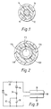
- the senor comprises a round metal wire 10 which is surrounded in turn by concentric layer 12 of an insulating varnish, layer 14 of a CPC and layer 16 of an insulating polymer.
- this shows a sensor which can be used to determine when there has been a loss of pressure in a pressurised system.
- Conductor 114 is of annular cross-section and defines an interior space 112.
- Dielectric layer 116, CPC layer 118 and protective layer 120 surround the conductor 114.
- the components 114, 116, 118 and 120 are such that if the internal pressure in space 112 exceeds the external pressure by a predetermined amount, the tube will expand so that the resistance of the CPC layer increases sharply.
- the sensor is placed in the pressurised system and the pressure in space 112 is then increased to the same level as the pressurised system. If there is a subsequent localised loss of pressure in the system, a bulge will appear in the sensor at that point and the measured capacitance of the sensor will drop.
- FIG. 3 shows a circuit diagram for measuring the capacitance of a sheet or flat cable sensor comprising conductive layer 18 and CPC layer 22 separated by dielectric layer 20.
- battery 26 charges the sensor through resistor 28.
- Capacitor 30 having capacitance C is initially uncharged, having been bled down through bleeder resistor 32.
- four layer diode 34 breaks down at voltage V 4L .
- the cable discharges completely into capacitor 30 (overdamped due to resistance of the layer 22) in a short time.
- Capacitor 30 cannot discharge in the reverse direction because of diode 36.
- the peak voltage V of capacitor 30 is measured and compared electronically with the electronically stored peak voltage when the system is fault-free. If the values are different, the location of the fault is electronically calculated and displayed.
- FIG 4 is a block diagram of a capacitance measuring circuit which measures the time to charge the sensor by counting clock pulses.
- the sensor is shown as a number of resistance (R) and capacitance (C) sections.
- the sensor is connected as shown as the capacitance portion of a resistance (R)-capacitance (C) network of one half of a dual monostable multivibrator 40.
- the RC time constant thus formed determines the length of time that the monostable multivibrator 40 is in its "on” state.
- a signal from a constant-frequency clock generator 44 and the signal from the monostable multivibrator 40 are added in a NAND gate 46.
- the output of the NAND gate 46 is a burst of pulses, the number of which is determined by the "on" time of the monostable multivibrator 40. These pulses are counted by counter means 48 and displayed on suitable digital display means 52. The other half of the dual monostable multivibrator determines the "off" or discharge time between charging periods.
- the circuit is initially adjusted to display a set of digits which correspond to the sensor's known length or area with no faults. When a fault occurs, the proportional decrease of capacitance is displayed as a lesser set of digits which correspond to the location or area of the fault.
- the invention is further illustrated by the following Example.
- An over-temperature sensor was fabricated from a polyolefin based CPC having the following composition: 1633 g. (54 wt. percent) high density polyethylene ("Marlex”@ 6003 made by Phillips petroleum), 1331 g. (44 wt. percent) carbon black ("Furnex”@ N765 made by Cities Services Co.) and 60.5 g. (2 wt. percent) antioxidant (an oligomer of 4,4-thiobis (3-methyl-6-t-butyl phenol) with an average degree of polymerisation of 3 to 4, as described in U.S. Patent No. 3,986,981). All materials were dried prior to compounding (50°C, 1 Torr (1.33 mbar) for at least 16 hours).
- a Banbury mixer was preheated by fluxing high density polyethylene for 5 minutes.
- the composition ingredients were dry blended and introduced into the preheated, water cooled Banbury mixer. After mixing for 4.5 minutes in high gear, the composition was dumped, cooled to room temperature, granulated and dried (50°C, 1 Torr, 16 hours).
- a sensor cable of diameter 0.25 cm. was made by extruding this CPC through a 2.5 cm. single screw extruder over a solid copper magnet wire, of diameter 0.08 cm., the varnish insulation of the magnet wire providing the dielectric layer.
- An insulating layer of high density polyethylene was then extruded onto the cable. The entire cable was then irradiated to 20 Mrads using a 1.0 MeV electron beam.
- a 7.5 metre length of this sensor cable was used in conjunction with capacitance measurement apparatus similar to that shown in Figure 4, first to sense and locate an overtemperature fault condition simulated by holding a lighted match under the cable, and then to sense and locate a hydrocarbon leakage fault simulated by immersing a small section of the cable in warm toluene.
Landscapes
- Physics & Mathematics (AREA)
- General Physics & Mathematics (AREA)
- Investigating Or Analyzing Materials By The Use Of Electric Means (AREA)
- Examining Or Testing Airtightness (AREA)
- Organic Insulating Materials (AREA)
- Radar Systems Or Details Thereof (AREA)
- Air Bags (AREA)
- Noise Elimination (AREA)
Description
- This invention relates to sensors for detecting a fault condition, e.g. excessive temperature or leakage of fluid, and to methods of using such sensors.
- U.S. Patent document US-A-4,041,771 discloses a sensor for detecting and locating leaks of cryogenic material. The sensor comprises an elongate dielectric tube containing a liquid which will freeze at the reduced temperature in the region of such a leak and which has substantially higher resistivity when frozen than when liquid. A conductor is placed outside the dielectric tube, thus forming a capacitor whose capacitance is periodically measured. The capacitance changes when a leak occurs, and the location of the fault can be determined from the extent of the change.
- In one aspect, the present invention provides a sensor for detecting a fault condition in a system, the sensor comprising (a) first electrical conductor, (b) a dielectric element, and (c) a second electrical conductor, arranged to form a capacitor, the second electrical conductor comprising a material the resistivity of which changes upon occurrence of the fault condition, thereby producing a measurable change in capacitance characterised in that the material comprises a solid conductive polymer composition (CPC) comprising solid polymer and electrically conductive particles dispersed in said polymer, which composition increases in resistivity when the sensor is exposed to the fault condition.
- In another aspect, the invention provides a method of monitoring a location to detect the occurrence of a fault condition in a system, which method is characterised by providing the location with a fault-detecting sensor as defined above and periodically measuring the capacitance of the sensor.
- The CPC element should have a resistance such that the capacitance of the whole sensor can be measured under normal fault-free operating conditions. The resistivity of the CPC and the dimensions of the CPC element should be selected accordingly. When a fault condition occurs at some point on the sensor, the resistance of the CPC element in the fault area should increase to an extent such that the capacitance of only part of the sensor can be measured. When, as is preferred, the sensor is in the form of a cable, the decrease in capacitance is a measure of the distance of the fault from the end of the sensor. When the sensor is in the form of a sheet, the decrease in capacitance is a measure of the area over which the fault condition exists. Preferably the unfaulted sensor has substantially constant capacitance per unit length or area, and generally the sensor will be of constant cross-section.
- The fault condition which is detected may be any fault which causes at least a part of the CPC element to increase in resistance to a level such that the capacitance of the sensor drops. One such fault is an excessive temperature, in which case the CPC should be one which exhibits PTC behavior with a switching temperature (Ts) in the region of the excessive temperature which is to be detected. Such excessive temperatures may arise, for example, in localised hot spots in dryers for agricultural products or in high voltage electrical cables. Another such fault is exposure of at least part of the CPC element to a fluid (e.g. a liquid, vaporised liquid or gas which has leaked from a tank or pipe or other conduit) which is absorbed by the CPC and which, when absorbed, causes the resistivity of the CPC to rise. A change in the pressure on the sensor can also be a fault condition. The term "fault condition" is used herein in a broad sense to include a condition which is not in itself harmful to the apparatus to be protected, but which is induced by a harmful condition and which effects the desired change in the resistivity of the CPC.
- The novel sensors will often comprise an outer protective layer, usually of dielectric material and usually in physical contact with the CPC element. When the sensor is to detect a leak, the outer layer should be composed of a material which is permeable to the fluid which is present as a result of the leak, for example polyethylene, polypropylene or natural rubber for hydrocarbon leaks and polyvinyl alcohol for water leaks. The protective layer may also contain a metallic braid or other material to improve the mechanical properties of the sensor.
- Conductive polymer compositions are well known. Compositions of low resistivity, e.g. less than 10 ohm.cm, preferably less than 1 ohm.cm, are preferred. Compositions which exhibit PTC behavior are essential when an over-temperature is to be detected and are often preferred even when another fault condition is to be detected. Reference may be made for example to DE-A-2948350 (US-A-4237441
- The conductive particles preferably comprise carbon black. The polymer matrix preferably comprises a crystalline polymer, e.g. a polyolefin or a fluoropolymer. The CPC is preferably cross-linked. When a PTC conductive polymer is used, the switching temperature (Ts) of the CPC will be selected with a view to the temperature which is regarded as excessive (if excessively high temperature is the expected fault condition) or with a view to ensuring that the resistivity of the CPC does not increase substantially as a result of expected temperature changes (where another type of fault condition is expected). The Ts may be for example at least 50°C, e.g. 50 to 150°C, or higher, e.g. at least 120°C. The greater the increase in resistivity caused by the fault condition, the better the accuracy of the location of the fault. It is, therefore, preferred that the CPC should increase in resistivity by a factor of at least 4, preferably at least 8, over a temperature range of 10°C, preferably 5°C.
- Depending on the nature of the fault, removal of the fault condition will usually return the sensor to its original state.
- The electrical conductor will usually be composed of a metal or another material whose resistivity is less than that of the CPC and is preferably substantially invariable under normal operating conditions and under the fault conditions.
- The dielectric element may for example be composed of an insulating varnish or an extruded layer of an organic polymer.
- The sensor is preferably in the form of a cable, for example one in which the dielectric element surrounds the conductor (typically a metal wire) and is in turn surrounded by the conductive polymer element, or one in which the conductor, dielectric and conductive polymer element are elongated flat layers.
- Periodic measurement of the capacitance of the sensor, and comparison of the measured capacitance with the unfaulted capacitance, can readily be carried out using conventional electronically controlled equipment. A plurality of line sensors arranged in a two- or three-dimensional grid can be employed in combination to locate a fault in two or three dimensions. The CPC element will normally be placed as close as possible to the expected origin of the fault condition.
- The invention is illustrated in the accompanying drawings, in which
- Figures 1 and 2 are cross-sectional views of sensor cables of the invention, and
- Figures 3 and 4 are diagrams of circuits for measuring the capacitance of a sensor.
- Referring now to Figure 1, the sensor comprises a
round metal wire 10 which is surrounded in turn byconcentric layer 12 of an insulating varnish,layer 14 of a CPC andlayer 16 of an insulating polymer. - Referring now to Figure 2, this shows a sensor which can be used to determine when there has been a loss of pressure in a pressurised system.
Conductor 114 is of annular cross-section and defines aninterior space 112.Dielectric layer 116, CPC layer 118 andprotective layer 120 surround theconductor 114. Thecomponents space 112 exceeds the external pressure by a predetermined amount, the tube will expand so that the resistance of the CPC layer increases sharply. The sensor is placed in the pressurised system and the pressure inspace 112 is then increased to the same level as the pressurised system. If there is a subsequent localised loss of pressure in the system, a bulge will appear in the sensor at that point and the measured capacitance of the sensor will drop. - Referring now to Figure 3, this shows a circuit diagram for measuring the capacitance of a sheet or flat cable sensor comprising
conductive layer 18 andCPC layer 22 separated bydielectric layer 20. Periodically, e.g. every few seconds,battery 26 charges the sensor throughresistor 28.Capacitor 30 having capacitance C is initially uncharged, having been bled down throughbleeder resistor 32. Prior to the cable reaching the full battery voltage ofbattery 26, fourlayer diode 34 breaks down at voltage V4L. The cable discharges completely into capacitor 30 (overdamped due to resistance of the layer 22) in a short time.Capacitor 30 cannot discharge in the reverse direction because ofdiode 36. The peak voltage V ofcapacitor 30 is measured and compared electronically with the electronically stored peak voltage when the system is fault-free. If the values are different, the location of the fault is electronically calculated and displayed. - Referring now to Figure 4, this is a block diagram of a capacitance measuring circuit which measures the time to charge the sensor by counting clock pulses. In Figure 4 the sensor is shown as a number of resistance (R) and capacitance (C) sections. The sensor is connected as shown as the capacitance portion of a resistance (R)-capacitance (C) network of one half of a dual
monostable multivibrator 40. The RC time constant thus formed determines the length of time that themonostable multivibrator 40 is in its "on" state. A signal from a constant-frequency clock generator 44 and the signal from themonostable multivibrator 40 are added in aNAND gate 46. The output of the NANDgate 46 is a burst of pulses, the number of which is determined by the "on" time of themonostable multivibrator 40. These pulses are counted bycounter means 48 and displayed on suitable digital display means 52. The other half of the dual monostable multivibrator determines the "off" or discharge time between charging periods. - The circuit is initially adjusted to display a set of digits which correspond to the sensor's known length or area with no faults. When a fault occurs, the proportional decrease of capacitance is displayed as a lesser set of digits which correspond to the location or area of the fault.
- The invention is further illustrated by the following Example.
- An over-temperature sensor was fabricated from a polyolefin based CPC having the following composition: 1633 g. (54 wt. percent) high density polyethylene ("Marlex"@ 6003 made by Phillips petroleum), 1331 g. (44 wt. percent) carbon black ("Furnex"@ N765 made by Cities Services Co.) and 60.5 g. (2 wt. percent) antioxidant (an oligomer of 4,4-thiobis (3-methyl-6-t-butyl phenol) with an average degree of polymerisation of 3 to 4, as described in U.S. Patent No. 3,986,981). All materials were dried prior to compounding (50°C, 1 Torr (1.33 mbar) for at least 16 hours). A Banbury mixer was preheated by fluxing high density polyethylene for 5 minutes. The composition ingredients were dry blended and introduced into the preheated, water cooled Banbury mixer. After mixing for 4.5 minutes in high gear, the composition was dumped, cooled to room temperature, granulated and dried (50°C, 1 Torr, 16 hours).
- A sensor cable of diameter 0.25 cm. was made by extruding this CPC through a 2.5 cm. single screw extruder over a solid copper magnet wire, of diameter 0.08 cm., the varnish insulation of the magnet wire providing the dielectric layer. An insulating layer of high density polyethylene was then extruded onto the cable. The entire cable was then irradiated to 20 Mrads using a 1.0 MeV electron beam.
- A 7.5 metre length of this sensor cable was used in conjunction with capacitance measurement apparatus similar to that shown in Figure 4, first to sense and locate an overtemperature fault condition simulated by holding a lighted match under the cable, and then to sense and locate a hydrocarbon leakage fault simulated by immersing a small section of the cable in warm toluene.
Claims (11)
Applications Claiming Priority (6)
| Application Number | Priority Date | Filing Date | Title |
|---|---|---|---|
| US8834479A | 1979-10-26 | 1979-10-26 | |
| US88344 | 1979-10-26 | ||
| US13435480A | 1980-03-27 | 1980-03-27 | |
| US18464780A | 1980-09-16 | 1980-09-16 | |
| US184647 | 1980-09-16 | ||
| US134354 | 1993-10-08 |
Publications (2)
| Publication Number | Publication Date |
|---|---|
| EP0028142A1 EP0028142A1 (en) | 1981-05-06 |
| EP0028142B1 true EP0028142B1 (en) | 1984-05-23 |
Family
ID=27375937
Family Applications (1)
| Application Number | Title | Priority Date | Filing Date |
|---|---|---|---|
| EP80303775A Expired EP0028142B1 (en) | 1979-10-26 | 1980-10-24 | Fault detecting sensor and method of detecting faults therewith |
Country Status (5)
| Country | Link |
|---|---|
| EP (1) | EP0028142B1 (en) |
| CA (1) | CA1169527A (en) |
| DE (1) | DE3067962D1 (en) |
| ES (1) | ES496230A0 (en) |
| NO (1) | NO803157L (en) |
Families Citing this family (18)
| Publication number | Priority date | Publication date | Assignee | Title |
|---|---|---|---|---|
| US4413301A (en) | 1980-04-21 | 1983-11-01 | Raychem Corporation | Circuit protection devices comprising PTC element |
| NZ208683A (en) * | 1983-06-30 | 1988-04-29 | Raychem Corp | Resistive sensor system for locating events |
| US5015958A (en) * | 1983-06-30 | 1991-05-14 | Raychem Corporation | Elongate sensors comprising conductive polymers, and methods and apparatus using such sensors |
| FI860146L (en) * | 1985-01-14 | 1986-07-15 | Raychem Corp | KABEL, SOM KAN ANVAENDAS SOM AVKAENNARE. |
| WO1986005880A1 (en) * | 1985-04-01 | 1986-10-09 | Wilfried Schoeps | Electrical sensors for the detection of leaks in conduit systems |
| DK87287A (en) * | 1986-02-20 | 1987-08-21 | Raychem Corp | METHOD AND APPARATUS FOR USING ION EXCHANGE MATERIAL |
| US5074988A (en) * | 1986-02-20 | 1991-12-24 | Raychem Corporation | Apparatus for monitoring an electrolyte |
| US5045163A (en) * | 1986-02-20 | 1991-09-03 | Raychem Corporation | Electrochemical method for measuring chemical species employing ion exchange material |
| US4888098A (en) * | 1986-02-20 | 1989-12-19 | Raychem Corporation | Method and articles employing ion exchange material |
| US4797621A (en) * | 1987-07-08 | 1989-01-10 | Midwesco, Inc. | Leak detector and locator utilizing time domain reflectometry and sampling techniques |
| FR2636427B1 (en) * | 1988-09-13 | 1991-02-15 | Commissariat Energie Atomique | HOT DETECTOR WALL AND PROCESS FOR OBTAINING |
| US4926129A (en) * | 1988-10-12 | 1990-05-15 | Raychem Corporation | Sensor assembly for detecting multiple events and distinguishing between them |
| DE4015075C2 (en) * | 1990-05-10 | 1997-02-27 | Bernd Brandes | Procedure for the determination of leaks in line pipes for liquid media |
| GB2284483A (en) * | 1993-12-03 | 1995-06-07 | Graviner Ltd Kidde | Temperature detecting method and system |
| FR2814601B1 (en) * | 2000-09-26 | 2003-01-24 | Novoplastic Sa | ELECTRICAL CABLE INSTALLATION DUCT, AND METHOD FOR MONITORING THE ELECTRICAL INSULATION OF THE INSTALLED CABLE |
| US9989435B2 (en) * | 2013-11-15 | 2018-06-05 | Eaton Intelligent Power Limited | Electrically conductive polymers as sensing media to detect leaks in aerospace pneumatic ducts |
| CN103954379A (en) * | 2014-04-11 | 2014-07-30 | 国家电网公司 | Fault positioning device of transformer temperature measuring system |
| CN108773594B (en) * | 2018-07-27 | 2024-04-16 | 青岛澳科仪器有限责任公司 | Oil gas sensor and oiling machine base and oiling machine applying same |
Family Cites Families (5)
| Publication number | Priority date | Publication date | Assignee | Title |
|---|---|---|---|---|
| US3938385A (en) * | 1974-05-24 | 1976-02-17 | The United States Of America As Represented By The Secretary Of The Navy | Distributed temperature sensor |
| JPS5415435B2 (en) * | 1974-07-13 | 1979-06-14 | ||
| DE2458055A1 (en) * | 1974-12-07 | 1976-06-16 | Kabel Metallwerke Ghh | Monitoring system for metal pipelines - has capacitor constructed from pipeline itself and additional insulated conductor with electrical measurement and alarm |
| US4041771A (en) * | 1975-05-09 | 1977-08-16 | Arthur D. Little, Inc. | Temperature-sensitive detector |
| GB1543156A (en) * | 1976-05-04 | 1979-03-28 | Talbot J | Detection of substances |
-
1980
- 1980-10-23 NO NO803157A patent/NO803157L/en unknown
- 1980-10-24 CA CA000363205A patent/CA1169527A/en not_active Expired
- 1980-10-24 EP EP80303775A patent/EP0028142B1/en not_active Expired
- 1980-10-24 DE DE8080303775T patent/DE3067962D1/en not_active Expired
- 1980-10-24 ES ES496230A patent/ES496230A0/en active Granted
Also Published As
| Publication number | Publication date |
|---|---|
| NO803157L (en) | 1981-04-27 |
| DE3067962D1 (en) | 1984-06-28 |
| EP0028142A1 (en) | 1981-05-06 |
| CA1169527A (en) | 1984-06-19 |
| ES8206024A1 (en) | 1982-08-01 |
| ES496230A0 (en) | 1982-08-01 |
Similar Documents
| Publication | Publication Date | Title |
|---|---|---|
| US4487057A (en) | Continuous sense and locate device | |
| EP0028142A1 (en) | Fault detecting sensor and method of detecting faults therewith | |
| US4361799A (en) | Over-temperature sense and locate device | |
| US5235286A (en) | Method for detecting and obtaining information about changers in variables | |
| US5015958A (en) | Elongate sensors comprising conductive polymers, and methods and apparatus using such sensors | |
| EP0398593B1 (en) | Apparatus for detecting excessive chafing of a cable arrangement against an electrically grounded structure | |
| US4926165A (en) | Devices for detecting and obtaining information about an event | |
| US4372693A (en) | Temperature excursion sensing and locating apparatus | |
| US6801117B2 (en) | Fault sensing wire and alarm apparatus | |
| US3588689A (en) | Variable impedance system for electrical cable fault locating and temperature monitoring | |
| EP1257861B1 (en) | Energy cable with electrochemical and chemical analyte sensor | |
| US4259666A (en) | Apparatus for detecting degradation of characteristics of arresters | |
| Abdul-Malek et al. | A review of modeling ageing behavior and condition monitoring of zinc Oxide Surge Arrester | |
| GB2062246A (en) | Capacitive fault detecting sensors | |
| US4363556A (en) | Continuous strip cold detector | |
| US11879811B2 (en) | Sensors for detecting presence of fluids | |
| US5382909A (en) | Method for detecting and obtaining information about changes in variables | |
| US4175437A (en) | Fire, temperature or heat detector | |
| US4327245A (en) | Sealing end for direct current electric cables | |
| DE2453215A1 (en) | Digital electrical system for signalling and location of leaks - consists of measuring cable with strips of conductive material which can absorb the leaked fluid | |
| Patsch et al. | Improvement of the return voltage method for water tree detection in XLPE cables | |
| Campbell | Lightning protection of buried cable by semi-conducting jackets | |
| CA1326891C (en) | Hydrocarbon sensor | |
| US20250208181A1 (en) | Method and system for evaluating dielectric losses in hvdc electrical objects | |
| JP2005201847A (en) | Sensor for detecting organic liquid of low-molecular weight |
Legal Events
| Date | Code | Title | Description |
|---|---|---|---|
| PUAI | Public reference made under article 153(3) epc to a published international application that has entered the european phase |
Free format text: ORIGINAL CODE: 0009012 |
|
| 17P | Request for examination filed |
Effective date: 19801106 |
|
| AK | Designated contracting states |
Designated state(s): BE DE FR IT NL SE |
|
| ITF | It: translation for a ep patent filed | ||
| GRAA | (expected) grant |
Free format text: ORIGINAL CODE: 0009210 |
|
| AK | Designated contracting states |
Designated state(s): BE DE FR IT NL SE |
|
| REF | Corresponds to: |
Ref document number: 3067962 Country of ref document: DE Date of ref document: 19840628 |
|
| ET | Fr: translation filed | ||
| PGFP | Annual fee paid to national office [announced via postgrant information from national office to epo] |
Ref country code: FR Payment date: 19841026 Year of fee payment: 5 |
|
| PGFP | Annual fee paid to national office [announced via postgrant information from national office to epo] |
Ref country code: DE Payment date: 19841102 Year of fee payment: 5 |
|
| PGFP | Annual fee paid to national office [announced via postgrant information from national office to epo] |
Ref country code: SE Payment date: 19841231 Year of fee payment: 5 Ref country code: BE Payment date: 19841231 Year of fee payment: 5 |
|
| PLBE | No opposition filed within time limit |
Free format text: ORIGINAL CODE: 0009261 |
|
| STAA | Information on the status of an ep patent application or granted ep patent |
Free format text: STATUS: NO OPPOSITION FILED WITHIN TIME LIMIT |
|
| 26N | No opposition filed | ||
| PGFP | Annual fee paid to national office [announced via postgrant information from national office to epo] |
Ref country code: NL Payment date: 19861031 Year of fee payment: 7 |
|
| PG25 | Lapsed in a contracting state [announced via postgrant information from national office to epo] |
Ref country code: SE Effective date: 19871025 |
|
| PG25 | Lapsed in a contracting state [announced via postgrant information from national office to epo] |
Ref country code: BE Effective date: 19871031 |
|
| BERE | Be: lapsed |
Owner name: RAYCHEM CORP. Effective date: 19871031 |
|
| PG25 | Lapsed in a contracting state [announced via postgrant information from national office to epo] |
Ref country code: NL Effective date: 19880501 |
|
| NLV4 | Nl: lapsed or anulled due to non-payment of the annual fee | ||
| PG25 | Lapsed in a contracting state [announced via postgrant information from national office to epo] |
Ref country code: FR Free format text: LAPSE BECAUSE OF NON-PAYMENT OF DUE FEES Effective date: 19880630 |
|
| PG25 | Lapsed in a contracting state [announced via postgrant information from national office to epo] |
Ref country code: DE Effective date: 19880701 |
|
| REG | Reference to a national code |
Ref country code: FR Ref legal event code: ST |
|
| EUG | Se: european patent has lapsed |
Ref document number: 80303775.3 Effective date: 19880707 |