EP0028134B1 - Storage and record system for a large number of associated images - Google Patents
Storage and record system for a large number of associated images Download PDFInfo
- Publication number
- EP0028134B1 EP0028134B1 EP80303762A EP80303762A EP0028134B1 EP 0028134 B1 EP0028134 B1 EP 0028134B1 EP 80303762 A EP80303762 A EP 80303762A EP 80303762 A EP80303762 A EP 80303762A EP 0028134 B1 EP0028134 B1 EP 0028134B1
- Authority
- EP
- European Patent Office
- Prior art keywords
- disk
- envelope
- envelope means
- void
- opening
- Prior art date
- Legal status (The legal status is an assumption and is not a legal conclusion. Google has not performed a legal analysis and makes no representation as to the accuracy of the status listed.)
- Expired
Links
- 239000011800 void material Substances 0.000 claims description 9
- 230000000717 retained effect Effects 0.000 claims description 2
- 230000014759 maintenance of location Effects 0.000 claims 1
- 239000002131 composite material Substances 0.000 abstract description 4
- 238000000034 method Methods 0.000 description 8
- 210000000481 breast Anatomy 0.000 description 5
- 238000012216 screening Methods 0.000 description 5
- 238000002059 diagnostic imaging Methods 0.000 description 2
- 238000005516 engineering process Methods 0.000 description 2
- 210000003414 extremity Anatomy 0.000 description 2
- 239000000463 material Substances 0.000 description 2
- 238000002604 ultrasonography Methods 0.000 description 2
- 230000006978 adaptation Effects 0.000 description 1
- 230000003466 anti-cipated effect Effects 0.000 description 1
- 238000010276 construction Methods 0.000 description 1
- 238000011156 evaluation Methods 0.000 description 1
- FKLFBQCQQYDUAM-UHFFFAOYSA-N fenpiclonil Chemical compound ClC1=CC=CC(C=2C(=CNC=2)C#N)=C1Cl FKLFBQCQQYDUAM-UHFFFAOYSA-N 0.000 description 1
- 238000003384 imaging method Methods 0.000 description 1
- 210000003141 lower extremity Anatomy 0.000 description 1
- 210000000056 organ Anatomy 0.000 description 1
- 239000007787 solid Substances 0.000 description 1
Images

Classifications
-
- G—PHYSICS
- G03—PHOTOGRAPHY; CINEMATOGRAPHY; ANALOGOUS TECHNIQUES USING WAVES OTHER THAN OPTICAL WAVES; ELECTROGRAPHY; HOLOGRAPHY
- G03B—APPARATUS OR ARRANGEMENTS FOR TAKING PHOTOGRAPHS OR FOR PROJECTING OR VIEWING THEM; APPARATUS OR ARRANGEMENTS EMPLOYING ANALOGOUS TECHNIQUES USING WAVES OTHER THAN OPTICAL WAVES; ACCESSORIES THEREFOR
- G03B17/00—Details of cameras or camera bodies; Accessories therefor
- G03B17/26—Holders for containing light sensitive material and adapted to be inserted within the camera
Definitions
- This invention relates to image storage and retrieval, and more particularly to disk style systems for recording and storage of sequentially associated photographic images such as from clinical, diagnostic, and medical screening systems.
- the present invention incorporates photo- graphic disk and multiple part nesting envelope systems whereby undeveloped film is safely secured, and the disk is conveniently exposed for information gathering purposes yet is securely conveyed for development, and wherein the same envelope system may be utilized as a combination storage file and display carrier module.
- a disk of film in the range of 8 inches in diameter is adapted to receive multiple, sequentially associated images about its periphery.
- the film disk is adapted to be carried within a pair of inversely nesting envelopes (i.e. the open side of one deepest in the closed side of the other).
- the inner envelope is solid and opaque but for a recess at its lower, open end, which thereby exposes a corresponding tab area of the disk therewithin.
- the outer envelope has a recess at its top open end for withdrawal of the inner envelope, and has holes or voids at its lower part, one in the center surrounding the center of the disk, another at an outer periphery to enable sequential image exposures on the disk.
- the developed tab portion serves as a start/stop reference.
- the inner envelope Upon completion of the development of the exposed images on the disk, the inner envelope is discarded and the outer envelope is foreshortened to the size necessary for enclosure of the disk.
- the foreshortened outer envelope constitutes a storage file which protects the disk, and also serves as a cartridge for mounting the disk in a suitable display apparatus.
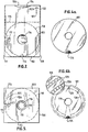
- FIG. 1 shows an exploded view of a three-part system embodying the principles of the present invention. Like components have identical numbers in the subsequent figures.
- Fig. 1 shows two envelope portions, one designated an "inner” envelope 102, and one designated an “outer” envelope 103. Both are rectangular in configura-tion, with the inner envelope 102 having respective “short” sides 104 and 106, and respective "long” sides 105 and 107.
- outer envelope 103 has "long" sides 108 and 111 and "short” sides 109 and 112.
- the inner envelope 102 is closed on the long sides 105 and 107 and on the top short side 106, but is open on the lower short side 104, advantageously defining an opening for the full extremity of short side 104.
- Outer envelope 103 is closed on long sides 108 and 111 and on the lower short side 112, but is open on top short side 109, preferably for the full extremity of that short side.
- the inner envelope 102 is adapted to nest completely within the outer envelope 103, with the opening on side 104 within and at the bottom of envelope 103 (i.e. "an inverted nested relationship" or "inversely nesting").
- envelopes 102 and 103 are to carry an element of photographic film prior to exposure and also subsequent to exposure but prior to development, a close-fitting nested relationship is desirable, with the inner envelope 102 having dimensions which are close fitting within envelope 103, but which allow relatively free, unbinding sliding movement therewithin, for easy forced withdrawal of envelope 102, from envelope 103. Further, it is preferable that both envelopes 102 and 103 be made of heavy, opaque material to prevent spurious exposure of the photo-graphic medium therewithin.
- a disk 101 which has an opening 119 at its center and which includes an appropriate section of photographic medium for exposure, development, and subsequent display of relevant information in the form of sequentially associated images.
- the disk 101 has at least a portion of an annulus 118, defined in Fig. 1 by an inner radius 120 and the outer radius of the disk 101, which is of photo- graphic medium.
- the entire such annulus is of photographic medium and occurs about the circumference of the disk 101, and in a preferred embodiment the entire disk 101 is made of conventional commercially available X-ray type film.
- the disk 101 is carried within inner envelope 102, being inserted therein through opening 104.
- the disk 101 is approximately 8 inches in diameter, and the envelope 102 is slightly larger than that in order to accommodate free passage of the disk into and out of the inner envelope 102, yet to maintain it in fairly fixed position.
- an optional but preferred stop 127 is provided, above the open short side 104 by slightly more than the diameter of the disk, to fix the position of the disk within envelope 102.
- the stop 127 is achieved by a bonding of corresponding opposite sides of the envelope 102. As may be most clearly noted from Fig.
- the inner envelope 102 defines a recess 113 along the lower, open side 104, to permit, as disclosed hereinafter, careful removal of the disk from the inner envelope 102.
- the inner envelope 102 With the disk 101 carried in the inner envelope 102, the inner envelope 102 is inversely nested within outer envelope 103.
- outer envelope 103 defines a recess 114 along the top edge. As may be seen from Fig. 2, a portion of edge 106 of envelope 102 thereby is exposed for easy grasping and withdrawal.
- the outer envelope 103 also has a perforation 115 thereacross, which is described hereinafter, and openings 116 and 117.
- the openings 116 and 117 relate to film exposure and display, as described heeinafter, and as shown in Fig. 2, the openings 116 and 117 are filled by the inner envelope 102 when the three-part system is nested as shown in Fig. 2.
- a string or the like material 121 is connected both to the inner portion of outer envelope 103 at point 122, and to the outer portion of inner envelope 102 at point 123.
- the string 121 functions to limit the extent of travel of inner envelope 102 upon withdrawal from outer envelope 103, as shown in Fig. 3. It will be evident that alternative means may be employed, rather than a string 121, which serve similarly to limit the travel of withdrawal of inner envelope 102 from outer envelope 103 (e.g. folds, tabs, etc).
- the composite system including film disk 101, inner envelope 102, and outer envelope 103, when assembled such as shown in Fig. 2, protects the disk 101 from physical damage and from spurious exposure prior to exposure and development, when and as desired.
- a camera mechanism which is adapted to receive the composite system as shown in Fig. 2 in a substantially dark environment, whereby portions of the film which are to be exposed through recess 117 of envelope 103 (upon removal of inner envelope 102) will photographically imprint the disk 101.
- Many such systems are more or less conventional in cameras of known pedigree, and adaptation thereof to embodiments of the present invention is readily within the ability of those of ordinary skill in the art.
- exposure may commence, with the disk 101 being grasped generally in its center area, through void 116 of the outer envelope 103, and rotated thereabout. In this fashion, the outer periphery of the disk 101 will be incrementally passed through the void 117 of envelope 103. During such incremental rotation, sequential images, such as of adjacent cross sectional areas of an organ, may be transferred to the disk, a picture at a time.
- FIG. 4A shows an undeveloped disk, with an exposed area 124 being formed on the disk 101 during the initial system assembly process, by virtue of the recess 113 at the bottom of inner envelope 102.
- This exposed area 124 forms a convenient reference point on the disk 101 with respect to which the individual sequentially associated images may be transferred to the disk.
- Fig. 4B a disk is shown with pictures developed thereon.
- the disk 101 includes an outer ring of images 125 and an inner ring of images 126, suitably sequentially arrayed relative to the reference exposure area 124.
- the outer ring may depict one series of images (e.g. cross sections of the right breast), whereas the inner ring may include a corresponding alternative series of images (e.g. cross sections of the left breast). It will be apparent that depending upon the application, numerous sequences of images or photos may be utilized in a desired number of concentric rings about the center 119 of the disk 101.
- a sequence of exposures will be transferred to the disk 101 to result in a configuration as shown in Fig. 4B.
- the inner envelope is downwardly pushed to its original inverted nested position within outer envelope 103, as shown in Fig. 2.
- the film pack is suitably conveyed to a place for development, whereby the photos or images to which disk 101 has been exposed, are permanently developed thereon.
- the inner envelope 102 may be discarded, of course entailing removal of the string 121 as well.
- the outer envelope may be torn across perforation 115, yielding a permanent storage record as shown in Fig. 5, with the foreshortened outer envelope 103 remaining, and the developed disk 101 stored therein, and with image series 125 and 126 being serially presented through the opening 117 as the entire disk 101 is rotated about its center of rotation.
Landscapes
- Physics & Mathematics (AREA)
- General Physics & Mathematics (AREA)
- Silver Salt Photography Or Processing Solution Therefor (AREA)
- Thermal Transfer Or Thermal Recording In General (AREA)
- Packaging Of Annular Or Rod-Shaped Articles, Wearing Apparel, Cassettes, Or The Like (AREA)
- Radiography Using Non-Light Waves (AREA)
- Combination Of More Than One Step In Electrophotography (AREA)
- Ultra Sonic Daignosis Equipment (AREA)
- Sheet Holders (AREA)
- Television Signal Processing For Recording (AREA)
Abstract
Description
- This invention relates to image storage and retrieval, and more particularly to disk style systems for recording and storage of sequentially associated photographic images such as from clinical, diagnostic, and medical screening systems.
- Many researchers in diagnostic imaging and screening fields have voiced concern that as the technological capabilities of various methods improve, the sheer volume of data produced will become overwhelming, dangerously near the point at which retrieval and evaluation, rather than imaging resolution and effectiveness, are the critical parameters. For example, presently the field of ultrasound diagnostic imaging is being successfully applied to the field of breast scanning. Resolutions in the range of 1 millimeter are realistic, yielding tremendous diagnostic capacity but further requiring as many as 100 images needed fully to scan a breast. When it is contemplated that screening centers will process hundreds of patients each day, it becomes evident that the technological capabilities to display detail will far outstrip the clinician's ability to appreciate it.
- Accordingly, it is an object of the present invention to provide image storage and display systems which permit convenient and highly accessible storage facility.
- Inevitably, mass screening instruments and programs, such as ultrasound breast screening programs, are falling with the gambit of responsibility of hospital radiology departments. Such departments, of course, have through the years developed considerable expertise in photographic information systems, and have committed themselves to substantial expenditures in the areas of developing, cataloging, and storing records, such as X-ray packs.
- It is an associated object of the present invention to utilize established technologies and procedures of information storage which have found widespread acceptance in conjunction with X-ray technology. As associated objects, photographic images are to be obtained with a relative maximum of simplicity and security with respect to the photographic medium during the photographing process, en route to development facilities, and in preparation for development. Furthermore, it is an object that substantial portions of the system be retained as permanent file jackets, records, and entries once the photographic exposure, development, and completion processes are achieved. These objects are attained by the features of claim 1.
- The present invention incorporates photo- graphic disk and multiple part nesting envelope systems whereby undeveloped film is safely secured, and the disk is conveniently exposed for information gathering purposes yet is securely conveyed for development, and wherein the same envelope system may be utilized as a combination storage file and display carrier module.
- In accordance with the principles of the present invention, a disk of film in the range of 8 inches in diameter is adapted to receive multiple, sequentially associated images about its periphery. The film disk is adapted to be carried within a pair of inversely nesting envelopes (i.e. the open side of one deepest in the closed side of the other). The inner envelope is solid and opaque but for a recess at its lower, open end, which thereby exposes a corresponding tab area of the disk therewithin. The outer envelope has a recess at its top open end for withdrawal of the inner envelope, and has holes or voids at its lower part, one in the center surrounding the center of the disk, another at an outer periphery to enable sequential image exposures on the disk. The developed tab portion serves as a start/stop reference.
- Upon completion of the development of the exposed images on the disk, the inner envelope is discarded and the outer envelope is foreshortened to the size necessary for enclosure of the disk. In turn, the foreshortened outer envelope constitutes a storage file which protects the disk, and also serves as a cartridge for mounting the disk in a suitable display apparatus.
- Fig. 1 shows a detached, three-part system embodying the principles of the present invention, including a disk and two envelope portions;
- Figs. 2 and 3 show respective orientations or combinations of the three parts of the system,
- Fig. 2 representing storage prior to development, and Fig. 3 representing positioning exposure of the disk;
- Figs. 4A and 4B show views of the disk prior to and subsequent to development of images thereon; and
- Fig. 5 shows a disk and envelope combination cartridge, subsequent to development, for storage and display as desired.
- Referring first to Fig. 1, there is shown an exploded view of a three-part system embodying the principles of the present invention. Like components have identical numbers in the subsequent figures. Fig. 1 shows two envelope portions, one designated an "inner"
envelope 102, and one designated an "outer"envelope 103. Both are rectangular in configura-tion, with theinner envelope 102 having respective "short"sides sides outer envelope 103 has "long"sides sides inner envelope 102 is closed on thelong sides short side 106, but is open on the lowershort side 104, advantageously defining an opening for the full extremity ofshort side 104.Outer envelope 103 is closed onlong sides short side 112, but is open on topshort side 109, preferably for the full extremity of that short side. Theinner envelope 102 is adapted to nest completely within theouter envelope 103, with the opening onside 104 within and at the bottom of envelope 103 (i.e. "an inverted nested relationship" or "inversely nesting"). Inasmuch as theenvelopes inner envelope 102 having dimensions which are close fitting withinenvelope 103, but which allow relatively free, unbinding sliding movement therewithin, for easy forced withdrawal ofenvelope 102, fromenvelope 103. Further, it is preferable that bothenvelopes - As shown in Fig. 1 is a
disk 101 which has anopening 119 at its center and which includes an appropriate section of photographic medium for exposure, development, and subsequent display of relevant information in the form of sequentially associated images. Thedisk 101 has at least a portion of anannulus 118, defined in Fig. 1 by an inner radius 120 and the outer radius of thedisk 101, which is of photo- graphic medium. Preferably, the entire such annulus is of photographic medium and occurs about the circumference of thedisk 101, and in a preferred embodiment theentire disk 101 is made of conventional commercially available X-ray type film. - In a preferred construction, the composite of which is shown in Fig. 2, the
disk 101 is carried withininner envelope 102, being inserted therein throughopening 104. In a preferred embodiment, thedisk 101 is approximately 8 inches in diameter, and theenvelope 102 is slightly larger than that in order to accommodate free passage of the disk into and out of theinner envelope 102, yet to maintain it in fairly fixed position. To facilitate such positioning, an optional but preferred stop 127 is provided, above the openshort side 104 by slightly more than the diameter of the disk, to fix the position of the disk withinenvelope 102. In a preferred embodiment, the stop 127 is achieved by a bonding of corresponding opposite sides of theenvelope 102. As may be most clearly noted from Fig. 1, theinner envelope 102 defines arecess 113 along the lower,open side 104, to permit, as disclosed hereinafter, careful removal of the disk from theinner envelope 102. With thedisk 101 carried in theinner envelope 102, theinner envelope 102 is inversely nested withinouter envelope 103. For purposes of subsequent withdrawal of theinner envelope 102,outer envelope 103 defines arecess 114 along the top edge. As may be seen from Fig. 2, a portion ofedge 106 ofenvelope 102 thereby is exposed for easy grasping and withdrawal. Theouter envelope 103 also has aperforation 115 thereacross, which is described hereinafter, andopenings - The
openings openings inner envelope 102 when the three-part system is nested as shown in Fig. 2. Also as shown in Fig. 2, during the assembly process, a string or thelike material 121 is connected both to the inner portion ofouter envelope 103 atpoint 122, and to the outer portion ofinner envelope 102 atpoint 123. Thestring 121 functions to limit the extent of travel ofinner envelope 102 upon withdrawal fromouter envelope 103, as shown in Fig. 3. It will be evident that alternative means may be employed, rather than astring 121, which serve similarly to limit the travel of withdrawal ofinner envelope 102 from outer envelope 103 (e.g. folds, tabs, etc). - Accordingly, as shown in Fig. 2, the composite system including
film disk 101,inner envelope 102, andouter envelope 103, when assembled such as shown in Fig. 2, protects thedisk 101 from physical damage and from spurious exposure prior to exposure and development, when and as desired. - It is anticipated that in utilization of the principles of the present invention, there will be provided a camera mechanism which is adapted to receive the composite system as shown in Fig. 2 in a substantially dark environment, whereby portions of the film which are to be exposed through
recess 117 of envelope 103 (upon removal of inner envelope 102) will photographically imprint thedisk 101. Many such systems are more or less conventional in cameras of known pedigree, and adaptation thereof to embodiments of the present invention is readily within the ability of those of ordinary skill in the art. Once the Fig. 2 system is inserted into a suitable slot or position for exposure, theinner envelope 102 is partially upwardly withdrawn, as shown in Fig. 3, by the simple expediency of graspinginner envelope 102 at the position ofvoid 114 inouter envelope 103. It is noted that suitable simultaneous pressure then applied toouter envelope 103 in the region overlyingrecess 113 of the inner envelope. 102, whether manually or automatically applied, will result in thedisk 101 being held in place in the bottom portion ofouter envelope 103, as shown in Fig. 3, it being understood that at that time the mechanism is within the camera and the.disk 101 is not being exposed to ambient or spurious light. As noted in Fig. 3, thestring 121 is then extended to its limits, thereby correspondingly to limit the amount of travel of theinner envelope 102 with an upper portion of thedisk 101 still nested within the lower extremities ofinner envelope 102. In this fashion, once the exposure process has been completed,inner envelope 102 may be pushed downwardly once more to enclosedisk 101 as shown in Fig. 2, for security between the time of exposure and time of development of the film portion ofdisk 101. - As the system is held in the camera apparatus in the positioning shown in Fig. 3, exposure may commence, with the
disk 101 being grasped generally in its center area, throughvoid 116 of theouter envelope 103, and rotated thereabout. In this fashion, the outer periphery of thedisk 101 will be incrementally passed through thevoid 117 ofenvelope 103. During such incremental rotation, sequential images, such as of adjacent cross sectional areas of an organ, may be transferred to the disk, a picture at a time. - Referring briefly to Figs. 4A and 4B, this sequential exposure of the
disk 101 may perhaps be better understood. Fig. 4A shows an undeveloped disk, with an exposedarea 124 being formed on thedisk 101 during the initial system assembly process, by virtue of therecess 113 at the bottom ofinner envelope 102. This exposedarea 124 forms a convenient reference point on thedisk 101 with respect to which the individual sequentially associated images may be transferred to the disk. Referring to Fig. 4B, a disk is shown with pictures developed thereon. In a preferred embodiment, thedisk 101 includes an outer ring ofimages 125 and an inner ring ofimages 126, suitably sequentially arrayed relative to thereference exposure area 124. Conveniently, then, the outer ring may depict one series of images (e.g. cross sections of the right breast), whereas the inner ring may include a corresponding alternative series of images (e.g. cross sections of the left breast). It will be apparent that depending upon the application, numerous sequences of images or photos may be utilized in a desired number of concentric rings about thecenter 119 of thedisk 101. - Returning, then, to Fig. 3, it will be understood that within the camera, a sequence of exposures will be transferred to the
disk 101 to result in a configuration as shown in Fig. 4B. Thereupon, the inner envelope is downwardly pushed to its original inverted nested position withinouter envelope 103, as shown in Fig. 2. Thereupon, the film pack is suitably conveyed to a place for development, whereby the photos or images to whichdisk 101 has been exposed, are permanently developed thereon. - After the
disk 101 is developed, theinner envelope 102 may be discarded, of course entailing removal of thestring 121 as well. For purposes of convenience, the outer envelope may be torn acrossperforation 115, yielding a permanent storage record as shown in Fig. 5, with the foreshortenedouter envelope 103 remaining, and thedeveloped disk 101 stored therein, and withimage series opening 117 as theentire disk 101 is rotated about its center of rotation. - It is to be understood that the foregoing sets forth preferred and illustrative embodiments of the principles of the present invention, but that numerous alternatives will occur to those of ordinary skill in the art without departure from the spirit or scope of the principles of the present invention.
Claims (6)
Priority Applications (1)
| Application Number | Priority Date | Filing Date | Title |
|---|---|---|---|
| AT80303762T ATE4252T1 (en) | 1979-10-24 | 1980-10-23 | STORAGE AND RECORDING SYSTEM FOR A LARGE SET OF ASSOCIATED IMAGES. |
Applications Claiming Priority (2)
| Application Number | Priority Date | Filing Date | Title |
|---|---|---|---|
| US8784979A | 1979-10-24 | 1979-10-24 | |
| US87849 | 1979-10-24 |
Publications (2)
| Publication Number | Publication Date |
|---|---|
| EP0028134A1 EP0028134A1 (en) | 1981-05-06 |
| EP0028134B1 true EP0028134B1 (en) | 1983-07-20 |
Family
ID=22207615
Family Applications (1)
| Application Number | Title | Priority Date | Filing Date |
|---|---|---|---|
| EP80303762A Expired EP0028134B1 (en) | 1979-10-24 | 1980-10-23 | Storage and record system for a large number of associated images |
Country Status (6)
| Country | Link |
|---|---|
| EP (1) | EP0028134B1 (en) |
| JP (1) | JPS5667839A (en) |
| AT (1) | ATE4252T1 (en) |
| AU (1) | AU534985B2 (en) |
| CA (1) | CA1163128A (en) |
| DE (1) | DE3064311D1 (en) |
Family Cites Families (6)
| Publication number | Priority date | Publication date | Assignee | Title |
|---|---|---|---|---|
| DE826692C (en) * | 1949-05-21 | 1952-01-03 | Andre Victor Leon Clement Debr | Movie cassette |
| US3536276A (en) * | 1967-06-05 | 1970-10-27 | Eastman Kodak Co | Cartridge for reel of strip material |
| US3617013A (en) * | 1969-06-27 | 1971-11-02 | Eastman Kodak Co | Cartridge |
| DE2204321A1 (en) * | 1972-01-31 | 1973-08-09 | Guenter Tetzlaff | RECORD CASSETTE |
| US4000232A (en) * | 1975-09-23 | 1976-12-28 | Mobil Oil Corporation | Method of pelletizing plastic material |
| US4168888A (en) * | 1978-01-09 | 1979-09-25 | Visual Data Corporation | Film cartridge |
-
1980
- 1980-10-17 AU AU63475/80A patent/AU534985B2/en not_active Ceased
- 1980-10-22 CA CA000363002A patent/CA1163128A/en not_active Expired
- 1980-10-23 AT AT80303762T patent/ATE4252T1/en not_active IP Right Cessation
- 1980-10-23 JP JP14765080A patent/JPS5667839A/en active Pending
- 1980-10-23 DE DE8080303762T patent/DE3064311D1/en not_active Expired
- 1980-10-23 EP EP80303762A patent/EP0028134B1/en not_active Expired
Also Published As
| Publication number | Publication date |
|---|---|
| AU534985B2 (en) | 1984-02-23 |
| AU6347580A (en) | 1981-04-30 |
| ATE4252T1 (en) | 1983-08-15 |
| CA1163128A (en) | 1984-03-06 |
| EP0028134A1 (en) | 1981-05-06 |
| JPS5667839A (en) | 1981-06-08 |
| DE3064311D1 (en) | 1983-08-25 |
Similar Documents
| Publication | Publication Date | Title |
|---|---|---|
| US4411360A (en) | Storage and record system for a large number of associated images | |
| US4896027A (en) | Portable detachable data record | |
| US4928298A (en) | Information-bearing sheet for X-ray film | |
| US5709496A (en) | Apparatus for storing film cartridge and proofs | |
| US5251747A (en) | Storage assemblage for index print sheets and cassettes | |
| US5251745A (en) | Container for index print sheet and cassette | |
| US5303825A (en) | Storage assemblage for index print sheets and cassettes | |
| JPH01279250A (en) | Cartridge for preserving film | |
| EP0546072A1 (en) | Marked x-ray film with modified cassette for identifying the exposure side of a medical radiograph | |
| EP0028134A1 (en) | Storage and record system for a large number of associated images | |
| US3371208A (en) | X-ray film cassette having means for removing the films while maintaining a light-tight condition | |
| US3325642A (en) | Diffusion transfer printing of electron micrographs and envelope therefor | |
| US5627354A (en) | System for handling sheet film | |
| Nayler | A clinical image library using photo CD | |
| GB2203699A (en) | Portable detachable data record | |
| CN2290872Y (en) | Directly recording magazine | |
| JP3345864B2 (en) | Cartridge storage album | |
| CA1249745A (en) | Information-bearing sheet for x-ray film | |
| Kolodny et al. | Eight years' experience with a filmless all-digital nuclear medicine department | |
| JPH02171297A (en) | Printing device for film storage cartridge and film storage cartridge | |
| JP2002202571A (en) | Radiation cassette | |
| JP3003859U (en) | Photo film organizer | |
| Venot et al. | Improvement of dynamic cholescintigraphy through mathematical modelling of Tc-99m-diethyl IDA pharmacokinetics | |
| Shibata | Performance test on polaroid films | |
| US595551A (en) | Photographic camera |
Legal Events
| Date | Code | Title | Description |
|---|---|---|---|
| PUAI | Public reference made under article 153(3) epc to a published international application that has entered the european phase |
Free format text: ORIGINAL CODE: 0009012 |
|
| AK | Designated contracting states |
Designated state(s): AT BE CH DE FR GB IT NL SE |
|
| 17P | Request for examination filed |
Effective date: 19811014 |
|
| GRAA | (expected) grant |
Free format text: ORIGINAL CODE: 0009210 |
|
| AK | Designated contracting states |
Designated state(s): AT BE CH DE FR GB IT LI NL SE |
|
| PG25 | Lapsed in a contracting state [announced via postgrant information from national office to epo] |
Ref country code: IT Free format text: LAPSE BECAUSE OF FAILURE TO SUBMIT A TRANSLATION OF THE DESCRIPTION OR TO PAY THE FEE WITHIN THE PRESCRIBED TIME-LIMIT;WARNING: LAPSES OF ITALIAN PATENTS WITH EFFECTIVE DATE BEFORE 2007 MAY HAVE OCCURRED AT ANY TIME BEFORE 2007. THE CORRECT EFFECTIVE DATE MAY BE DIFFERENT FROM THE ONE RECORDED. Effective date: 19830720 |
|
| REF | Corresponds to: |
Ref document number: 4252 Country of ref document: AT Date of ref document: 19830815 Kind code of ref document: T |
|
| REF | Corresponds to: |
Ref document number: 3064311 Country of ref document: DE Date of ref document: 19830825 |
|
| ET | Fr: translation filed | ||
| PLBE | No opposition filed within time limit |
Free format text: ORIGINAL CODE: 0009261 |
|
| STAA | Information on the status of an ep patent application or granted ep patent |
Free format text: STATUS: NO OPPOSITION FILED WITHIN TIME LIMIT |
|
| 26N | No opposition filed | ||
| PGFP | Annual fee paid to national office [announced via postgrant information from national office to epo] |
Ref country code: FR Payment date: 19841026 Year of fee payment: 5 |
|
| PGFP | Annual fee paid to national office [announced via postgrant information from national office to epo] |
Ref country code: CH Payment date: 19841029 Year of fee payment: 5 |
|
| PGFP | Annual fee paid to national office [announced via postgrant information from national office to epo] |
Ref country code: DE Payment date: 19841102 Year of fee payment: 5 |
|
| PGFP | Annual fee paid to national office [announced via postgrant information from national office to epo] |
Ref country code: SE Payment date: 19841231 Year of fee payment: 5 Ref country code: BE Payment date: 19841231 Year of fee payment: 5 |
|
| PGFP | Annual fee paid to national office [announced via postgrant information from national office to epo] |
Ref country code: AT Payment date: 19851021 Year of fee payment: 6 |
|
| PGFP | Annual fee paid to national office [announced via postgrant information from national office to epo] |
Ref country code: NL Payment date: 19851031 Year of fee payment: 6 |
|
| PG25 | Lapsed in a contracting state [announced via postgrant information from national office to epo] |
Ref country code: AT Effective date: 19861023 |
|
| PG25 | Lapsed in a contracting state [announced via postgrant information from national office to epo] |
Ref country code: SE Effective date: 19861024 |
|
| PG25 | Lapsed in a contracting state [announced via postgrant information from national office to epo] |
Ref country code: LI Effective date: 19861031 Ref country code: CH Effective date: 19861031 Ref country code: BE Effective date: 19861031 |
|
| BERE | Be: lapsed |
Owner name: TECHNICARE CORP. Effective date: 19861031 |
|
| PG25 | Lapsed in a contracting state [announced via postgrant information from national office to epo] |
Ref country code: NL Effective date: 19870501 |
|
| NLV4 | Nl: lapsed or anulled due to non-payment of the annual fee | ||
| PG25 | Lapsed in a contracting state [announced via postgrant information from national office to epo] |
Ref country code: FR Free format text: LAPSE BECAUSE OF NON-PAYMENT OF DUE FEES Effective date: 19870630 |
|
| REG | Reference to a national code |
Ref country code: CH Ref legal event code: PL |
|
| GBPC | Gb: european patent ceased through non-payment of renewal fee | ||
| PG25 | Lapsed in a contracting state [announced via postgrant information from national office to epo] |
Ref country code: DE Effective date: 19870701 |
|
| REG | Reference to a national code |
Ref country code: FR Ref legal event code: ST |
|
| PG25 | Lapsed in a contracting state [announced via postgrant information from national office to epo] |
Ref country code: GB Effective date: 19881118 |
|
| EUG | Se: european patent has lapsed |
Ref document number: 80303762.1 Effective date: 19870811 |