EP0027770A1 - Method of constructing a ball joint and fixture for use in that method - Google Patents
Method of constructing a ball joint and fixture for use in that method Download PDFInfo
- Publication number
- EP0027770A1 EP0027770A1 EP80401502A EP80401502A EP0027770A1 EP 0027770 A1 EP0027770 A1 EP 0027770A1 EP 80401502 A EP80401502 A EP 80401502A EP 80401502 A EP80401502 A EP 80401502A EP 0027770 A1 EP0027770 A1 EP 0027770A1
- Authority
- EP
- European Patent Office
- Prior art keywords
- ball
- housing
- bearing material
- cavity
- fixture
- Prior art date
- Legal status (The legal status is an assumption and is not a legal conclusion. Google has not performed a legal analysis and makes no representation as to the accuracy of the status listed.)
- Withdrawn
Links
Images
Classifications
-
- B—PERFORMING OPERATIONS; TRANSPORTING
- B29—WORKING OF PLASTICS; WORKING OF SUBSTANCES IN A PLASTIC STATE IN GENERAL
- B29C—SHAPING OR JOINING OF PLASTICS; SHAPING OF MATERIAL IN A PLASTIC STATE, NOT OTHERWISE PROVIDED FOR; AFTER-TREATMENT OF THE SHAPED PRODUCTS, e.g. REPAIRING
- B29C45/00—Injection moulding, i.e. forcing the required volume of moulding material through a nozzle into a closed mould; Apparatus therefor
- B29C45/14—Injection moulding, i.e. forcing the required volume of moulding material through a nozzle into a closed mould; Apparatus therefor incorporating preformed parts or layers, e.g. injection moulding around inserts or for coating articles
- B29C45/14754—Injection moulding, i.e. forcing the required volume of moulding material through a nozzle into a closed mould; Apparatus therefor incorporating preformed parts or layers, e.g. injection moulding around inserts or for coating articles being in movable or releasable engagement with the coating, e.g. bearing assemblies
-
- C—CHEMISTRY; METALLURGY
- C08—ORGANIC MACROMOLECULAR COMPOUNDS; THEIR PREPARATION OR CHEMICAL WORKING-UP; COMPOSITIONS BASED THEREON
- C08F—MACROMOLECULAR COMPOUNDS OBTAINED BY REACTIONS ONLY INVOLVING CARBON-TO-CARBON UNSATURATED BONDS
- C08F6/00—Post-polymerisation treatments
- C08F6/06—Treatment of polymer solutions
- C08F6/12—Separation of polymers from solutions
-
- F—MECHANICAL ENGINEERING; LIGHTING; HEATING; WEAPONS; BLASTING
- F16—ENGINEERING ELEMENTS AND UNITS; GENERAL MEASURES FOR PRODUCING AND MAINTAINING EFFECTIVE FUNCTIONING OF MACHINES OR INSTALLATIONS; THERMAL INSULATION IN GENERAL
- F16C—SHAFTS; FLEXIBLE SHAFTS; ELEMENTS OR CRANKSHAFT MECHANISMS; ROTARY BODIES OTHER THAN GEARING ELEMENTS; BEARINGS
- F16C11/00—Pivots; Pivotal connections
- F16C11/04—Pivotal connections
- F16C11/06—Ball-joints; Other joints having more than one degree of angular freedom, i.e. universal joints
- F16C11/0619—Ball-joints; Other joints having more than one degree of angular freedom, i.e. universal joints the female part comprising a blind socket receiving the male part
- F16C11/0623—Construction or details of the socket member
- F16C11/0628—Construction or details of the socket member with linings
- F16C11/0633—Construction or details of the socket member with linings the linings being made of plastics
-
- Y—GENERAL TAGGING OF NEW TECHNOLOGICAL DEVELOPMENTS; GENERAL TAGGING OF CROSS-SECTIONAL TECHNOLOGIES SPANNING OVER SEVERAL SECTIONS OF THE IPC; TECHNICAL SUBJECTS COVERED BY FORMER USPC CROSS-REFERENCE ART COLLECTIONS [XRACs] AND DIGESTS
- Y10—TECHNICAL SUBJECTS COVERED BY FORMER USPC
- Y10T—TECHNICAL SUBJECTS COVERED BY FORMER US CLASSIFICATION
- Y10T29/00—Metal working
- Y10T29/49—Method of mechanical manufacture
- Y10T29/49636—Process for making bearing or component thereof
- Y10T29/49643—Rotary bearing
- Y10T29/49647—Plain bearing
- Y10T29/49648—Self-adjusting or self-aligning, including ball and socket type, bearing and component making
- Y10T29/49657—Socket making
- Y10T29/49659—Socket making by molding or casting
-
- Y—GENERAL TAGGING OF NEW TECHNOLOGICAL DEVELOPMENTS; GENERAL TAGGING OF CROSS-SECTIONAL TECHNOLOGIES SPANNING OVER SEVERAL SECTIONS OF THE IPC; TECHNICAL SUBJECTS COVERED BY FORMER USPC CROSS-REFERENCE ART COLLECTIONS [XRACs] AND DIGESTS
- Y10—TECHNICAL SUBJECTS COVERED BY FORMER USPC
- Y10T—TECHNICAL SUBJECTS COVERED BY FORMER US CLASSIFICATION
- Y10T29/00—Metal working
- Y10T29/49—Method of mechanical manufacture
- Y10T29/49826—Assembling or joining
- Y10T29/49885—Assembling or joining with coating before or during assembling
Definitions
- This invention relates to a method of constructing a ball joint and to a fixture for use in that method.
- Ball joints are well known in the art and usually comprise a ball on the end of a stud or shank (commonly referred to as a "ball stud") which is received in a cavity or socket in a housing and supported by a resilient bearing member also received in the cavity.
- a typical ball joint such as is disclosed in U. S. Patent N° 3,679,248, is constructed as follows :First, the bearing member, the ball stud, and the housing are separately formed and machined. Second, the ball end of the stud is inserted into the bearing member. The ball and bearing member are then pressed into the machined socket in the ball joint housing. Finally, a retaining ring is attached to the housing or the housing is deformed or crimped to hold the ball and bearing within the housing. This method requires precision machining of the mating surfaces of the bearing member and of the housing separately so that the bearing member may be pressed into the housing without destroying the bearing member and so that the bearing member is properly stressed so that a proper load is maintained on the ball.
- An advantage of this method is that a single socket can be used with ball studs of various sizes since the bearing material must necessarily conform to the space between the assembled ball and housing.
- a further advantage of this invention is that, since the bearing surface is formed while in contact with the ball, the bearing material has a long wearing bearing surface which is closely matched to that of the ball.
- Another advantage of this invention is that there is provided a single fixture which positions the ball in the ball joint socket and which seals between the ball stud and the socket housing so that a plastic bearing material may be injected into the cavity between the ball stud and the socket housing and held under pressure.
- a ball joint assembly 10 manufactured pursuant to the present invention includes a finished housing 12 which receives a ball-ended stud 14 and a bearing 16.
- a retaining ring 18 holds the ball-ended stud 14 and the bearing 16 within the housing 12.
- Applicant's method of constructing this ball joint includes forming a housing blank 20 with a substantially spherical cavity 22 and with a ball-receiving of open end 23 formed therein as shown in Figure 2.
- the blank 20 may be formed by hot forming, cold impact, powdered metal, impact extruding, or any other suitable process.
- the cavity 22 need not be machined to close tolerances since the surface of the housing which defines the cavity 22 is not used as a ball engaging bearing surface in the completed ball joint 10.
- the outer and inner surfaces of the blank 20 may be machined as desired as shown in Figure 3.
- retaining ring groove 26 may be machined on the outer surface of blank 20.
- bearing material retaining groove 28, retaining ring groove 30 and chamber 32 may be machined on the inner surfaces of housing blank 20.
- the housing blank 20 is provided with a bore 34 through which bearing material 14 may later be injected.
- Positioning fixture 40 may be used to hold the ball 36 in the desired spaced position within cavity 22 as is also illustrated in Figure 4.
- Positioning fixture 40 includes a housing engaging portion 42, which may be adapted to mate with retaining ring groove 30.
- Positioning fixture 40 also includes a ball engaging portion 44.
- Portions 42 and 44 are adapted to cooperate with the housing 12 and-the ball 36 to maintain the ball 36 in the desired spaced position within housing 12.
- Portions 42 and 44 of fixture 40 are also adapted to sealingly engage both the housing 12 and the ball 36 so that bearing material injected into the space between the ball and the housing may be pressurized.
- a clamping force may be applied to hous-12 and fixture 40 so that shoulder 46 of housing 12 seats tightly against shoulder 48 of fixture housing engaging portion 42.
- a suitable injection fitting 56 is then fitted into passage 34.
- Plastic bearing material 16 such as the thermo plastic material used in typical prior art ball joints, is then injected through passage 34 to fill the space between ball 36 and housing 12, as shown in Figure 4.
- the injected bearing material 16 is then allowed to congeal or harden under pressure while in contact with the ball 36 in the cavity 22.
- the seal between ball 36, fixture 40 and housing 12 may be maintained as the bearing material 16 congeals so that, due to the pressurization of the bearing material 16, the congealed bearing material 16 applies a preload to ball 36 in cavity 22 in the finished ball joint 10. It may also be desirable to rotate ball 36 as the bearing material 16 congeals so that the bearing material 16 forms a smooth bearing surface adjacent ball 36.
- the congealed bearing material 16 cooperates with retaining groove 28 to aid in holding the bearing material 16 within cavity 22.
- the congealed bearing material 16 maintains ball 36 in the proper spaced position within cavity 22 while at the same time allowing free rotation of ball 36 within cavity 22.
- the preloaded bearing material 16 provides the ball joint 10 with a wear take-up capability.
- the positioning fixture 40 and the injection fixture 50 are removed after the bearing material 16 has congealed and a retaining ring 18 is press fitted into retaining groove 30 as shown in Figure 1.
- a single positioning fixture (not shown) may be adapted to simultaneously or sequentially position ball 36 within cavity 22 and also press retaining ring 18 into groove 30.
- the retaining ring 18 provides additional structural integrity to the assembled ball joint 10.
- Retaining ring 18 may include a bonded rubber boot 52 to prevent stud 37 from engaging retaining ring 18 as the ball 36 pivots and to protect the assembled ball joint from contamination.
Landscapes
- Engineering & Computer Science (AREA)
- Chemical & Material Sciences (AREA)
- Mechanical Engineering (AREA)
- General Engineering & Computer Science (AREA)
- Health & Medical Sciences (AREA)
- Chemical Kinetics & Catalysis (AREA)
- Medicinal Chemistry (AREA)
- Polymers & Plastics (AREA)
- Organic Chemistry (AREA)
- Manufacturing & Machinery (AREA)
- Pivots And Pivotal Connections (AREA)
Abstract
A method for constructing a ball joint includes the steps of positioning a ball (36) within a ball joint socket (12). Plastic-bearing material (16) is then allowed to congeal in the socket (12) while in contact with the ball (36). A positioning fixture (40) maintains the ball (36) in the desired spaced position in the socket (12) while also maintaining a seal between the ball (36) and the socket housing (12) so that the bearing material (16) may be pressurized as it congeals.
Description
- This invention relates to a method of constructing a ball joint and to a fixture for use in that method.
- Ball joints are well known in the art and usually comprise a ball on the end of a stud or shank (commonly referred to as a "ball stud") which is received in a cavity or socket in a housing and supported by a resilient bearing member also received in the cavity. A typical ball joint, such as is disclosed in U. S. Patent N° 3,679,248, is constructed as follows :First, the bearing member, the ball stud, and the housing are separately formed and machined. Second, the ball end of the stud is inserted into the bearing member. The ball and bearing member are then pressed into the machined socket in the ball joint housing. Finally, a retaining ring is attached to the housing or the housing is deformed or crimped to hold the ball and bearing within the housing. This method requires precision machining of the mating surfaces of the bearing member and of the housing separately so that the bearing member may be pressed into the housing without destroying the bearing member and so that the bearing member is properly stressed so that a proper load is maintained on the ball.
- It is an object of the present invention to provide a simpler and less expensive method than prior art methods of constructing ball joints and in which the number and complexity of housing and bearing machining steps is reduced.
- To this end the invention proposes :
- A method of constructing a ball joint characterized in that it comprises the steps of :
- - forming a ball-receiving cavity in a housing ;
- - positioning a ball within said cavity ;
- - injecting a plastic bearing material into said cavity between the ball and the walls of the cavity ; and
- - allowing said plastic bearing material to congeal in said cavity while holding said ball in contact with said bearing material.
- An advantage of this method is that a single socket can be used with ball studs of various sizes since the bearing material must necessarily conform to the space between the assembled ball and housing.
- A further advantage of this invention is that, since the bearing surface is formed while in contact with the ball, the bearing material has a long wearing bearing surface which is closely matched to that of the ball.
- Another advantage of this invention is that there is provided a single fixture which positions the ball in the ball joint socket and which seals between the ball stud and the socket housing so that a plastic bearing material may be injected into the cavity between the ball stud and the socket housing and held under pressure.
- The invention will now be described with reference to the accompanying drawings wherein :
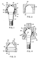
- - Figure 1 is a longitudinal cross-sectional view of a completed ball joint assembly manufactured according to the present invention ;
- - Figure 2 is a cross-sectional view of a ball joint housing blank with a ball-receiving cavity ;
- - Figure 3 is a cross-sectional view of a machined ball joint housing made from the blank illustrated in Figure 2 ;
- - Figure 4 is a cross-sectional view showing applicant's positioning fixture and an injection molding fixture along with the ball joint.
- Referring now to the drawing, a
ball joint assembly 10 manufactured pursuant to the present invention includes a finishedhousing 12 which receives a ball-endedstud 14 and abearing 16. Aretaining ring 18 holds the ball-endedstud 14 and the bearing 16 within thehousing 12. Applicant's method of constructing this ball joint includes forming a housing blank 20 with a substantiallyspherical cavity 22 and with a ball-receiving ofopen end 23 formed therein as shown in Figure 2. The blank 20 may be formed by hot forming, cold impact, powdered metal, impact extruding, or any other suitable process. Thecavity 22 need not be machined to close tolerances since the surface of the housing which defines thecavity 22 is not used as a ball engaging bearing surface in the completedball joint 10. The outer and inner surfaces of the blank 20 may be machined as desired as shown in Figure 3. For example, retainingring groove 26 may be machined on the outer surface of blank 20. Similarly, bearingmaterial retaining groove 28, retainingring groove 30 andchamber 32 may be machined on the inner surfaces of housing blank 20. Finally, the housing blank 20 is provided with abore 34 through which bearingmaterial 14 may later be injected. - The
ball 36 on the end ofstud 14 is-then inserted through theopen cavity end 23 and into a spaced position relative tohousing 12 withincavity 22, as shown in Figure 4. Positioningfixture 40 may be used to hold theball 36 in the desired spaced position withincavity 22 as is also illustrated in Figure 4. Positioningfixture 40 includes ahousing engaging portion 42, which may be adapted to mate withretaining ring groove 30. Positioningfixture 40 also includes aball engaging portion 44.Portions housing 12 and-theball 36 to maintain theball 36 in the desired spaced position withinhousing 12.Portions fixture 40 are also adapted to sealingly engage both thehousing 12 and theball 36 so that bearing material injected into the space between the ball and the housing may be pressurized. To aid in sealing betweenhousing 12 and housing engaging portion 42 a clamping force may be applied to hous-12 andfixture 40 so thatshoulder 46 ofhousing 12 seats tightly againstshoulder 48 of fixturehousing engaging portion 42. - A
suitable injection fitting 56 is then fitted intopassage 34. Plastic bearingmaterial 16, such as the thermo plastic material used in typical prior art ball joints, is then injected throughpassage 34 to fill the space betweenball 36 andhousing 12, as shown in Figure 4. The injected bearingmaterial 16 is then allowed to congeal or harden under pressure while in contact with theball 36 in thecavity 22. The seal betweenball 36,fixture 40 andhousing 12 may be maintained as the bearingmaterial 16 congeals so that, due to the pressurization of thebearing material 16, the congealed bearingmaterial 16 applies a preload toball 36 incavity 22 in the finishedball joint 10. It may also be desirable to rotateball 36 as the bearingmaterial 16 congeals so that the bearingmaterial 16 forms a smooth bearing surfaceadjacent ball 36. The congealed bearingmaterial 16 cooperates with retaininggroove 28 to aid in holding the bearingmaterial 16 withincavity 22. - The congealed bearing
material 16 maintainsball 36 in the proper spaced position withincavity 22 while at the same time allowing free rotation ofball 36 withincavity 22. The preloaded bearingmaterial 16 provides theball joint 10 with a wear take-up capability. - The
positioning fixture 40 and the injection fixture 50 are removed after the bearingmaterial 16 has congealed and aretaining ring 18 is press fitted into retaininggroove 30 as shown in Figure 1. A single positioning fixture (not shown) may be adapted to simultaneously or sequentiallyposition ball 36 withincavity 22 and also pressretaining ring 18 intogroove 30. Theretaining ring 18 provides additional structural integrity to the assembledball joint 10. Retainingring 18 may include a bondedrubber boot 52 to preventstud 37 from engaging retainingring 18 as theball 36 pivots and to protect the assembled ball joint from contamination. - It is possible to provide an alternate positioning fixture (not shown) which itself includes passages for introducing the plastic bearing material into the
cavity 22 and for simultaneously venting air from the cavity. With such a fixture,passage 34 in thehousing 12 could be eliminated.
Claims (8)
1. A method of constructing a ball joint, characterized in that it comprises the steps of :
- forming a ball-receiving cavity (22) in a housing (20) ;
- positioning a ball (36) within said cavity (22) ;
- injecting a plastic bearing material (22 ; and
- allowing said plastic bearing material (16) to congeal in said cavity (22) while holding said ball (36) in contact with said bearing material (16).
2. A method according to claim 1, characterized in that it further comprises the step of :
- forming a passage (34) in said housing (20) through which said bearing material (16) may be injected into said cavity.
3. A method according to claim 1, characterized in that it further comprises the step of :
- forming a bearing material (12) retaining groove (28) in the wall of said cacity prior to injection of said bearing material (16).
4. A method according to claim 1, characterized in that it further comprises the step of :
- maintaining a seal (40) between the ball (36) and the housing (20) as the bearing material (16) is injected into the cavity (22) so that the plastic bearing material may be pressurized.
5. A method according to claim 1, characterized in that it further comprises the step of :
- pressurizing the injected bearing material (16) so that the bearing material (16) congeals while under pressure.
6. A method according to claim 1, characterized in that it further comprises the step of :
- rotating said ball (36) in said cavity (22) as said bearing material (16) congeals.
7. A method according to claim 1, characterized in that it further comprises the step of :
- attaching a retaining ring (18) to said housing (20) to retain said ball (36) and said bearing material (10) in said housing cavity (22).
8. A fixture (40) for use in a method of constructing a ball joint comprising the steps of positioning a ball (36) within a housing cavity (22) as plastic-bearing material (16) is injected into and congealed in the cavity (22) between the housing (20) and a the ball (36), characterized in that the fixture comprises a body with a housing-engaging portion (42) and a ball-engaging portion (44), said portions cooperating to maintain said ball (36) in said cavity (22) in a spaced position relative to said housing (26), said portions also cooperating to form a seal between said housing (20) and said ball (36) so that said plastic-bearing material (16) may be pressurized within said cavity (22).
Applications Claiming Priority (2)
| Application Number | Priority Date | Filing Date | Title |
|---|---|---|---|
| US87597 | 1979-10-22 | ||
| US06/087,597 US4290181A (en) | 1979-10-22 | 1979-10-22 | Ball joint forming method and apparatus therefor |
Publications (1)
| Publication Number | Publication Date |
|---|---|
| EP0027770A1 true EP0027770A1 (en) | 1981-04-29 |
Family
ID=22206138
Family Applications (1)
| Application Number | Title | Priority Date | Filing Date |
|---|---|---|---|
| EP80401502A Withdrawn EP0027770A1 (en) | 1979-10-22 | 1980-10-22 | Method of constructing a ball joint and fixture for use in that method |
Country Status (3)
| Country | Link |
|---|---|
| US (1) | US4290181A (en) |
| EP (1) | EP0027770A1 (en) |
| JP (1) | JPS5666519A (en) |
Cited By (9)
| Publication number | Priority date | Publication date | Assignee | Title |
|---|---|---|---|---|
| GB2230295A (en) * | 1989-03-22 | 1990-10-17 | Yorozu Manufacturing Corp | Ball joint |
| US5277860A (en) * | 1992-09-03 | 1994-01-11 | Sinclair William S | Process for making an all-plastic rod end |
| US5492428A (en) * | 1991-11-08 | 1996-02-20 | Maclean-Fogg Company | Ball joint assembly |
| WO1997041361A1 (en) * | 1996-04-26 | 1997-11-06 | Sachsenring Automobiltechnik Gmbh | Ball-and-socket joint |
| WO1998041772A1 (en) * | 1997-03-17 | 1998-09-24 | Sachsenring Automobiltechnik Ag | Ball joint arrangement |
| WO1999028639A1 (en) * | 1997-12-01 | 1999-06-10 | Sachsenring Automobiltechnik Ag | Bearing shell, especially for a ball joint with such a bearing shell |
| US6398446B1 (en) | 1997-11-24 | 2002-06-04 | Mac Lean-Fogg Company | Ball joint components and methods for making same |
| EP2428344A4 (en) * | 2009-05-07 | 2013-08-21 | Central Corp | APPARATUS AND METHOD FOR MANUFACTURING SPHERICAL JOINT |
| EP3418085A4 (en) * | 2016-02-19 | 2019-10-30 | Iljin Co., Ltd. | BALL JOINT AND METHOD FOR MANUFACTURING THE SAME |
Families Citing this family (42)
| Publication number | Priority date | Publication date | Assignee | Title |
|---|---|---|---|---|
| US4439909A (en) * | 1982-07-08 | 1984-04-03 | General Motors Corporation | Ball joint manufacture |
| US4551895A (en) * | 1982-10-25 | 1985-11-12 | Hiroshi Teramachi | Method of making a linear slide ball bearing |
| US4707320A (en) * | 1984-08-23 | 1987-11-17 | Allied Corporation | Method of injecting molding a universal joint |
| US4597150A (en) * | 1985-02-25 | 1986-07-01 | Moog Automotive, Inc. | Method of and apparatus for closing joint devices to obtain consistent torque values |
| DE3524761A1 (en) * | 1985-07-11 | 1987-01-15 | Pvs Kunststoff Technik | METHOD AND DEVICE FOR PRODUCING A JOINT BEARING WITH A PUSHED OR INJECTED SLIDING INSERT |
| JPS6330604A (en) * | 1986-07-16 | 1988-02-09 | ティ−ア−ルダブリュ−・インコ−ポレ−テッド | Production of joint |
| US4875794A (en) * | 1987-12-23 | 1989-10-24 | Dana Corporation | Preloaded steering ball joint assembly and method |
| JPH07106044B2 (en) * | 1990-11-16 | 1995-11-13 | マブチモーター株式会社 | Motor output shaft positioning device |
| DE4202351C2 (en) * | 1992-01-29 | 1995-01-19 | Fickenscher & Co Gmbh Werkzeug | Process for injection molding objects from at least two parts |
| DE4229495C1 (en) * | 1992-09-04 | 1993-11-25 | Swf Auto Electric Gmbh | Method for fixing a shaft in its bearing housing in wiper systems, and wiper system, in particular for cleaning the windows of a motor vehicle |
| US5490446A (en) * | 1994-03-22 | 1996-02-13 | Caterpillar Inc. | Apparatus and method for a piston assembly |
| US5615967A (en) * | 1994-06-03 | 1997-04-01 | Maclean-Fogg Company | Ball joint link |
| DE19513693C1 (en) * | 1995-04-11 | 1996-03-14 | Trw Fahrwerksyst Gmbh & Co | Ball joint mfr. and mfg. equipment |
| EP0828951B1 (en) * | 1995-05-22 | 1999-12-22 | Avm, Inc. | Connector with insert molded captive ball |
| US5609433A (en) * | 1995-08-01 | 1997-03-11 | Maclean-Fogg Company | Ball joint link and method of producing same |
| US5702660A (en) * | 1996-03-25 | 1997-12-30 | Caterpillar Inc. | Process for in situ molding of a bearing material in a ball and socket joint assembly |
| US5713689A (en) * | 1996-04-12 | 1998-02-03 | Maclean-Fogg Company | Ball joint link |
| US5724733A (en) * | 1996-08-08 | 1998-03-10 | Caterpillar Inc. | Method of producing a piston assembly |
| US5795092A (en) * | 1996-12-06 | 1998-08-18 | The Pullman Company | Internally sealed pivotal joint assembly |
| US6333382B1 (en) * | 2000-02-07 | 2001-12-25 | Solvay Polyolefins Europe-Belgium | Polymeric composition, its use for the manufacture of objects and objects so obtained |
| US6089950A (en) * | 1998-06-01 | 2000-07-18 | C. J. Associates, Ltd. | Toy figure with articulating joints |
| DE19830593C1 (en) * | 1998-07-09 | 2000-02-17 | Sachsenring Entwicklungsgesell | Ball joint and method for its production |
| DE19832254C2 (en) * | 1998-07-17 | 2000-10-12 | Sachsenring Entwicklungsgesell | Ball joint and method for its production |
| ES2197731B1 (en) * | 1999-12-16 | 2005-03-16 | Cifarelli S.P.A. | CONNECTION BOARD FOR THE TRANSMISSION OF AXIAL FORCES BETWEEN MECHANICAL ORGANS PROVIDED IN SUCCESSION, IN PARTICULAR FOR PLANTS SHAKING DEVICES. |
| US6537130B1 (en) | 2000-09-07 | 2003-03-25 | C.J. Associates, Ltd. | Jointed support system and method of constructing same |
| US6607684B1 (en) * | 2000-09-19 | 2003-08-19 | C. J. Associates, Ltd. | Method of making a jointed linkage support system |
| US6875388B2 (en) * | 2001-11-07 | 2005-04-05 | Illinois Tool Works Inc. | Method for making a ball and socket joint |
| DE10160988C2 (en) * | 2001-12-10 | 2003-12-04 | Sachsenring Fahrzeugtechnik Gm | Ball joint and method for its production |
| DE10201796A1 (en) * | 2002-01-17 | 2003-07-31 | Zf Lemfoerder Metallwaren Ag | Method and device for controlling the shrinkage behavior during the primary shaping of plastics |
| DE20202241U1 (en) * | 2002-02-14 | 2002-06-13 | TRW Fahrwerksysteme GmbH & Co KG, 40547 Düsseldorf | elastomer joint |
| DE10206622A1 (en) * | 2002-02-15 | 2003-08-28 | Zf Lemfoerder Metallwaren Ag | Method and a device for mounting ball joints with at least one connecting part |
| US20060061008A1 (en) | 2004-09-14 | 2006-03-23 | Lee Karner | Mounting assembly for vehicle interior mirror |
| US10144353B2 (en) | 2002-08-21 | 2018-12-04 | Magna Electronics Inc. | Multi-camera vision system for a vehicle |
| US7246901B2 (en) * | 2004-06-02 | 2007-07-24 | Bacou - Dalloz Eye & Face Protection, Inc. | Adjustable length upper frame member for eyeglasses |
| AU2005331991B2 (en) * | 2005-05-20 | 2011-09-29 | Foto Ottica Cescon Di Cescon Stefano | Spherical joint |
| DE102006016060B4 (en) * | 2006-04-04 | 2012-10-25 | Zf Friedrichshafen Ag | Radial joint and method for producing such a radial joint for a motor vehicle |
| US9056258B2 (en) * | 2010-01-29 | 2015-06-16 | Mattel, Inc. | Toy figures |
| CN105202033A (en) * | 2015-09-28 | 2015-12-30 | 福建龙溪轴承(集团)股份有限公司 | Sealing structure of joint bearing support for building |
| JP6234491B2 (en) * | 2016-02-10 | 2017-11-22 | 日本発條株式会社 | Ball joint manufacturing method and stabilizer link manufacturing method |
| US10711830B2 (en) | 2017-03-01 | 2020-07-14 | Federal-Mogul Motorparts Llc | Socket assembly |
| JP6768584B2 (en) * | 2017-03-31 | 2020-10-14 | 日本発條株式会社 | Ball joint manufacturing method and stabilizer link manufacturing method |
| FR3071188B1 (en) * | 2017-09-21 | 2019-10-18 | Jtekt Europe | CAGE BI-MATERIAL WITH CUSHIONETS FOR A BALL |
Citations (8)
| Publication number | Priority date | Publication date | Assignee | Title |
|---|---|---|---|---|
| DE1796019U (en) * | 1958-04-10 | 1959-09-17 | Engineering Productions Cleved | BALL JOINT. |
| GB839396A (en) * | 1957-06-12 | 1960-06-29 | Viktor Langen | Improvements in ball and socket joints |
| US2944831A (en) * | 1957-08-07 | 1960-07-12 | American Metal Prod | Control arm mounting for vehicle wheel suspension |
| GB918756A (en) * | 1958-10-03 | 1963-02-20 | American Metal Prod | Improvements relating to low friction bearings |
| GB976410A (en) * | 1962-06-29 | 1964-11-25 | Eng Productions Clevedon Ltd | Improvements relating to ball joints |
| DE1265979B (en) * | 1958-10-03 | 1968-04-11 | Lear Siegler Inc | Method for producing a plain bearing with a plastic sliding surface |
| US3679248A (en) * | 1971-08-05 | 1972-07-25 | Trw Inc | Ball joint |
| DE2311113A1 (en) * | 1973-03-06 | 1974-09-12 | Volkswagenwerk Ag | JOINT, IN PARTICULAR BALL OR PENDULUM JOINT, FOR MOTOR VEHICLES |
Family Cites Families (2)
| Publication number | Priority date | Publication date | Assignee | Title |
|---|---|---|---|---|
| NL274163A (en) * | 1961-02-20 | |||
| US3259963A (en) * | 1963-10-21 | 1966-07-12 | Charles S White | Methods of constructing elements having low friction pressure engagement |
-
1979
- 1979-10-22 US US06/087,597 patent/US4290181A/en not_active Expired - Lifetime
-
1980
- 1980-10-21 JP JP14639780A patent/JPS5666519A/en active Pending
- 1980-10-22 EP EP80401502A patent/EP0027770A1/en not_active Withdrawn
Patent Citations (8)
| Publication number | Priority date | Publication date | Assignee | Title |
|---|---|---|---|---|
| GB839396A (en) * | 1957-06-12 | 1960-06-29 | Viktor Langen | Improvements in ball and socket joints |
| US2944831A (en) * | 1957-08-07 | 1960-07-12 | American Metal Prod | Control arm mounting for vehicle wheel suspension |
| DE1796019U (en) * | 1958-04-10 | 1959-09-17 | Engineering Productions Cleved | BALL JOINT. |
| GB918756A (en) * | 1958-10-03 | 1963-02-20 | American Metal Prod | Improvements relating to low friction bearings |
| DE1265979B (en) * | 1958-10-03 | 1968-04-11 | Lear Siegler Inc | Method for producing a plain bearing with a plastic sliding surface |
| GB976410A (en) * | 1962-06-29 | 1964-11-25 | Eng Productions Clevedon Ltd | Improvements relating to ball joints |
| US3679248A (en) * | 1971-08-05 | 1972-07-25 | Trw Inc | Ball joint |
| DE2311113A1 (en) * | 1973-03-06 | 1974-09-12 | Volkswagenwerk Ag | JOINT, IN PARTICULAR BALL OR PENDULUM JOINT, FOR MOTOR VEHICLES |
Cited By (12)
| Publication number | Priority date | Publication date | Assignee | Title |
|---|---|---|---|---|
| GB2230295A (en) * | 1989-03-22 | 1990-10-17 | Yorozu Manufacturing Corp | Ball joint |
| US5092703A (en) * | 1989-03-22 | 1992-03-03 | Yorozu Manufacturing Corporation | Ball joint and method of manufacturing the same |
| GB2230295B (en) * | 1989-03-22 | 1993-07-07 | Yorozu Manufacturing Corp | Ball joint and method of manufacturing the same |
| US5492428A (en) * | 1991-11-08 | 1996-02-20 | Maclean-Fogg Company | Ball joint assembly |
| US5277860A (en) * | 1992-09-03 | 1994-01-11 | Sinclair William S | Process for making an all-plastic rod end |
| WO1997041361A1 (en) * | 1996-04-26 | 1997-11-06 | Sachsenring Automobiltechnik Gmbh | Ball-and-socket joint |
| WO1998041772A1 (en) * | 1997-03-17 | 1998-09-24 | Sachsenring Automobiltechnik Ag | Ball joint arrangement |
| US6398446B1 (en) | 1997-11-24 | 2002-06-04 | Mac Lean-Fogg Company | Ball joint components and methods for making same |
| WO1999028639A1 (en) * | 1997-12-01 | 1999-06-10 | Sachsenring Automobiltechnik Ag | Bearing shell, especially for a ball joint with such a bearing shell |
| EP2428344A4 (en) * | 2009-05-07 | 2013-08-21 | Central Corp | APPARATUS AND METHOD FOR MANUFACTURING SPHERICAL JOINT |
| EP3418085A4 (en) * | 2016-02-19 | 2019-10-30 | Iljin Co., Ltd. | BALL JOINT AND METHOD FOR MANUFACTURING THE SAME |
| US12247611B2 (en) | 2016-02-19 | 2025-03-11 | Iljin Co., Ltd. | Ball joint and manufacturing method therefor |
Also Published As
| Publication number | Publication date |
|---|---|
| US4290181A (en) | 1981-09-22 |
| JPS5666519A (en) | 1981-06-05 |
Similar Documents
| Publication | Publication Date | Title |
|---|---|---|
| EP0027770A1 (en) | Method of constructing a ball joint and fixture for use in that method | |
| US5490446A (en) | Apparatus and method for a piston assembly | |
| CA1238890A (en) | Ball valve and methods of fabrication | |
| US5709017A (en) | Tool for installing an air valve assembly | |
| US6875388B2 (en) | Method for making a ball and socket joint | |
| KR960037244A (en) | Manufacturing method of bearing shell for ball joint and ball joint | |
| US5507637A (en) | Hot runner sliding nozzle | |
| US4537524A (en) | Ball and socket joint | |
| CN101089411A (en) | Ball joint device and method and apparatus for making same | |
| JP2020531757A (en) | Ball joint and its manufacturing method | |
| US4247080A (en) | Seal assembly for valves | |
| US4939830A (en) | Method of making elastomeric embedded spring seal | |
| US3711136A (en) | Vehicle ball joint with crimped housing and method and apparatus for forming same | |
| US5163772A (en) | Ball joint | |
| JPS6330604A (en) | Production of joint | |
| US4671543A (en) | Ball and socket type joint for use between adjacent sections of a fluid conduit and method of manufacturing same | |
| JP3468575B2 (en) | Manufacturing method of sliding bush | |
| EP0260288B1 (en) | Method of moulding a ball valve by mounting elements held by cores and tool constituted by said cores | |
| EP3610180A1 (en) | Seal device for cylindrical component | |
| US5169124A (en) | Method for assembling a plastic ball valve | |
| US4925220A (en) | Tubular joint | |
| US6844104B2 (en) | Vent plug system for storage batteries | |
| JP2002521626A (en) | Method for producing a seal between two mechanical parts, in particular an engine block and a cylinder head | |
| US3239589A (en) | Method of forming a low friction piston in a cylinder | |
| GB1586732A (en) | Method of forming a ball joint between two pipes |
Legal Events
| Date | Code | Title | Description |
|---|---|---|---|
| PUAI | Public reference made under article 153(3) epc to a published international application that has entered the european phase |
Free format text: ORIGINAL CODE: 0009012 |
|
| 17P | Request for examination filed |
Effective date: 19801024 |
|
| AK | Designated contracting states |
Designated state(s): DE FR GB IT |
|
| STAA | Information on the status of an ep patent application or granted ep patent |
Free format text: STATUS: THE APPLICATION HAS BEEN WITHDRAWN |
|
| 18W | Application withdrawn |
Withdrawal date: 19821103 |
|
| RIN1 | Information on inventor provided before grant (corrected) |
Inventor name: JACKSON, ROBERT WILLIAM |