EP0027540A2 - Sonde optique et arrangement d'un réseau de transducteurs - Google Patents
Sonde optique et arrangement d'un réseau de transducteurs Download PDFInfo
- Publication number
- EP0027540A2 EP0027540A2 EP80105435A EP80105435A EP0027540A2 EP 0027540 A2 EP0027540 A2 EP 0027540A2 EP 80105435 A EP80105435 A EP 80105435A EP 80105435 A EP80105435 A EP 80105435A EP 0027540 A2 EP0027540 A2 EP 0027540A2
- Authority
- EP
- European Patent Office
- Prior art keywords
- optical
- light
- signals
- electrical
- waveguides
- Prior art date
- Legal status (The legal status is an assumption and is not a legal conclusion. Google has not performed a legal analysis and makes no representation as to the accuracy of the status listed.)
- Ceased
Links
Images


Classifications
-
- G—PHYSICS
- G01—MEASURING; TESTING
- G01H—MEASUREMENT OF MECHANICAL VIBRATIONS OR ULTRASONIC, SONIC OR INFRASONIC WAVES
- G01H9/00—Measuring mechanical vibrations or ultrasonic, sonic or infrasonic waves by using radiation-sensitive means, e.g. optical means
- G01H9/004—Measuring mechanical vibrations or ultrasonic, sonic or infrasonic waves by using radiation-sensitive means, e.g. optical means using fibre optic sensors
Definitions
- the present invention relates to optical sensors and particularly to an optical transducer system utilizing optical waveguides which are deformed to amplitude modulate light in accordance with a parameter to be transduced.
- light as used herein is intended to encompass both visible light as well as light in other parts of the spectrum than visible light which may be propagated by the optical waveguides which are used in the transducer system provided by the invention.
- the invention is especially suitable for use with optical fiber waveguides which have a clad around a core; the clad being of material having a lower index of refraction than the core.
- Such optical fibers when deformed, couple light which is propagated through the core into the clad in accordance with the amount of deformation of the fiber.
- deformation is meant either flexure or deflection of the fiber or of the clad.
- the principle of variably coupling the light propagated from the core to the clad and thereby modulating the light in the core and in the clad, as well as means for removing or tapping the light from the clad have been heretofore described in Miller, U.S. Patent No. 3,931,518 issued January 6, 1976; Miller, U.S. Patent No.
- the invention may also be used with other types of deformable optical waveguides where light modulated in accordance with the deformation extent may be available from more than one part of the waveguide.
- Such waveguides may operate in accordance with the principle of diffraction, variable absorption or other. optical effects.
- Some of such waveguides are described in Maher, Patent No. 4,128,299 issued December 5, 1978 (Maher mentions six patents and patent applications therein, namely Conwell, Ser. No. 621,312; Brandt et al, 3,856,378; Snitzer 3,625,589; Sosnowski 3,802,760; Li et al, 3,804,489; and McNaney 3,704,060).
- An optical transducer having a flexible optical waveguide which is deformed to provide modulation of the light propagated therethrough which is relevant to the present invention is Wright 4,142,774 issued March 6, 1979.
- Other optical transducers relevant to the invention in that the principle of deformation is used in the transduction of the parameter to be sensed are Witt 3,051,003 issued August 28, 1962; and Duke 3,056,297 issued October 2, 1962.
- the invention is especially suitable for use in providing an optical hydrophone.
- a survey of various proposals for optical hydrophones is described in Shajenko, Progress on Optical Hydropliones, U.S. Navy Journal of Underwater Acoustics, Vol. 29, No. 2, 169 (April 1979) (see also Bucaro et al U.S. Patent No. 4,162,397 issued July 24, 1979).
- optical transducers and particularly optical hydrophones have not found acceptance and have not been more advantageous to use than transducers using crystals principally because of problems in obtaining both a large dynamic range and high sensitivity as needed in many applications for such transducers, particularly under water as hydrophones.
- the dynamic range is restricted principally because of the limitations of the optical modulation scheme employed and the effects of optical/mechanical noise. Large dynamic range is needed in hydrophone applications, since in many instances the hydrophone must be able to observe a weak return signal in the presence of high power radiated signals.
- Sources of noise may be optical in nature and may be due to the light source which may vary in intensity. There is also inherent photon noise as well as shot noise in photodetectors and electrical signal amplifiers.
- an optical transducer system makes use of an optical waveguide.
- This waveguide may, for example, be a planar form waveguide or an optical fiber waveguide.
- the waveguide has juxtaposed portions of material which are transmissive of light and which are of different indexes of refraction. These portions extend longitudinally along the guide and may be the core and clad of an optical fiber waveguide.
- the waveguide is deformed in response to the parameter to be transduced as by means of a flexurally mounted member having a grating which causes a multiple flexure of a section of the guide. Such deformation modulates the amplitude of the light which is propagated along different paths in the guide.
- both the light propagating through the core and through the clad are modulated with, for example, the light amplitude in the cald increasing while the light amplitude in the core is decreasing for increasing deformation, the total light remaining substantially constant.
- the light from the different paths is separately detected and an electrical output corresponding to the difference in amplitudes therebetween is provided.
- the means for providing this output may be an analog or digital difference circuit.
- the average or D.C. value of the signals, the difference between which is obtained, is desirably nulled. This may be accomplished by applying a mechanical bias to the deformer and/or by electrical circuit means which control the amplitude of electrical signals corresponding to the optical signals from the different paths in the guide, or both.
- mode coupling created by the deformer has been described as between the modes of propagation within the core and the clad of the waveguide as a preferred embodiment
- other mode combinations may exhibit coupling for which differential sensing is useful.
- These other mode combinations may include, for example, sets of core modes of different order.
- a set of modes includes at least one mode and follows a distinct path of light propagation through the waveguide structure having light output which is separately detectable from light which propagates along other paths.
- combination waveguide structures embodying multiple cores may be employed where the coupling due to deformation is between the several cores.
- Other combination structures may include guides with multiple clads.
- the invention encompasses deformer means, sensitive to the parameter one wishes to sense, which can modulate light energy along two separate, guided paths such that the light energy increases along one path and decreases along the other path for a deformation of one polarity with respect to a mean deformation, and then decreases along the one path and increases along the other path for a deformation of the other polarity.
- Optical means such as lenses, aperture plates, or special couplers may be used to assure that only the light which propagates along a desired path in the,waveguide reaches the detector for that path. By measuring the difference in the light intensity along the two paths, an output is obtained which is proportional to the signal being sensed.
- the differencing process tends to minimize noise energy which is propagated symmetrically along the two paths such as noise introduced at the light source or in symmetrical bending of the guided paths in regions other than at the deformer.
- the present invention also relates to optical transducer systems and particularly to a system or array of optical transducers which provide time division multiplexed output signals to a single collection point.
- the invention is especially suitable for use in providing hydrophone arrays particularly in multi-channel hydrophone seismic streamers which may be towed under water to collect geophysical exploration data in the form of acoustic energy reflected through the water to the array from underground formations so as to obtain high resolution mapping of such formations.
- optical transducers have been proposed which involve the use of optical waveguides and the deformation thereof to modulate output optical signals.
- Such optical transducers may use an optical fiber waveguide which is deformed by a grating in response to the parameter to be transduced; such deformation varying the coupling of the light propagated through the fiber from, for example, the core thereof to the clad, which has a lower index of refraction than the core.
- the principle upon which some of such deformable optical fiber transducers operate is described in Miller, U.S. Patent No. 3,931,518 issued January - 16, 1976; Miller, U.S. Patent No. 4,019,051 issued April 19, 1977; Dyott, U.S. Patent No.
- Optical transducers which operate by deformation of an optical waveguide such as a fiber are also described in Maher 4,128,299 issued December 5, 1978; and references cited therein (Conwell, et al, U.S. Patent Application, Ser. No. 621,312, filed October 10, 1975, Brandt et al 3,856,378; Snitzer 3,625,589; Sosnowski 3,802,760; Li et al 3,804,489; and McNaney 3,704,060).
- Other transducers which provide modulation upon deformation of an optical fiber or a surrounding member are described in Witt 3,051,003 issued August 28, 1962; Duke 3,056,279 issued October 2, 1962, and Wright 4,142,774 issued March 6, 1979.
- the propagation of the signal is subject to attenuation at each deformer as the signal is coupled out thereby limiting the number of deformers and transduction points where cognizable signals are available.
- the presence of noise effectively decreases the sensitivity and dynamic range of the transducer system in that the portion of the range where signals are produced within the noise is not usable.
- the principles of the invention may find application to other types of optical transducers which are effectively deformed in order to provide modulated optical signals.
- a survey of such transducers which have been developed for use as optical hydrophones is described in Shajenko, Progress on Optical Hydrophones, U.S. Navy Journal of Under Water Acoustics, Vol. 29, No. 2, 169 (April 1979) (see also Bucaro et al U.S. Patent No. 4,162,397 issued July 24, 1979).
- hydrophone arrays known as hydrophone streamers have been used.
- the resolution obtained in the mapping of the formations increases with the number of hydrophones, and streamers using upwards of 500 hydrophones have been proposed.
- Such streamers incorporate a large amount of electronic hardware and cabling for interrogating the hydrophones and returning the signals to the collection point, which usually is a seismic vessel which tows the streamer. Because of the complexity of the streamer, it is very expensive and increases the cost of geophysical exploration under water, particularly since it can be expected that streamers will be lost from time to time.
- a transducer system embodying the invention has an array of optical transducers.
- Each of these transducers has an optical waveguide with at least two output ports, such as may be provided by portions of different index of refraction and which propagate light applied to an input end of the transducer.
- This waveguide is preferably an optical fiber with the core and clad which surrounds the core of different indexes of refraction.
- the parameter to be sensed or transduced such as the acoustic signal in an underwater environment where the system is used in a hydrophone streamer, is applied to deform the guide and modulate the amplitude of the light which is propagated through the guide to produce 'output optical signals of opposite polarity at the output ports.
- Separate electro-optical light sources such as light emitting diodes are provided for applying light to the input ends of each of the guides.
- An optical signal return highway is provided by a pair of optical waveguides, such as other optical fibers.
- the output ports of the transducer waveguides are coupled to different ones of these return highway waveguides, such that optical signals from each of the transducers may be transmitted along these guides to a collecting point.
- Each transducer is selectively activated by successively enabling the light source associated therewith. If desired, several transducers are operated in parallel, one light source may be provided for the parallel actuated transducers in the group or the light sources for each transducer activated simultaneously.
- the successive activation of the light sources may be accomplished by means of an electrical signal transmission line having successive sections each of which provides a delay.
- the sections are coupled to the light sources and successively enable the sources. Accordingly, the parameter which is sensed appears in time division multiplexed relationship in successive time slots equal to the delay time of each section.
- the optical signals may be converted into electrical signals and outputs corresponding to the differences therebetween obtained by analog or digital circuitry.
- the digital circuitry may be synchronized with the times of enablement of the light sources at the transducers.
- the optical signals from the transducers may be balanced on a DC or average basis by biasing the transducers and/or the DC or average values of the electrical signals at the collecting point may be balanced or normalized.
- the differential output enables the minimization of the noise components of the signal and effectively increases the sensitivity and dynamic range of the system.
- a source of input light such as a laser or a light emitting diode is coupled to an optical waveguide which may be an optical fiber.
- This fiber is an exemplary and presently preferred waveguide structure which may be used in accordance with the invention.
- Other waveguide structures and other paths of propagation of light therein are also within the scope of the invention.
- the fiber is part of a fiber optic modulator 10 in which the light propagated along the core of this first fiber is coupled partially to the clad.
- a tap such as with a second optical fiber, is provided which removes the light which is coupled to the clad.
- the first optical fiber and the second optical fiber provide separate outputs from the modulator 10 to optoelectric transducers 12 and 14 which convert these optical signals into electrical signals. These electrical signals are applied to a difference circuit 16.
- An electrical output from the system thus corresponds to the difference in amplitude between the electrical signals from the optoelectric transducers 12 and 14 and their corresponding optical signals from the modulator 10.
- the optoelectric transducers employed in the system are preferably photodetectors such as PIN diodes. The type of photodetector which is selected will depend upon cost and packaging considerations.
- the modulator 10 contains a deformer which enables the light which is coupled to the core of the fiber at the input of the modulator 10 to be partially coupled to the clad.
- a bias force is applied to the deformer. This bias insures that the electrical output from the difference circuit will be maintained at a minimum amplitude on an average or D.C. basis. In other words, the light which is coupled to the clad due to the bias will be of a sufficient amplitude to balance the remaining light in the core of the fiber.
- the optical signals from the second fiber which taps the clad and the optical signals from the first fiber are thus of approximately equal amplitude on a DC or average basis.
- the optoelectric transducers 12 and 14 thus provide average electrical signals which are nearly balanced.
- the difference circuit 16 can then be trimmed to provide a nulled average amplitude output. Now, in the presence of a mechanical signal input corresponding to the parameter to be transduced, the light coupled to the core and clad of the fiber will become unbalanced. For example, for an increasing deformation with respect to the average bias, more light is coupled to the clad than remains in the core. For a decreasing deformation with respect to the average bias, more light stays in the core than is coupled to the clad.
- the difference circuit 16 then provides an output corresponding to the dynamic mechanical signal (viz., an acoustic pressure variation).
- the acoustic signal may be a seismic wave propagated through the water or a sonar signal.
- the light input may be communicated to the modulator 10 through a long optical fiber, for instance from the surface when the modulator is disposed under water in the hydrophone application.
- Noise is inherently present due to variations in the intensity or amplitude of the light source. Such noise variation may be photon noise or it may be due to variations in the power energizing the light source or other variations which affect the light amplitude. All i of this noise is a component of the light propagated to the modulator.
- the fiber leading to the modulator 10 may be flexed and distorted. This can cause a portion of the signal power to be coupled to the clad or leak out of the fiber. Such leakage or coupling varies with the flexing of the fiber and also contributes to the noise component of the signal power.
- Such noise effectively amplitude modulates the optical carrier and is amplitude modulation noise.
- the modulator 10 is also an amplitude modulation device such that the noise component adds to the signal component.
- the amount of deformation of the fiber in the modulator 10 is limited.
- the mechanical strength of the fiber limits the dynamic range of the modulation of the optical signals from the modulator 10 as a result of the mechanical signal input.
- the noise component can thus occupy a significant portion of the dynamic range. Unless the noise component is eliminated, the total dynamic range of the transducer system is correspondingly limited.
- the equalizing of the noise may be accomplished in the electrical circuitry associated with the modulator or in the modulator itself by applying the bias. Both the bias and electrical circuit means may be provided to minimize the noise, and, by means of the differential circuit, to cancel it, thereby to increase the sensitivity and dynamic range of the system.
- the light input source is shown as a light emitting diode (LED) 18.
- LED light emitting diode
- This diode emits light which may be focussed, as by means of a lens or by close coupling, to the core 20 of the optical fiber waveguide 22.
- the light may be provided continuously, as when a switch 24 remains closed, or intermittently as pulses of light.
- the light propagates through the fiber 22 and is coupled from the core 20 to the clad 26 thereof, when the fiber is deformed.
- This deformation is shown as being the deflection of the fiber 22 between the teeth of gratings 28 and 30, between which the fiber 22 is sandwiched.
- a predetermined deformation in the form of a deflection of the fiber is provided by biasing the gratings 28 and 30 toward each other.
- Such biasing may be provided by spring means in a flexural support for the gratings 26 and 28 as will be described hereinafter in connection with FIG. 5.
- the deformation may be provided externally, for instance, in the case of a hydrophone or microphone, by the static ambient pressure. It is recognized that in many cases the mechanical biasing means will be imperfect, and the desired optical/electrical balance between the two outputs will not be struck. In this case, an electrical balance following the photodetectors 34 and 36 will suffice. Therefore, in the instant embodiment both a mechanical bias and electrical balancing are provided for.
- a second optical fiber 32 is coupled to the fiber 22 past the deformer gratings 28 and 30 to extract light propagating in the clad.
- the fibers 22 and 32 provide the separate optical signals to optoelectric transducers in the form of photodetector diodes 34 and 36. It will be appreciated that phototransistors may also be used as the optoelectric transducers.
- the mechanical input signals may be applied to one of the gratings 28 or 30 directly or by means of a diaphragm and mechanical linkage. In the event that the system is used as a hydrophone it may be desirable to compensate for any deformation due to water pressure which increases, with depth as the hydrophone descends below the surface.
- pressure compensation means may be provided for increasing the pressure in the volume between the gratings 26 and 28 which contains the fiber 22.
- a hydrophone having such pressure compensating means is the subject matter of the above referenced related application filed in the name of John V. Bouyoucos, concurrently herewith.
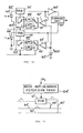
- the difference circuit is provided by an inverting amplifier 38 and a variable gain amplifier. 40.
- the outputs of these amplifiers when summed in a summing circuit 42 is the difference between the electrical signals corresponding to the pair of optical signals from the fibers 22 and 32 which are converted into the electrical signals by the diodes 34 and 36.
- a feedback circuit having a lowpass filter 44 and the variable gain amplifier 40.
- the lowpass filter may have a cutoff at a very low frequency (e.g., a few Hz).
- the gain in the path for amplifying the electrical signal from the diode 36, corresponding to the optical signal from the fiber 22, is varied until the DC or average value of the amplitude thereof is equal to the amplitude of the signal from the other diode• 34, corresponding to the optical signal from the fiber 32.
- the difference in the amplitudes of these electrical signals is obtained from the difference circuit made up of the inverting amplifier 38 and summing circuit 42.
- the difference signal is applied to the gain feedback loop; and with sufficient loop gain, tends to drive the difference to zero.
- the feedback circuit may alternatively be on the opposite side and applied to control the gain of the inverting amplifier which then is a variable gain stage.
- Normalization may be implemented, as shown in FIG. 3, by circuitry having two variable gain amplifiers 45 and 46.
- the average value of the amplitudes of the electrical signals at the outputs of these amplifiers 45 and 46 is normalized to be equal to a reference amplitude equal to the voltage V REF from a reference potential source shown as a battery 48.
- Difference amplifiers 50 and 52 are connected respectively to the outputs of the variable gain amplifiers 46 and 45 and to the source 48.
- the outputs of the differential amplifiers are filtered in lowpass filters 54 and 56 having low cutoff frequencies, again of a few Hz, and applied as error signals to control the gain of the variable gain amplifiers 45 and 46.
- the lowpass filters 44, 54 and 56 have frequencies below the lowest frequency in the frequency spectrum of the mechanical signals applied as the signal input to the deformer of the modulator (viz., to both the gratings 28 and 30 as shown in FIG. 2).
- the feedback circuits including the differential amplifiers 50 and 52 and the filters 54 and 56 not only are the electrical signals corresponding to the optical outputs from the fibers equalized in their average or DC values, but the electrical signal output for a given percent change in light occurring at the FOM is normalized as well. That is, the normalization corrects for such unwanted variations as the intensity of the light source 18 or losses in the transmission fibers 20, 32.
- the difference circuit including the inverting amplifier 38 and the summing circuit 42 thus provides an electrical output which is (a) standardized in output for a given FOM modulation, thus eliminating variations of light intensity in the system other than for which the parameter being sensed is responsible and (b) in which the noise components are substantially eliminated.
- FIGS. 2 and 3 are analog circuits and it may be desirable, particularly when several fiber optic modulators are provided in an array, to process the electrical signals on a digital basis.
- An exemplary digital system is shown in FIG. 4.
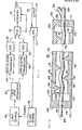
- This system includes a light source 58, such as may contain a light emitting diode or several light emitting diodes each associated with a different fiber optic modulator 60. These modulators may each be of the type described in connection with FIGS. 1 and 2.
- the light source may include a switch, such as a switching transistor circuit, which is repetitively enabled by a train of pulses produced by the clock source 62.
- the clock source 62 also provides an additional train of pulses which may be delayed from the first train of pulses and which identify the time of the return of the light pulses after propagating through the optical waveguide system. These latter clock pulses are synchronous with the clock pulses which operate the light source 58 and control processing of the optical signals.
- the separate outputs from the modulator or modulators 60 are translated into electrical signals by optoelectric transducers 64 and 66. These outputs are sampled by analog to digital converters (ADC) 68 and 70.
- ADC analog to digital converters
- the delayed pulses from the clock source 62 are applied to processing unit (CPU) 72 of a digital processing system 74.
- the processing unit may be a microprocessor of the type generally available,-which provides sampling and address signals to a multiplexer (MUX) 76.
- MUX multiplexer
- each light pulse will produce a pair of outputs in the form of digital signals which are selected by the multiplexer 76 and stored in a memory 78.
- Two digital signals are provided for each light pulse and are read out of the memory on data lines to the CPU 72 where they are normalized and subtracted from each other to provide the differential output.
- This differential output may be a digital signal which is available at the output ports of the CPU.
- the digital signal may be applied to a digital to analog converter and reconverted into analog form.
- the normalization and filtering process as carried on on an analog basis in the systems described in connection with FIGS. 2 and 3 are provided for digitally by manipulation of the digital signals from the memory in the CPU 72 in accordance with a program stored therein or in the memory 78.
- the memory 78, multiplexer 76, and CPU 72 operate both as the normalization circuits and as the difference circuits which was described in connection with FIGS. 1, 2 and 3.
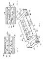
- FIGS. 5 and 6 there is shown a deformer 80 which has an upper section 82 and a lower section 84 of like configuration.
- the lower section is illustrated in FIG. 6.
- Grooves 104 and 106 separate a central portion 98 of the lower section from the ends 110 and 112 thereof.
- the grooves 104 and 106 enable the central portion to flex with respect to the ends 110 and 112.
- the portion 98 of the lower section 84 of the deformer 80 has a row of teeth 90. These teeth are offset from each other longitudinally of the fiber 88 which is deformed.
- the teeth are disposed to periodically deform, by flexure, the fiber 88 as shown in FIG. 5a.
- the upper section 82 also has a central portion 96 with teeth 86 which are offset in a direction longitudinally of the fiber 88 from the teeth 90 in the lower section 84.
- the upper section 82 also has grooves 100 and 102 which separate the central portion 96 from the ends 106 and 108 of the upper section 82 and enable the central portion 96 to flex with respect to the ends 106 and 108 thereof. Except for longitudinal grooves (shown in FIG. 6 as the grooves 103 and 105 in the ends 110 and 112 of the lower section 84) the ends 106, 110 and 108, 112 of the upper and lower sections have their surfaces shown at 114 and 118 in FIG. 6 and by the dark lines at 114 and 118 in FIG. 5a, are dLn contact.
- the inner surface 94 of the central portion 98 of the lower section is opposed to the inner surface 92 of the central portion 96 of the upper section. These surfaces are coincident as shown by the dash line identified by both reference numerals 92 and 94 in FIG. 5a at the maximum inward flexure of the central portions 96 and 98 (which is the maximum flexure and deformation of the fiber 88).
- the surfaces 92 and 94 are apart at less than maximum deflection of the fiber, as when the fiber 88 is not flexed, as shown in FIG.5b and when the bias deformation alone is applied to the fiber 88 as shown in FIG. 5c.
- the teeth 90 are offset from surface 94 of the central portion 98 of the lower section 84 as shown best in FIG.6.
- the teeth 86 are similarly offset from the surface 92 of the central portion 96 of the upper section 82.
- the fiber 88 has a diameter of 10 mils (0.010 inch) and the predetermined deflection which is desired is 2 mils as shown in FIG. 5c.
- the deformer permits only a maximum deflection of 4 mils as shown in FIG. 5a, inasmuch as the opposing surfaces 94 and 92 of the central grating portions 96 and 98 come together into contact as shown in FIG. 5a. This prevents damage to the fiber.
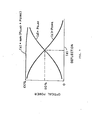
- FIG. 7 illustrates the relationship between the intensity of the light (viz., the optical signal) obtained from the core of the fiber 88 at the output end thereof and from the fiber 126 which taps the light which is coupled into the clad of the fiber 88.
- a predetermined deflection indicated in FIG. 7 as (d) exists where these intensities are balanced and the power of the light coupled to the clad, indicated as curve (b) equals the power of the light remaining in the core as indicated by the curve (c).
- the power is equally portioned, split 50% into the clad and 50% into the core.
- the sum of the clad and core optical power remains close to 100% over the deflection range. This is shown by curve (a) of FIG. 7.
- the optical signals are balanced.
- This balance condition is upset by varying deflection.
- Such varying deflection may be caused by mechancial signals in the form of pressure differentials applied to the outside surfaces 91 and 93 of the deformer, for example, by acoustical energy applied thereto or otherwise by the parameter being sensed.
- the output signals from the difference circuit whether implemented by analog means as shown in FIGS. 2 and 3 or digitally as shown in FIG. 4, corresponds to the parameter which is being transduced, while the noise components remain balanced or nulled in the output.
- the system has many applications as a sensor or transducer for varying types of mechanical signals which may be obtained by acoustic pressure variations or in response to other effects which can be translated into a mechanical signal, (e.g., acceleration).
- Variations and modifications of the hereindescribed system for example to utilize different paths of propagation in the fiber or different optical waveguides or to take advantage of mechanical signals which correspond to various parameters, will undoubtedly suggest themselves to those skilled in the art. Accordingly the foregoing description should be taken as illustrative and not in a limiting sense. So far, the invention may be summarized as follows:
- FIG. 8 there is schematically shown a portion of a cable 10', in which is contained optical hydrophones which contain optical waveguides.
- the optical waveguides are optical fibers.
- These fibers are contained in fiber optic clad/core modulators, three of which 12', 14' and 16'are shown as being representative.
- the fiber optic clad/core modulators (some of which are identified in the drawing by the acronym FOM) may be disposed in the cable 10'so that the sea water carrying the seismic or other acoustic signal to be transduced may be incident on the FOM's 12', 14' and 16'.
- the cable 10', the FOM's 12', 14', and 16'and the components associated with the FOM's provide an optical hydrophone streamer.
- Several hundreds of optical hydrophones in the form of FOM's may be disposed successively along the cable 10'.
- the number of FO M 's and their spacing is determined by the resolution desired of the target or of the earth formation which is to be detected or surveyed.
- the FOM's may be 1 to 3 meters apart along the cable 10'.
- Each of the FOM's has a separate light source, shown as light emitting diodes 18', 20'and 22; associated therewith. It may be desirable to sum the signals from a group of optical hydrophones into a single channel.
- the hydrophones themselves may be separate FOM's which are spaced apart successively along the cable 10'. Either a single light source or separate light sources which are illuminated simultaneously are then used. The signals from the group FOM's will then appear together.
- the streamer with the cable 10' is adapted to be towed through the water, as by a seismic exploration vessel.
- This vessel also serves as the collection point for the signals (viz., the acoustic or seismic pressure) from each observation point. These observation points are the locations of the FOM's.
- a transmission line 24 for electrical pulses is provided which extends along the cable from the collecting point.
- a pulse generator provides the pulses at a rate at which the acoustic or seismic signals are to be sampled by the FOM's at each observation point along the cable.
- a suitable rate may be 1 KHz.
- each section of the transmission line 24" between adjacent optical hydrophones provides a separate pulse delay.
- Exemplary delay circuits 26', 28'and 30' are shown in the sections of the line 24' ahead of the light emitting diodes 18', 20'and 22' which are connected to the outputs of these delay circuits 26', 18'and 30'respectively.
- the circuits may be delay lines and may have amplifiers associated therewith.
- one-shot multivibrators are used which are powered by voltage applied to a power line 32'.
- This voltage is indicated as B+ and may be generated at the collecting point.
- a power supply on the survey vessel may be provided for this purpose.
- An electrical return line 33' which is connected to a reference potential, such as ground, completes the circuits through the LED's 18', 20' and 22'and delay circuits 26', 28'and 30'.
- each delay circuit interposes a 10 microsecond (us) delay to the pulses which are provided at a 1 KHz rate, then the pulses are applied at the 1 KHz rate to each of the LED's but 10'us apart at each successive LED.
- the sampling of each LED is multiplexed in time slots 1000 us apart.
- An observation point (viz., a different FOM) is interrogated every 10 us.
- the maximum sampling rate for a 100 channel streamer is then 100 KHz.
- the hydrophone streamer system with a 1 KHz individual sampling rate (viz., pulses generated at the head end of the line 24'at 1 KHz) can easily have 500 hydrophone channels and can accommodate over 1000 channels
- Sampling theory states that signals sampled at a 1 KHz rate must contain no frequencey components above 500 Hz, or a deleterious effect called aliasing will occur. Consequently, the exemplary sampling frequency of 1 KHz used here could theoretically be used for signals with frequency components as high as 500 Hz.
- an anti-aliasing filter is desirable. Such a filter may have a moderate cut-off slope over, for example, a frequency interval of 2:1. The system then can be effective in sensing signals with frequency components as high as 250 Hz.
- a pair of optical waveguides in the form of optical fibers 34' and 36' are provided as return highways.
- a pair of waveguides in the form of optical fibers are connected from each FOM separately to the return fibers 34'and 36'.
- Each of the FOM's has a pair of output ports connected to output fibers 38' and 40'which carry light, for example, from the core and the clad of an optical fiber waveguide in the modulators.
- These output fibers 38'and 40' are coupled to the return fibers 34' and 36'. It is on these return fibers 34 and 36 that optical output signals corresponding to the parameter being sampled is communicated in time division multiplexed relationship (TDM) back to the collection point.
- TDM time division multiplexed relationship
- the parameter is acoustic (seismic) signals at each observation point at which the FOM's 12', 14'and 16'are located.
- the optical output signals are in the form of optical pulses. Since each FOM is interrogated by an optical pulse generated by its associated LED 18', 10'and 22', when the LED is activated by an electrical pulse transmitted along the transmission line 24', these optical pulses occur in successive time slots.
- the time slots are 10'us in duration in the case where each delay circuits 26', 28' and 30'interposes a 10 ⁇ s delay. Accordingly, the optical signals on the return fibers are time division multiplexed on the return fibers.
- the FOM may be of the type which deforms an optical waveguide to provide a pair of optical outputs.
- FOM 12' is typical and is exemplified in FIG. 9 as having an optical waveguide in the form of an optical fiber 42' having a core 44'and a clad 46'.
- the index of refraction of the clad 46' is lower than the index of refraction of the core. It is to the input end of this optical fiber waveguide 42 that optical pulses are applied from its associated LED 18', when that LED 18 is pulsed by electrical pulses transmitted along the line 24'and which appear at the output of the delay circuit 26'to which the LED 18'is connected.
- the fiber 42' is deformed in response to the signal being transduced which is indicated as M S .
- This signal may be an acoustic or seismic signal which varies the spacing 48 t between plates 50'and 52' having gratings on the opposing surface thereof.
- This grating is represented by teeth 54'and 56'on the inside surface of the plate 50'and a tooth 58'on the inside surface of the plate 52'.
- the optical fiber 42 is deformed by being deflected between the teeth of the grating plates 50'and 52 ⁇ This deformation as explained in the above-referenced patents and articles, particularly the article by Jeun Subscribe and Pocholle, varies the amplitude and of course the power of the light coupled to the clad 46' from the core 44'of the fiber 42'.
- a portion of the light continues to be propagated through the core 44'of the fiber 42'and a portion is coupled to the clad 46'.
- the clad light is tapped by another optical fiber.
- the optical fiber which carries the core light is an output port of the fiber waveguide and is used as an output fiber 38' while the optical fiber which carries the clad light is another output port of the fiber waveguide and is used as the fiber 40'.
- a bias M B to the deformer plates so that the average value of the amplitude, and of course the power, of the light coupled to the output fibers 38' and 40'are balanced on a steady state or average basis.
- balancing of the DC or average value of these optical outputs may be provided by electrical circuitry.
- This electrical circuitry is shown in FIG. 9 as the circuit 60'.
- the circuit 62'as shown in FIG.1o may be used.
- the circuits shown in FIG. 9 and FIG. 10 are analog circuits. If digital processing of the data obtained from the optical hydrophones is desired the circuitry shown in FIG. 17 may alternatively be used.
- noises introduced into the pair of return fibers 34' and 36' be identical. This may be achieved by routing the fibers 34'and 36'together, such that any mechanical deformations which would tend to alter the transmission loss, or in other words modulate the transmitted light intensity (inserting noise),affects each fiber identically.
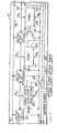
- the circuitry 60' which like the other circuits may be located at the collecting point, makes use of photodetectors 64'and 66'which receive outputs from the return fibers 34'and 36'. These outputs are shown coming from the output fibers 38'and 40'of FOM 12'in FIG. 9. It will be appreciated however that these signals are first communicated via the return fibers 34'and 36'before reaching the photodetectors 64'and 66'.
- One of the photodetectors 64' is connected to an inverting amplifier 68', while the other photodetector 66'is connected to a variable gain amplifier 70'.
- the outputs of these amplifiers are applied to a summing circuit 72', which, due to an inversion in the amplifier 68', provides an electrical output in the form of a pulse corresponding to the difference in amplitude of the optical pulses which are incident upon the photodetector 64'and 66'.
- the output is fed back through a bank of low pass filters 74' (LPF 1 , LPF 2 ... LPF n ) via multiplex stepping switches 77' and 78'. Each filter in the bank is switched in during a successive time slot.
- Switching is controlled by a pulse detector 75'which responds to the pulses from one of the highway fibers, shown in FIG.9 as from the photodetector 66' for example or by other means, such as a delay circuit actuated by the pulses which are applied to the delay circuit 26', so that the switching is in synchonism with the transmission of light pulses through the FOM 12 and the detection thereof by the diodes 64'and 66'.
- the filters 74' each have a cutoff frequency below the minimum frequency of interest. In the case of acoustic signals the cutoff frequency of the filters 74' may be a few Hertz, e.g., 5 Hz.
- the filters provides a control voltage V c to control the gain of the variable gain amplifier 70'.
- the gain of the difference circuit on a DC or average value basis becomes balanced because the gain of the amplifier 70' increases or decreases until the DC or average value of the output from the summing circuit for each individual transducer is reduced.
- the photodetectors 64'and 66' are output connected to variable gain amplifiers 76'and 78'.
- the gain of each of these amplifiers is normalized on a DC or average basis such that the average or DC value of the amplifier outputs equals in amplitude the amplitude of a reference potential V REF which is shown being derived from a battery 80', by way of example.
- the normalization is accomplished by gain control feedback circuits having difference amplifiers 82' and 84'to which the reference potential and the outputs from the variable gain amplifiers 76'and 78'are applied.
- the error signals from the differential amplifiers 82'and 84' are passed through banks of lowpass filters 86'and 88'each of which have their cutoff frequencies below the lowest frequency of interest.
- the filters in the banks 86'and 88' are switched so that a different filter is connected in each successive time slot by multiplex switches 89', 91', 93' and 95'as was explained fcr the bank of filters 74'in FIG. 9.
- the error signals from the lowpass filters thus control the gain of the variable gain amplifiers 76' and 78'so that the DC or average value matches and normalizes the gain to the reference potential V REF .
- the outputs of the variable gain amplifiers are thus balanced on a DC or average value basis.
- the outputs are applied to a difference circuit which is shown schematically as being an inverting amplifier 90'and a summing circuit 92'.
- the summing circuit produces the output corresponding to the difference between the optical signal pulses applied to the photodetectors 64' and 66'from the return fibers 34'and 36'(FIG. 8).
- the electrical outputs from the circuits 64' and 62' as shown in FIGS. 9 and 10 may be multiplexed into different channels corresponding to each of the hydrophone channels by a multiplexer which is operated at a 100 KHz rate in response detected light pulses and provides outputs separated by 10 ⁇ s corresponding to the time slots in which the pulses from the successive transducers (viz., FOM's 12', 14', 16'in FIG. 8) occur.
- the output of the multiplexer may be recorded for later processing which, in the case of seismic signals obtained from a streamer system such as shown in FIG. 8. , will produce seismograms.
- the digital system shown in FIG.17 also uses photodetectors 64'and 66'which respond to the optical pulses from the return fibers 34'and 36'.
- Analog to digital converters (ADC 94'and 96') convert these pulses into digital signals and present them for storage in separate adjacent locations in a memory 98'.
- This memory may be a random access memory (RAM) having locations la, 2a, ... na, for the digital signals (bytes) converted by the ADC 94).
- the memory 98' also is shown as having separate locations lb, 2b, ... nb, for the digital signals converted by the ADC 96'.
- a generator which produces the pulses which are applied to the head end of the transmission line 24' is shown as a clock pulse source 100'.
- Pulses synchronous with these clock pulses are also applied to a processing unit indicated as a CPU 102!
- the CPU may be a microprocessor, for example.
- the CPU is programmed so as to generate address signals which address the memory 98'to the digital signals from the ADC's 94'and 96'via the CPU 102'in the designated locations in the memory 98'. These addresses are applied to the memory by way of an address (ADR) line. Control signals are also applied by way of a control line from the CPU 102' to the memory 98'.
- the data is processed in the CPU 102'under program control so as to enable balancing of the DC or average value of the signals while deriving outputs corresponding to the difference between these signals on a dynamic basis, thus minimizing the noise in the system.
- the CPU 102' provides output data which represents the parameters being sensed (viz., the acoustic or seismic signals) at each observation point.
- the output data may be coded to designate the observation point or hydrophone channel from which it is derived. This data may then be applied to other processing systems for the production of seismograms or other displays of the parameters sensed by the optical transducers.
- sampling systems where the parameter being sensed, such as acoustic pressure variations in the case of the optical hydrophones shown in FIG.17, are sampled at a sampling rate which is the rate at which the light pulses are individually generated at each of the LED 's 18', 20' and 22'.
- this sampling rate may, for example, be 1.0 KHz.
- Sampling theory states that for the parameter to be specified by the samples, the parameter must be a function which contains no frequencies higher than half the sampling rate. A sampling rate at twice the highest frequency of interest in the function being sampled is sometimes called the Nyquist rate. The distortion which results when the parameter being sampled has frequencies above half of the Nyquist rate Is called aliasing.
- a mechanical lowpass anti-aliasing filter 104 is provided in the path of the mechanical signal M S before it is applied to the optical hydrophone.
- This optical hydrophone is shown by way of example as the FOM 12 which was described in connection with FIGS. 1 and 1.
- the FOM includes the optical fiber waveguide 42'.
- the light emitting diode 18' applies light pulses to the input end of the waveguide.
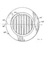
- the waveguide passes through diametral slots 106'and 108'in grating plates 110' and 112',
- the gratings 114'and 116'in these plates 110'and 112' are separated from the tims 118' and 120' by annular grooves 122' and 124'. These grooves define thin walled flexural annular sections 126 and 128.
- the rims 118' and 120' of the plates 110' and 112' are slightly thicker than the thickness of the plates between the apexes of the teeth of the gratings and the outside surfaces of the plates. Accordingly, a predetermined mechanical bias is applied to the fiber 42'which is thereby deflected arid deformed by a predetermined amount so that on a DC or average basis the light retained, for example, in the core of the fiber 42'which appears at the output fiber 38'is equal in amplitude to the light coupled, for example, to the clad which appears at the output of the fiber 40'which taps the clad light.
- annular flexible diaphragm may be disposed within the grooves 122'and 124'to provide separate chambers which are in communication respectively with the ambient sea water environment and with the volume between the gratings 114'and 116'. The latter volume is made much less than the volume of the grooves 122'and 124'.
- gas in the volume between the gratings correspondingly increases in pressure so as to compensate for increasing pressure of the water.
- the hydrophone arrangement having pressure compensation as just described is the subject matter of the above-identified related application, Serial No. 74,27o which is filed concurrently herewith in the name of John V. Bouyoucos.
- That filter is made up of a diaphragm 130' spaced from the outside surface of the grating plate 118'by a cylindrical ring 132'.
- the diaphragm is a flexural member which is subject to displacement in response to pressure variations as caused by acoustic energy such as seismic waves.
- the diaphragm 130' has a stiffness S 1 and a mass M 1 .
- Coupling the diaphragm 130'to the grating plate 118' are two members 132'and 134'.
- the member 134' may be a metal disc having a mass M 2 , which disc is rigid.
- the disc is contained within a hollow cylinder provided with tabs 136' and 138' at opposite ends thereof.
- This hollow cylinder is the member 132 which couples the diaphragm 134' to the grating plate 118 t .
- the tabs 136'and 138' are disposed with their axes along the axis of the grating plate 118 and diaphragm 130'.
- the member 132' may be made of plastic such that it is very flexible but has relatively little mass.
- the stiffness of the member 132' is indicated as S 2 while the mass of the member 134' is indicated as M 2 .
- the grating plate has a mass and stiffness components indicated as M 3 and S 3 .
- the optical fiber 42' presents a stiffness to the system indicated as S 4 .
- the acoustic equivalent circuit of the mechanical anti-aliasing filter 104 is shown in FIG. 16 It is apparent from FIG.16 that the filter is a low-pass filter.
- the various components may be sized so that the cutoff frequency of the filter 104'is well below 500 H z where the interrogation or sampling rate is 1.0 KHz. Aliasing distortion is then eliminated.
- Another anti-aliasing filter 104" is provided on the outside of the grating plate 120'and cooperates with that grating plate.
- the design of the anti-aliasing filter 104" is the same as the design of the above-described anti-aliasing filter 104', and corresponding parts are mixed with corresponding reference numerals but with primes (") at the end thereof.
Applications Claiming Priority (4)
| Application Number | Priority Date | Filing Date | Title |
|---|---|---|---|
| US06/074,268 US4313192A (en) | 1979-09-11 | 1979-09-11 | Optical transducer array system |
| US06/074,270 US4294513A (en) | 1979-09-11 | 1979-09-11 | Optical sensor system |
| US74268 | 1979-09-11 | ||
| US74270 | 2002-02-12 |
Publications (2)
| Publication Number | Publication Date |
|---|---|
| EP0027540A2 true EP0027540A2 (fr) | 1981-04-29 |
| EP0027540A3 EP0027540A3 (fr) | 1981-10-07 |
Family
ID=26755445
Family Applications (1)
| Application Number | Title | Priority Date | Filing Date |
|---|---|---|---|
| EP80105435A Ceased EP0027540A3 (fr) | 1979-09-11 | 1980-09-11 | Sonde optique et arrangement d'un réseau de transducteurs |
Country Status (1)
| Country | Link |
|---|---|
| EP (1) | EP0027540A3 (fr) |
Cited By (18)
| Publication number | Priority date | Publication date | Assignee | Title |
|---|---|---|---|---|
| EP0082615A1 (fr) * | 1981-12-21 | 1983-06-29 | Hughes Aircraft Company | Transducteur opto-mécanique à ondulations de sensibilité réglable |
| EP0082604A1 (fr) * | 1981-12-21 | 1983-06-29 | Hughes Aircraft Company | Hydrophone avec des transducteurs à fibres optiques |
| DE3325945A1 (de) * | 1982-08-03 | 1984-02-09 | Int Standard Electric Corp | Faseroptischer sensor und eine diesen enthaltende sensoreinrichtung |
| GB2125161A (en) * | 1982-07-21 | 1984-02-29 | Gen Electric Co Plc | Optical fibre sensors |
| GB2131171A (en) * | 1982-11-25 | 1984-06-13 | Normalair Garrett | Vorten flowmeter using optical differential pressure sensor |
| EP0175026A1 (fr) * | 1984-09-18 | 1986-03-26 | Western Atlas International, Inc. | Capteur sismique marin |
| WO1987002453A1 (fr) * | 1985-10-21 | 1987-04-23 | Plessey Overseas Limited | Systeme de detection utilisant des capteurs a fibres optiques |
| GB2196735A (en) * | 1986-10-30 | 1988-05-05 | Babcock & Wilcox Co | Strain gauges |
| GB2197066A (en) * | 1986-11-05 | 1988-05-11 | Plessey Co Plc | Bathythermographs or the like |
| US4860586A (en) * | 1988-01-20 | 1989-08-29 | The Babcock & Wilcox Company | Fiberoptic microbend accelerometer |
| AU596376B2 (en) * | 1986-02-03 | 1990-05-03 | International Control Automation Finance Sa | Overload protection for fiber optic microbend sensor |
| US4930862A (en) * | 1988-01-20 | 1990-06-05 | The Babcock & Wilcox Company | Fiberoptic microbend accelerometer |
| US5020379A (en) * | 1986-10-30 | 1991-06-04 | The Babcock & Wilcox Company | Microbend fiber optic strain gauge |
| DE19534260C1 (de) * | 1995-09-15 | 1997-03-27 | Motzko Friedrich Dipl Ing Fh | Seilförmiger faseroptischer Belastungssensor |
| GB2391619A (en) * | 2002-06-04 | 2004-02-11 | Raytheon Co | Differential output optical fiber displacement sensing |
| WO2015036735A1 (fr) * | 2013-09-13 | 2015-03-19 | Silixa Ltd. | Câble acoustique non isotrope |
| WO2016051096A1 (fr) | 2014-10-01 | 2016-04-07 | Phonoptics | Transducteur opto-mécanique pour la détection de vibrations |
| GB2518359B (en) * | 2013-09-13 | 2018-05-23 | Silixa Ltd | Acoustic cables |
Citations (4)
| Publication number | Priority date | Publication date | Assignee | Title |
|---|---|---|---|---|
| US4019051A (en) * | 1975-12-24 | 1977-04-19 | Bell Telephone Laboratories, Incorporated | Directional optical waveguide couplers |
| US4068191A (en) * | 1975-08-22 | 1978-01-10 | Gte Laboratories Incorporated | Acoustooptic modulator for optical fiber waveguides |
| US4142774A (en) * | 1976-06-15 | 1979-03-06 | International Standard Electric Corporation | Flexible optical transducer |
| EP0005798A1 (fr) * | 1978-06-02 | 1979-12-12 | Asea Ab | Appareil de mesure stabilisé, utilisant des fibres optiques |
-
1980
- 1980-09-11 EP EP80105435A patent/EP0027540A3/fr not_active Ceased
Patent Citations (4)
| Publication number | Priority date | Publication date | Assignee | Title |
|---|---|---|---|---|
| US4068191A (en) * | 1975-08-22 | 1978-01-10 | Gte Laboratories Incorporated | Acoustooptic modulator for optical fiber waveguides |
| US4019051A (en) * | 1975-12-24 | 1977-04-19 | Bell Telephone Laboratories, Incorporated | Directional optical waveguide couplers |
| US4142774A (en) * | 1976-06-15 | 1979-03-06 | International Standard Electric Corporation | Flexible optical transducer |
| EP0005798A1 (fr) * | 1978-06-02 | 1979-12-12 | Asea Ab | Appareil de mesure stabilisé, utilisant des fibres optiques |
Non-Patent Citations (4)
| Title |
|---|
| APPLIED PHYSICS LETTERS, Vol. 29, No. 8, 15th October 1976, pages 485-487, New York, U.S.A. L. JEUNHOMME et al.: "Directional coupler for multimode optical fibers" * |
| ELECTRONICS LETT., Vol. 14, No. 11, May 1978, pages 322-324, Hitchin, GB, S.A. KINGSLEY et al.: "Multimode optical-fibre phase modulators and discriminators: I-theory" * |
| FREQUENZ, Vol. 31, No. 12, December 1977, pages 364-368, Berlin, DE, K. ERDEL et al.: "Glasfaser-Bussysteme zur Signalubertragung in Bordnetzen" * |
| OPTICAL FIBRE COMMUNICATION, No. 132, September 1975, pages 165-167, IEE London, GB, D.E.N. DAVIES et al.: "A novel optical fibre telemetry highway" * |
Cited By (25)
| Publication number | Priority date | Publication date | Assignee | Title |
|---|---|---|---|---|
| EP0082604A1 (fr) * | 1981-12-21 | 1983-06-29 | Hughes Aircraft Company | Hydrophone avec des transducteurs à fibres optiques |
| EP0082615A1 (fr) * | 1981-12-21 | 1983-06-29 | Hughes Aircraft Company | Transducteur opto-mécanique à ondulations de sensibilité réglable |
| GB2125161A (en) * | 1982-07-21 | 1984-02-29 | Gen Electric Co Plc | Optical fibre sensors |
| DE3325945A1 (de) * | 1982-08-03 | 1984-02-09 | Int Standard Electric Corp | Faseroptischer sensor und eine diesen enthaltende sensoreinrichtung |
| GB2131171A (en) * | 1982-11-25 | 1984-06-13 | Normalair Garrett | Vorten flowmeter using optical differential pressure sensor |
| EP0175026A1 (fr) * | 1984-09-18 | 1986-03-26 | Western Atlas International, Inc. | Capteur sismique marin |
| US4825424A (en) * | 1985-10-21 | 1989-04-25 | Plessey Overseas Limited | Sensing systems |
| WO1987002453A1 (fr) * | 1985-10-21 | 1987-04-23 | Plessey Overseas Limited | Systeme de detection utilisant des capteurs a fibres optiques |
| GB2184237B (en) * | 1985-10-21 | 1990-01-24 | Plessey Co Plc | Sensing systems |
| AU596376B2 (en) * | 1986-02-03 | 1990-05-03 | International Control Automation Finance Sa | Overload protection for fiber optic microbend sensor |
| GB2196735B (en) * | 1986-10-30 | 1991-01-23 | Babcock & Wilcox Co | Strain gauges |
| GB2196735A (en) * | 1986-10-30 | 1988-05-05 | Babcock & Wilcox Co | Strain gauges |
| US5020379A (en) * | 1986-10-30 | 1991-06-04 | The Babcock & Wilcox Company | Microbend fiber optic strain gauge |
| GB2197066A (en) * | 1986-11-05 | 1988-05-11 | Plessey Co Plc | Bathythermographs or the like |
| GB2197066B (en) * | 1986-11-05 | 1990-11-21 | Plessey Co Plc | Improvements relating to bathythermographs |
| US4930862A (en) * | 1988-01-20 | 1990-06-05 | The Babcock & Wilcox Company | Fiberoptic microbend accelerometer |
| US4860586A (en) * | 1988-01-20 | 1989-08-29 | The Babcock & Wilcox Company | Fiberoptic microbend accelerometer |
| DE19534260C1 (de) * | 1995-09-15 | 1997-03-27 | Motzko Friedrich Dipl Ing Fh | Seilförmiger faseroptischer Belastungssensor |
| DE19534260C2 (de) * | 1995-09-15 | 2002-07-04 | Friedrich Motzko | Seilförmiger faseroptischer Belastungssensor |
| GB2391619A (en) * | 2002-06-04 | 2004-02-11 | Raytheon Co | Differential output optical fiber displacement sensing |
| WO2015036735A1 (fr) * | 2013-09-13 | 2015-03-19 | Silixa Ltd. | Câble acoustique non isotrope |
| US9823114B2 (en) | 2013-09-13 | 2017-11-21 | Silixa Ltd. | Non-isotropic acoustic cable |
| GB2518359B (en) * | 2013-09-13 | 2018-05-23 | Silixa Ltd | Acoustic cables |
| US10345139B2 (en) | 2013-09-13 | 2019-07-09 | Silixa Ltd. | Non-isotropic acoustic cable |
| WO2016051096A1 (fr) | 2014-10-01 | 2016-04-07 | Phonoptics | Transducteur opto-mécanique pour la détection de vibrations |
Also Published As
| Publication number | Publication date |
|---|---|
| EP0027540A3 (fr) | 1981-10-07 |
Similar Documents
| Publication | Publication Date | Title |
|---|---|---|
| US4294513A (en) | Optical sensor system | |
| US4313192A (en) | Optical transducer array system | |
| EP0027540A2 (fr) | Sonde optique et arrangement d'un réseau de transducteurs | |
| US5345522A (en) | Reduced noise fiber optic towed array and method of using same | |
| US4545253A (en) | Fiber optical modulator and data multiplexer | |
| EP0037668B1 (fr) | Transducteur optique | |
| US4649529A (en) | Multi-channel fiber optic sensor system | |
| US5155548A (en) | Passive fiber optic sensor with omnidirectional acoustic sensor and accelerometer | |
| US6346985B1 (en) | Optical method for the transduction of remote arrays of electromechanical sensors | |
| US5497233A (en) | Optical waveguide vibration sensor and method | |
| US4443700A (en) | Optical sensing apparatus and method | |
| US4547869A (en) | Marine seismic sensor | |
| EP1110066B1 (fr) | Systeme optoacoustique recursif de detection sismique | |
| EP0977022B1 (fr) | Dispositif capteur de vibration à guide d'ondes optiques pour la détection à distance | |
| US8755643B2 (en) | Fibre optic sensor package | |
| US6314056B1 (en) | Fiber optic sensor system and method | |
| US7021146B2 (en) | Attitude sensor | |
| US4414471A (en) | Fiber optic acoustic signal transducer using reflector | |
| US4321463A (en) | Low frequency laser fiberoptic detector apparatus for musical instruments and intrusion detection | |
| EP0241530B1 (fr) | Systeme de detection utilisant des capteurs a fibres optiques | |
| US4998225A (en) | Dual beam doppler shift hydrophone | |
| EP1096272B1 (fr) | Dispositif avec des détecteurs acoustiques pour l'application sismique dans le puits utilisant une matrice de palpeurs à fibre optique | |
| WO2005124410A2 (fr) | Capteur optique etendu fonde sur l'intensite | |
| EP0175026B1 (fr) | Capteur sismique marin | |
| Littler et al. | Optical-fiber accelerometer array: Nano-g infrasonic operation in a passive 100 km loop |
Legal Events
| Date | Code | Title | Description |
|---|---|---|---|
| PUAI | Public reference made under article 153(3) epc to a published international application that has entered the european phase |
Free format text: ORIGINAL CODE: 0009012 |
|
| AK | Designated contracting states |
Designated state(s): DE FR GB IT NL SE |
|
| PUAL | Search report despatched |
Free format text: ORIGINAL CODE: 0009013 |
|
| AK | Designated contracting states |
Designated state(s): DE FR GB IT NL SE |
|
| 17P | Request for examination filed |
Effective date: 19811030 |
|
| STAA | Information on the status of an ep patent application or granted ep patent |
Free format text: STATUS: THE APPLICATION HAS BEEN REFUSED |
|
| 18R | Application refused |
Effective date: 19850216 |
|
| RIN1 | Information on inventor provided before grant (corrected) |
Inventor name: BOUYOUCOS, JOHN V. Inventor name: NELSON, DAVID E. |