EP0027223B1 - Single mode optical fibers - Google Patents
Single mode optical fibers Download PDFInfo
- Publication number
- EP0027223B1 EP0027223B1 EP80106026A EP80106026A EP0027223B1 EP 0027223 B1 EP0027223 B1 EP 0027223B1 EP 80106026 A EP80106026 A EP 80106026A EP 80106026 A EP80106026 A EP 80106026A EP 0027223 B1 EP0027223 B1 EP 0027223B1
- Authority
- EP
- European Patent Office
- Prior art keywords
- core
- refractive index
- single mode
- dispersion
- mode optical
- Prior art date
- Legal status (The legal status is an assumption and is not a legal conclusion. Google has not performed a legal analysis and makes no representation as to the accuracy of the status listed.)
- Expired
Links
Images


Classifications
-
- G—PHYSICS
- G02—OPTICS
- G02B—OPTICAL ELEMENTS, SYSTEMS OR APPARATUS
- G02B6/00—Light guides; Structural details of arrangements comprising light guides and other optical elements, e.g. couplings
- G02B6/02—Optical fibres with cladding with or without a coating
- G02B6/02214—Optical fibres with cladding with or without a coating tailored to obtain the desired dispersion, e.g. dispersion shifted, dispersion flattened
- G02B6/02219—Characterised by the wavelength dispersion properties in the silica low loss window around 1550 nm, i.e. S, C, L and U bands from 1460-1675 nm
- G02B6/02228—Dispersion flattened fibres, i.e. having a low dispersion variation over an extended wavelength range
- G02B6/02238—Low dispersion slope fibres
Definitions
- the invention relates to a single mode optical fibre of the step type comprising a core made of glass having a refractive index n 1 and a cladding surrounding the core and made of glass having a refractive index of n 2 , the relative index difference A expressed by and the diameter 2a of the core being so determined that the total dispersion a T formed by the sum of the values of the material dispersion ⁇ M and the waveguide dispersion ⁇ W becomes substantially nil in a predetermined wavelength region.
- n represents the refractive index of the core
- X the wavelength of light
- C the light velocity in vacuum
- the waveguide dispersion is determined by the relationship between the propagation constant ⁇ and the angular frequency of light ⁇ and expressed by the following equation in the case of the single mode optical fibre
- this task is solved in that the values of A and of the core diameter 2a satisfy the relations and are so determined according to the characteristic curve 2a as a function of A plotted in Fig. 4 for a wavelength region included in the hatched area shown in Fig. 4 that the total dispersion ⁇ T is less than ⁇ 1 ps/km/nm and the transmission loss less than 0.5 dB/km. Thereby, it is possible to maintain a tolerable total dispersion ⁇ T over a comparably wide wavelength range.
- both the core and cladding may be made of quartz glass, the core incorporating a dopant increasing its refractive index n, to top the index n 2 of the cladding.
- the dopant may be a member selected from the material group comprising germanium, phosphor, titanium, aluminium, tantalum, zirconium, lead, barium and gallium.
- a single mode optical fiber 10 shown in Fig. 1 comprises a core 11 made of quartz glass or the like, and a cladding 12 made of similar material and surrounding the core. Denoting the refractive index of the core 11 by n 1 , that of the cladding by n 2 and the radius of the core by a, the refractive index distribution of the core as viewed in the radial direction of the optical fiber 10 is shown in Fig. 2. As can be noted from this distribution, the optical fiber of this type has a so-called step type refractive index distribution.
- the refractive index difference between the core 11 and the cladding 12 is expressed by the following equation.
- this refractive index difference ⁇ is selected to lie in a range of from 1% to 3.6% and the diameter 2a of the core 11 is selected to have a suitable value in a range of 4.8 to 3.0 ⁇ m as A varies (i.e., the diameter 2a would decrease as A increases).
- the refractive index difference ⁇ and the core diameter 2a it is possible to obtain an optical fiber having a total dispersion a T of less than ⁇ 1 ps/km/nm and a theoretical value L of the transmission loss closely related to the refractive index difference ⁇ of less than 0.5 dB/km.
- the optical fiber embodying the invention can use a wavelength width of 0.05 to 0.23 pm, depending upon the values of the refractive index difference ⁇ and the core diameter 2a.
- a wavelength width of 0.05 ⁇ m a two wavelength multiplexing becomes possible assuming a spacing of the wavelength multiplexing of 230 A where the wavelength shift of a semiconductor laser caused by temperature variation is 200 A and the spectral width of a light source is from 20 to 30 A.
- the lower limit of the refractive index difference ⁇ is determined by the fact that the bandwidth of the wavelength is 0.05 ⁇ m so that as ⁇ decreases the wavelength width gradually decreases thus making wavelength multiplexing difficult.
- the upper limit of the refractive index difference ⁇ is determined by the fact that as the core diameter becomes smaller than 3 pm, the coupling between adjacent cores as well as the coupling between the core and the light source become imperfect so that losses at these portions increase.
- the coupling construction according to the present invention when the core diameter is 3 pm, it is possible to limit the coupling losses to be less than 10 dB.
- this construction it is possible to improve the photo-coupling efficiency with the light source by 3 to 4 times since the light receiving permissible angle increases due to the increase in the refractive index difference between the core and the cladding.
- the optical fibre when used in a submarine cable the light is perfectly confined within the core due to a high refractive index difference, thus decreasing the increase in the transmission loss caused by hydrostatic pressure in relation to prior art optical fibers.
- Fig. 3 is a graph showing the relationship between the wavelength of the light to be transmitted through the single mode optical fiber of the present invention and the material dispersion ⁇ M , the waveguide dispersion ⁇ W and the total dispersion, i.e., the sum of ⁇ M and ⁇ w .
- the core 11 and the cladding .12 were essentially made of quartz glass.
- a germanium dopant was used for making the refractive index thereof larger than that of the cladding.
- the following table shows the values of the diameter 2a of the core 11 and a wavelength range ⁇ b in which the total dispersion ⁇ T lies in a range of ⁇ 1 ps/km/mn when the refractive index difference A varies between 0.8 and 3.6%.
- Fig. 4 is a graph showing the low dispersion region (a region bounded by ⁇ Tu and ⁇ Td curves) in which ⁇ T is less than ⁇ 1 ps/km/nm for the refractive index difference A, the diameter 2a of the core 11, and a low loss region of less than 0.5 dB/km (a region bounded by curves L u and L d ).
- the advantageous effect of the present invention can be efficiently manifested near this wavelength, as it is known that the transmission loss is minimum near a wavelength of about 1.5 pm.
- the fact that the transmission loss becomes minimum near the wavelength of 1.5 ⁇ m is described in Miya's document entitled "Ultimate low loss single mode fiber at 1.55 pm” and published in Electronics Letters, Vol. 15, No. 4, pages 106-108, Feb. 15, 1979.
- the usable wavelength bandwidth is 1.40-1.45 pm, so that there is the possibility of two wavelength multiplexing.
- the usable wavelength bandwidth is 1.46-1.69 pm so that there is a possibility of 10 wavelength multiplexing.
- the core and cladding were made of quartz glass having a predetermined refractive index
- incorporation of germanium acting as a dopant into the quartz glass increases the refractive index n 1 .
- the dopant or additive may be selected from the group consisting of phosphor, titanium, aluminum, tantalum, zirconium, lead, barium, and gallium.
Landscapes
- Chemical & Material Sciences (AREA)
- Dispersion Chemistry (AREA)
- Physics & Mathematics (AREA)
- General Physics & Mathematics (AREA)
- Optics & Photonics (AREA)
- Optical Communication System (AREA)
- Optical Fibers, Optical Fiber Cores, And Optical Fiber Bundles (AREA)
- Glass Compositions (AREA)
Description
- The invention relates to a single mode optical fibre of the step type comprising a core made of glass having a refractive index n1 and a cladding surrounding the core and made of glass having a refractive index of n2, the relative index difference A expressed by
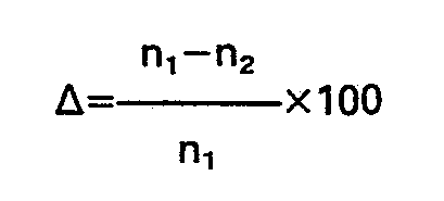
diameter 2a of the core being so determined that the total dispersion aT formed by the sum of the values of the material dispersion σM and the waveguide dispersion σW becomes substantially nil in a predetermined wavelength region. - Various efforts have been made to improve the single mode optical fibre, to meet requirements raised by the development of an optical communication, and in recent years improved single mode optical fibres have been developed which, in addition to ordinary characteristics of light weight, non-inductiveness, and no cross- talking, have a lower loss than a transmission line utilizing such metal conductor as a millimeter wave guide and can transmit data over a wider frequency band. Recently, it was contemplated to use optical fibres for a long distance ultrawide frequency band optical communication at a frequency of 1 GHz and without using any repeating station.
- It has been theoretically classified that it is necessary to reduce the total dispersion to be less than ±1 ps/km/nm and to reduce the transmission loss to be less than 0.5 dB/km in order to realize such a long distance ultra wide band transmission. Considering the transmission characteristics of a present day optical fibre from this standpoint the ultra wide band long distance transmission involves certain problems for the following reasons.
- More particularly, in an optical fibre, light entering into the core transmits therethrough by repeatedly reflecting the interface between the core and the cladding, and the deterioration of the transmission characteristics caused by the dispersion of light can be analysed as follows:
- This is caused by the fact that the propagation constant representing the propagation state of the light varies nonlinearly with respect to the angular frequency of the light and that as the angular frequency increases, higher order modes appear in the light propagating mode so that group velocities vary for different modes.
- This is caused by the fact that the refractive index of glass constituting the optical glass varies non-linearly and thatthe material dispersion σM of a single mode optical fibre is shown by the following equation

- The waveguide dispersion is determined by the relationship between the propagation constant β and the angular frequency of light ω and expressed by the following equation in the case of the single mode optical fibre

- In the case of a multimode optical fibre it is necessary to take into consideration the three dispersions described above. In order to decrease the signal distortion by minimising the dispersions as far as possible it is contemplated to use a single mode optical fibre so that it is not necessary to consider the multimode dispersion but only the material dispersion and the waveguide dispersion. Accordingly, in the case of the single mode optical fibre a sum σM+σW) of the material dispersion OM and the waveguide dispersion σW constitutes the total dispersion σT, and the frequency bandwidth f in which signals can be transmitted without distortion is expressed by the following equation:

- In a typical prior art optical fibre the following values are applied: the diameter of the
core 2a=9.0 pm, the refractive index of the core n,=1.46319, and the difference in the relative refractive indices of the core and cladding
- With such prior art optical fibres, when the wavelength of light e.g. varies in a range of 0.9―1.6 µm, the material dispersion varies in a range of from +66 to -25 ps/km/nm and the difference in the refractive index and the core diameter have values as described, the waveguide dispersion Ow varies in a range of from 4 to 13 ps/km/nm. For this reason the total dispersion aT varies in the positive and negative directions about λ=1.43 pm. Accordingly, when the optical fibre is operated at a wavelength λ=1.43 µm, at which the total dispersion σT becomes zero the distortion of the signal becomes minimum so that transmission over a long distance at a wide bandwidth becomes possible. However, even if the wavelength differs only slightly from 1.43 pm the total dispersion σT increases greatly resulting in that the frequency bandwidth f shown in equation (3) decreases rapidly.
- Accordingly, with such prior art optical fibre, even when the total dispersion σT is made to be equal to ±1 ps/km/nm suitable for long distance transmission the usable wavelength width is merely from 1.41-1.43 µm. Thus, for a long distance wide bandwidth transmission, even when the wavelength is divided or multiplexed for the purpose of improving the transmission efficiency it is impossible to operate the optical fibre in the wavelength range mentioned above. Furthermore, attempts have been made to minimize the total dispersion σT for several chosen values of the relative difference Δ between the refractive indices of the core and the cladding of a fibre and of the core diameter for a particular wavelength range. Such attempts is a single mode optical fibre of the species as set out in the introductory paragraph of this specification have been described in "Electronic Letters, Vol. 15, no. 13 of June 1979, pp. 396-397" and "Applied Optics, Vol. 18, no. 14 of July 1979, pp. 2521-2522". However, these teachings are restricted to a total dispersion of σT=0 for a wavelength λ of approximately 1.5 µm, while σT will differ considerably from zero over a wider wavelength range beyond λ=1.5 pm even if the relative refractive index difference were maintained at Δ=2.4%.
- It is therefore the task of the present invention to provide an improved single mode optical fibre enabling wavelength division multiplex transmission by providing for wider band transmission characteristics by means of optimising a particular characteristic of the optical fibre.
- According to the present invention this task is solved in that the values of A and of the
core diameter 2a satisfy the relations
characteristic curve 2a as a function of A plotted in Fig. 4 for a wavelength region included in the hatched area shown in Fig. 4 that the total dispersion σT is less than ±1 ps/km/nm and the transmission loss less than 0.5 dB/km. Thereby, it is possible to maintain a tolerable total dispersion σT over a comparably wide wavelength range. - Preferably both the core and cladding may be made of quartz glass, the core incorporating a dopant increasing its refractive index n, to top the index n2 of the cladding. This enables an increase in the refractive index difference A. Advantageously, the dopant may be a member selected from the material group comprising germanium, phosphor, titanium, aluminium, tantalum, zirconium, lead, barium and gallium.
- The invention will now be described in greater detail with reference to the accompanying, schematic drawings showing preferred embodiments of the invention.
- In the accompanying drawings:
- Fig. 1 is a perspective view showing the basic construction of a single mode optical fiber embodying the invention;
- Fig. 2 is a graph showing the refractive index distribution in the radial direction of the optical fiber shown in Fig. 1,
- Fig. 3 is a graph showing the relationship between the wavelength and dispersion characteristics σW, σM and σT of the optical fiber shown in Fig. 1 and
- Fig. 4 is a graph showing the relation between the refractive index difference and the wavelength of the light, the core diameter, the total dispersion, and the transmission loss characteristics obtained by simulation.
- A single mode
optical fiber 10 shown in Fig. 1 comprises acore 11 made of quartz glass or the like, and a cladding 12 made of similar material and surrounding the core. Denoting the refractive index of thecore 11 by n1, that of the cladding by n2 and the radius of the core by a, the refractive index distribution of the core as viewed in the radial direction of theoptical fiber 10 is shown in Fig. 2. As can be noted from this distribution, the optical fiber of this type has a so-called step type refractive index distribution. The refractive index difference between thecore 11 and thecladding 12 is expressed by the following equation.
- According to the present invention, this refractive index difference Δ is selected to lie in a range of from 1% to 3.6% and the
diameter 2a of thecore 11 is selected to have a suitable value in a range of 4.8 to 3.0 µm as A varies (i.e., thediameter 2a would decrease as A increases). By using such values of the refractive index difference Δ and thecore diameter 2a, it is possible to obtain an optical fiber having a total dispersion aT of less than ±1 ps/km/nm and a theoretical value L of the transmission loss closely related to the refractive index difference Δ of less than 0.5 dB/km. The optical fiber embodying the invention can use a wavelength width of 0.05 to 0.23 pm, depending upon the values of the refractive index difference Δ and thecore diameter 2a. As a consequence, with a wavelength width of 0.05 µm, a two wavelength multiplexing becomes possible assuming a spacing of the wavelength multiplexing of 230 A where the wavelength shift of a semiconductor laser caused by temperature variation is 200 A and the spectral width of a light source is from 20 to 30 A. - The lower limit of the refractive index difference Δ is determined by the fact that the bandwidth of the wavelength is 0.05 µm so that as Δ decreases the wavelength width gradually decreases thus making wavelength multiplexing difficult. The upper limit of the refractive index difference Δ is determined by the fact that as the core diameter becomes smaller than 3 pm, the coupling between adjacent cores as well as the coupling between the core and the light source become imperfect so that losses at these portions increase. With the coupling construction according to the present invention, when the core diameter is 3 pm, it is possible to limit the coupling losses to be less than 10 dB. Moreover, with this construction, it is possible to improve the photo-coupling efficiency with the light source by 3 to 4 times since the light receiving permissible angle increases due to the increase in the refractive index difference between the core and the cladding.
- Furthermore, when the optical fibre is used in a submarine cable the light is perfectly confined within the core due to a high refractive index difference, thus decreasing the increase in the transmission loss caused by hydrostatic pressure in relation to prior art optical fibers.
- Fig. 3 is a graph showing the relationship between the wavelength of the light to be transmitted through the single mode optical fiber of the present invention and the material dispersion σM, the waveguide dispersion σW and the total dispersion, i.e., the sum of σM and σw. In this case, the
core 11 and the cladding .12 were essentially made of quartz glass. For use as the core a germanium dopant was used for making the refractive index thereof larger than that of the cladding. Thus, the refractive index difference was Δ=2.4%, and the diameter of thecore 11 was 2a=3.46 µm. As can be noted from the characteristics shown in Fig. 3, the total dispersion σT was made to be less than ±1 ps/km/nm for a wavelength range of λ=1.48―2.0 µm. - By using an electronic computer, there has been made a simulation calculation for the purpose of confirming the operation and the advantageous effect of the single mode optical fiber according to the present invention. The following table shows the values of the
diameter 2a of thecore 11 and a wavelength range λb in which the total dispersion σT lies in a range of ±1 ps/km/mn when the refractive index difference A varies between 0.8 and 3.6%.
- Fig. 4 is a graph showing the low dispersion region (a region bounded by σTu and σTd curves) in which σT is less than ±1 ps/km/nm for the refractive index difference A, the
diameter 2a of thecore 11, and a low loss region of less than 0.5 dB/km (a region bounded by curves Lu and Ld). - These characteristic curves show that the value of 2a should be determined in a hatched area shown in Fig. 4 in order to obtain a single mode optical fiber having characteristics presently desired, i.e., a total dispersion of less than ±1 ps/km/nm, and a transmission loss of less than 0.5 dB/km. As described above, the values of A and 2a that determine this area are A=1-3.6%, and 2a=4.78-3.00 µm. For example, to transmit mainly light essentially having a wavelength of about λ=1.5 µm the refractive index difference Δ=2.4―1.5% and the diameter of the
core 11 2a=3.46―4.12 µm are adequate. In a quartz glass optical fiber, the advantageous effect of the present invention can be efficiently manifested near this wavelength, as it is known that the transmission loss is minimum near a wavelength of about 1.5 pm. The fact that the transmission loss becomes minimum near the wavelength of 1.5 µm is described in Miya's document entitled "Ultimate low loss single mode fiber at 1.55 pm" and published in Electronics Letters, Vol. 15, No. 4, pages 106-108, Feb. 15, 1979. - Furthermore, as shown in Fig. 4, where Δ=1.1 % and 2a=4.62 µm, the usable wavelength bandwidth is 1.40-1.45 pm, so that there is the possibility of two wavelength multiplexing. Especially, where A=2.05% and 2a=3.67 pm, the usable wavelength bandwidth is 1.46-1.69 pm so that there is a possibility of 10 wavelength multiplexing.
- Although in the foregoing embodiment the core and cladding were made of quartz glass having a predetermined refractive index, incorporation of germanium acting as a dopant into the quartz glass increases the refractive index n1. Thus, from equation (4) it can be noted that it is possible to increase the refractive index difference Δ. In addition to germanium, the dopant or additive may be selected from the group consisting of phosphor, titanium, aluminum, tantalum, zirconium, lead, barium, and gallium.
Claims (3)


Applications Claiming Priority (2)
| Application Number | Priority Date | Filing Date | Title |
|---|---|---|---|
| JP130449/79 | 1979-10-08 | ||
| JP54130449A JPS583205B2 (en) | 1979-10-08 | 1979-10-08 | Ultra-wideband single mode optical fiber |
Publications (2)
| Publication Number | Publication Date |
|---|---|
| EP0027223A1 EP0027223A1 (en) | 1981-04-22 |
| EP0027223B1 true EP0027223B1 (en) | 1985-10-02 |
Family
ID=15034496
Family Applications (1)
| Application Number | Title | Priority Date | Filing Date |
|---|---|---|---|
| EP80106026A Expired EP0027223B1 (en) | 1979-10-08 | 1980-10-04 | Single mode optical fibers |
Country Status (5)
| Country | Link |
|---|---|
| US (1) | US4525027A (en) |
| EP (1) | EP0027223B1 (en) |
| JP (1) | JPS583205B2 (en) |
| CA (1) | CA1124120A (en) |
| DE (1) | DE3071147D1 (en) |
Families Citing this family (12)
| Publication number | Priority date | Publication date | Assignee | Title |
|---|---|---|---|---|
| FR2496086B1 (en) * | 1980-12-16 | 1985-07-12 | Quartz & Silice | OPTICAL WAVEGUIDE WITH FLUORIC DOPED HEART |
| US4439007A (en) * | 1981-06-09 | 1984-03-27 | Bell Telephone Laboratories, Incorporated | Low dispersion single mode fiber |
| US4412722A (en) * | 1981-10-26 | 1983-11-01 | Western Electric | Single mode fiber with graded index of refraction |
| JPH0188624U (en) * | 1987-11-30 | 1989-06-12 | ||
| US5027079A (en) * | 1990-01-19 | 1991-06-25 | At&T Bell Laboratories | Erbium-doped fiber amplifier |
| US5361319A (en) | 1992-02-04 | 1994-11-01 | Corning Incorporated | Dispersion compensating devices and systems |
| JP3409935B2 (en) * | 1995-01-13 | 2003-05-26 | 富士通株式会社 | Single mode optical fiber, method of manufacturing the same, and optical fiber transmission line |
| US5715346A (en) * | 1995-12-15 | 1998-02-03 | Corning Incorporated | Large effective area single mode optical waveguide |
| FR2790106B1 (en) * | 1999-02-18 | 2001-05-04 | Cit Alcatel | BROADBAND INDEX JUMP FIBER |
| JP2003279780A (en) * | 2002-01-15 | 2003-10-02 | Sumitomo Electric Ind Ltd | Optical fiber, optical fiber tape, optical cable and optical connector with optical fiber |
| JPWO2005012967A1 (en) * | 2003-08-04 | 2007-09-27 | 住友電気工業株式会社 | Optical fiber |
| TW200508678A (en) * | 2003-08-04 | 2005-03-01 | Sumitomo Electric Industries | Optical transmission line constituting method, optical transmission line and optical fiber |
Family Cites Families (6)
| Publication number | Priority date | Publication date | Assignee | Title |
|---|---|---|---|---|
| US3711262A (en) * | 1970-05-11 | 1973-01-16 | Corning Glass Works | Method of producing optical waveguide fibers |
| US3659915A (en) * | 1970-05-11 | 1972-05-02 | Corning Glass Works | Fused silica optical waveguide |
| US3778132A (en) * | 1972-10-06 | 1973-12-11 | Bell Telephone Labor Inc | Optical transmission line |
| US4089586A (en) * | 1976-06-23 | 1978-05-16 | Bell Telephone Laboratories, Incorporated | Single mode optical transmission line |
| JPS5565909A (en) * | 1978-11-13 | 1980-05-17 | Nippon Telegr & Teleph Corp <Ntt> | Optical fiber |
| US4402570A (en) * | 1981-04-13 | 1983-09-06 | The United States Of America As Represented By The Secretary Of The Navy | Triple minimum dispersion wavelengths for a high NA single-mode step-index fiber |
-
1979
- 1979-10-08 JP JP54130449A patent/JPS583205B2/en not_active Expired
-
1980
- 1980-10-01 CA CA361,299A patent/CA1124120A/en not_active Expired
- 1980-10-04 DE DE8080106026T patent/DE3071147D1/en not_active Expired
- 1980-10-04 EP EP80106026A patent/EP0027223B1/en not_active Expired
-
1984
- 1984-09-05 US US06/648,334 patent/US4525027A/en not_active Expired - Lifetime
Non-Patent Citations (2)
| Title |
|---|
| Applied Optics, vol. 18, no. 14, July 1979, pages 2521-2522 * |
| Electronics letters, vol. 15, no. 13, June 1979, pages 396,397. * |
Also Published As
| Publication number | Publication date |
|---|---|
| JPS5652705A (en) | 1981-05-12 |
| US4525027A (en) | 1985-06-25 |
| EP0027223A1 (en) | 1981-04-22 |
| JPS583205B2 (en) | 1983-01-20 |
| DE3071147D1 (en) | 1985-11-07 |
| CA1124120A (en) | 1982-05-25 |
Similar Documents
| Publication | Publication Date | Title |
|---|---|---|
| EP0026937B1 (en) | Single mode optical fibers | |
| US4402570A (en) | Triple minimum dispersion wavelengths for a high NA single-mode step-index fiber | |
| US4889404A (en) | Asymmetrical bidirectional telecommunication system | |
| KR960001319B1 (en) | Optical fiber | |
| US5852701A (en) | Dispersion-shifted fiber | |
| US6263138B1 (en) | Optical fiber for compensating chromatic dispersion of a positive chromatic dispersion optical fiber | |
| KR100642035B1 (en) | Optical fiber and optical transmission system including the same | |
| US4755022A (en) | Zero dispersion single mode optical fiber with center core and side core in the 1.5 μm wavelength region | |
| Tsuchiya et al. | Dispersion-free single-mode fibre in 1.5 μm wavelength region | |
| EP1338102B1 (en) | Optical fiber for to-the-home distribution networks | |
| US6879764B2 (en) | Dispersion shifted fiber having low dispersion slope | |
| KR20010007258A (en) | Multi-mode optical fiber having improved refractive index profile and devices comprising same | |
| EP0307228A2 (en) | Few-mode/single-mode fiber | |
| EP0831345A2 (en) | Optical fiber grating | |
| EP0027223A1 (en) | Single mode optical fibers | |
| CN110741293B (en) | Fiber Optics and Optical Transmission Systems | |
| US6633714B2 (en) | Optical fiber for wavelength division multiplex transmission systems | |
| Kitayama et al. | Design considerations for the structural optimization of a single-mode fiber | |
| EP0021712B1 (en) | Dielectric waveguides and method of propagating polarized electromagnetic waves and communication apparatus and system using such waveguides and method | |
| US6763168B2 (en) | Optical fiber for in-line compensation of chromatic dispersion in an optical fiber with positive chromatic dispersion | |
| US6856736B2 (en) | Lightwaveguide cable and process for carrying an optical signal using dispersion management | |
| US4986629A (en) | Monomode optical fiber with protection against tapping of transmitted information, and a transmission method using said fiber | |
| EP4116749B1 (en) | Optical waveguide device and optical communication system including same | |
| US7209620B2 (en) | Dispersion optimized fiber having higher spot area | |
| JPS583206B2 (en) | Single mode optical fiber with intermediate layer |
Legal Events
| Date | Code | Title | Description |
|---|---|---|---|
| PUAI | Public reference made under article 153(3) epc to a published international application that has entered the european phase |
Free format text: ORIGINAL CODE: 0009012 |
|
| AK | Designated contracting states |
Designated state(s): DE FR GB IT NL |
|
| 17P | Request for examination filed |
Effective date: 19811003 |
|
| R17P | Request for examination filed (corrected) |
Effective date: 19811003 |
|
| ITF | It: translation for a ep patent filed | ||
| GRAA | (expected) grant |
Free format text: ORIGINAL CODE: 0009210 |
|
| AK | Designated contracting states |
Designated state(s): DE FR GB IT NL |
|
| REF | Corresponds to: |
Ref document number: 3071147 Country of ref document: DE Date of ref document: 19851107 |
|
| RAP2 | Party data changed (patent owner data changed or rights of a patent transferred) |
Owner name: NIPPON TELEGRAPH AND TELEPHONE CORPORATION |
|
| ET | Fr: translation filed | ||
| PLBE | No opposition filed within time limit |
Free format text: ORIGINAL CODE: 0009261 |
|
| STAA | Information on the status of an ep patent application or granted ep patent |
Free format text: STATUS: NO OPPOSITION FILED WITHIN TIME LIMIT |
|
| NLT2 | Nl: modifications (of names), taken from the european patent patent bulletin |
Owner name: NIPPON TELEGRAPH AND TELEPHONE CORPORATION TE TOKI |
|
| 26N | No opposition filed | ||
| PGFP | Annual fee paid to national office [announced via postgrant information from national office to epo] |
Ref country code: FR Payment date: 19900907 Year of fee payment: 11 |
|
| PGFP | Annual fee paid to national office [announced via postgrant information from national office to epo] |
Ref country code: GB Payment date: 19900914 Year of fee payment: 11 |
|
| ITTA | It: last paid annual fee | ||
| PGFP | Annual fee paid to national office [announced via postgrant information from national office to epo] |
Ref country code: NL Payment date: 19901031 Year of fee payment: 11 |
|
| PGFP | Annual fee paid to national office [announced via postgrant information from national office to epo] |
Ref country code: DE Payment date: 19901221 Year of fee payment: 11 |
|
| PG25 | Lapsed in a contracting state [announced via postgrant information from national office to epo] |
Ref country code: GB Effective date: 19911004 |
|
| PG25 | Lapsed in a contracting state [announced via postgrant information from national office to epo] |
Ref country code: NL Effective date: 19920501 |
|
| GBPC | Gb: european patent ceased through non-payment of renewal fee | ||
| NLV4 | Nl: lapsed or anulled due to non-payment of the annual fee | ||
| PG25 | Lapsed in a contracting state [announced via postgrant information from national office to epo] |
Ref country code: FR Effective date: 19920630 |
|
| PG25 | Lapsed in a contracting state [announced via postgrant information from national office to epo] |
Ref country code: DE Effective date: 19920701 |
|
| REG | Reference to a national code |
Ref country code: FR Ref legal event code: ST |