EP0026625B1 - Method and apparatus for producing multi-component glass fiber preform - Google Patents
Method and apparatus for producing multi-component glass fiber preform Download PDFInfo
- Publication number
- EP0026625B1 EP0026625B1 EP80303322A EP80303322A EP0026625B1 EP 0026625 B1 EP0026625 B1 EP 0026625B1 EP 80303322 A EP80303322 A EP 80303322A EP 80303322 A EP80303322 A EP 80303322A EP 0026625 B1 EP0026625 B1 EP 0026625B1
- Authority
- EP
- European Patent Office
- Prior art keywords
- raw material
- preform
- glass
- substrate
- glass raw
- Prior art date
- Legal status (The legal status is an assumption and is not a legal conclusion. Google has not performed a legal analysis and makes no representation as to the accuracy of the status listed.)
- Expired
Links
Images

Classifications
-
- C—CHEMISTRY; METALLURGY
- C03—GLASS; MINERAL OR SLAG WOOL
- C03C—CHEMICAL COMPOSITION OF GLASSES, GLAZES OR VITREOUS ENAMELS; SURFACE TREATMENT OF GLASS; SURFACE TREATMENT OF FIBRES OR FILAMENTS MADE FROM GLASS, MINERALS OR SLAGS; JOINING GLASS TO GLASS OR OTHER MATERIALS
- C03C13/00—Fibre or filament compositions
- C03C13/04—Fibre optics, e.g. core and clad fibre compositions
- C03C13/045—Silica-containing oxide glass compositions
- C03C13/046—Multicomponent glass compositions
-
- C—CHEMISTRY; METALLURGY
- C03—GLASS; MINERAL OR SLAG WOOL
- C03B—MANUFACTURE, SHAPING, OR SUPPLEMENTARY PROCESSES
- C03B37/00—Manufacture or treatment of flakes, fibres, or filaments from softened glass, minerals, or slags
- C03B37/01—Manufacture of glass fibres or filaments
- C03B37/012—Manufacture of preforms for drawing fibres or filaments
- C03B37/014—Manufacture of preforms for drawing fibres or filaments made entirely or partially by chemical means, e.g. vapour phase deposition of bulk porous glass either by outside vapour deposition [OVD], or by outside vapour phase oxidation [OVPO] or by vapour axial deposition [VAD]
- C03B37/01413—Reactant delivery systems
-
- C—CHEMISTRY; METALLURGY
- C03—GLASS; MINERAL OR SLAG WOOL
- C03B—MANUFACTURE, SHAPING, OR SUPPLEMENTARY PROCESSES
- C03B37/00—Manufacture or treatment of flakes, fibres, or filaments from softened glass, minerals, or slags
- C03B37/01—Manufacture of glass fibres or filaments
- C03B37/012—Manufacture of preforms for drawing fibres or filaments
- C03B37/014—Manufacture of preforms for drawing fibres or filaments made entirely or partially by chemical means, e.g. vapour phase deposition of bulk porous glass either by outside vapour deposition [OVD], or by outside vapour phase oxidation [OVPO] or by vapour axial deposition [VAD]
- C03B37/01413—Reactant delivery systems
- C03B37/0142—Reactant deposition burners
-
- C—CHEMISTRY; METALLURGY
- C03—GLASS; MINERAL OR SLAG WOOL
- C03B—MANUFACTURE, SHAPING, OR SUPPLEMENTARY PROCESSES
- C03B37/00—Manufacture or treatment of flakes, fibres, or filaments from softened glass, minerals, or slags
- C03B37/01—Manufacture of glass fibres or filaments
- C03B37/012—Manufacture of preforms for drawing fibres or filaments
- C03B37/014—Manufacture of preforms for drawing fibres or filaments made entirely or partially by chemical means, e.g. vapour phase deposition of bulk porous glass either by outside vapour deposition [OVD], or by outside vapour phase oxidation [OVPO] or by vapour axial deposition [VAD]
- C03B37/018—Manufacture of preforms for drawing fibres or filaments made entirely or partially by chemical means, e.g. vapour phase deposition of bulk porous glass either by outside vapour deposition [OVD], or by outside vapour phase oxidation [OVPO] or by vapour axial deposition [VAD] by glass deposition on a glass substrate, e.g. by inside-, modified-, plasma- or plasma modified- chemical vapour deposition [ICVD, MCVD, PCVD, PMCVD], i.e. by thin layer coating on the inside or outside of a glass tube or on a glass rod
- C03B37/01807—Reactant delivery systems, e.g. reactant deposition burners
-
- C—CHEMISTRY; METALLURGY
- C03—GLASS; MINERAL OR SLAG WOOL
- C03B—MANUFACTURE, SHAPING, OR SUPPLEMENTARY PROCESSES
- C03B2201/00—Type of glass produced
- C03B2201/06—Doped silica-based glasses
- C03B2201/30—Doped silica-based glasses doped with metals, e.g. Ga, Sn, Sb, Pb or Bi
-
- C—CHEMISTRY; METALLURGY
- C03—GLASS; MINERAL OR SLAG WOOL
- C03B—MANUFACTURE, SHAPING, OR SUPPLEMENTARY PROCESSES
- C03B2201/00—Type of glass produced
- C03B2201/06—Doped silica-based glasses
- C03B2201/30—Doped silica-based glasses doped with metals, e.g. Ga, Sn, Sb, Pb or Bi
- C03B2201/34—Doped silica-based glasses doped with metals, e.g. Ga, Sn, Sb, Pb or Bi doped with rare earth metals, i.e. with Sc, Y or lanthanides, e.g. for laser-amplifiers
-
- C—CHEMISTRY; METALLURGY
- C03—GLASS; MINERAL OR SLAG WOOL
- C03B—MANUFACTURE, SHAPING, OR SUPPLEMENTARY PROCESSES
- C03B2201/00—Type of glass produced
- C03B2201/06—Doped silica-based glasses
- C03B2201/30—Doped silica-based glasses doped with metals, e.g. Ga, Sn, Sb, Pb or Bi
- C03B2201/50—Doped silica-based glasses doped with metals, e.g. Ga, Sn, Sb, Pb or Bi doped with alkali metals
-
- C—CHEMISTRY; METALLURGY
- C03—GLASS; MINERAL OR SLAG WOOL
- C03B—MANUFACTURE, SHAPING, OR SUPPLEMENTARY PROCESSES
- C03B2201/00—Type of glass produced
- C03B2201/06—Doped silica-based glasses
- C03B2201/30—Doped silica-based glasses doped with metals, e.g. Ga, Sn, Sb, Pb or Bi
- C03B2201/54—Doped silica-based glasses doped with metals, e.g. Ga, Sn, Sb, Pb or Bi doped with beryllium, magnesium or alkaline earth metals
-
- C—CHEMISTRY; METALLURGY
- C03—GLASS; MINERAL OR SLAG WOOL
- C03B—MANUFACTURE, SHAPING, OR SUPPLEMENTARY PROCESSES
- C03B2203/00—Fibre product details, e.g. structure, shape
- C03B2203/10—Internal structure or shape details
- C03B2203/22—Radial profile of refractive index, composition or softening point
-
- C—CHEMISTRY; METALLURGY
- C03—GLASS; MINERAL OR SLAG WOOL
- C03B—MANUFACTURE, SHAPING, OR SUPPLEMENTARY PROCESSES
- C03B2203/00—Fibre product details, e.g. structure, shape
- C03B2203/10—Internal structure or shape details
- C03B2203/22—Radial profile of refractive index, composition or softening point
- C03B2203/26—Parabolic or graded index [GRIN] core profile
-
- C—CHEMISTRY; METALLURGY
- C03—GLASS; MINERAL OR SLAG WOOL
- C03B—MANUFACTURE, SHAPING, OR SUPPLEMENTARY PROCESSES
- C03B2207/00—Glass deposition burners
- C03B2207/04—Multi-nested ports
- C03B2207/06—Concentric circular ports
-
- C—CHEMISTRY; METALLURGY
- C03—GLASS; MINERAL OR SLAG WOOL
- C03B—MANUFACTURE, SHAPING, OR SUPPLEMENTARY PROCESSES
- C03B2207/00—Glass deposition burners
- C03B2207/04—Multi-nested ports
- C03B2207/08—Recessed or protruding ports
-
- C—CHEMISTRY; METALLURGY
- C03—GLASS; MINERAL OR SLAG WOOL
- C03B—MANUFACTURE, SHAPING, OR SUPPLEMENTARY PROCESSES
- C03B2207/00—Glass deposition burners
- C03B2207/20—Specific substances in specified ports, e.g. all gas flows specified
-
- C—CHEMISTRY; METALLURGY
- C03—GLASS; MINERAL OR SLAG WOOL
- C03B—MANUFACTURE, SHAPING, OR SUPPLEMENTARY PROCESSES
- C03B2207/00—Glass deposition burners
- C03B2207/20—Specific substances in specified ports, e.g. all gas flows specified
- C03B2207/26—Multiple ports for glass precursor
- C03B2207/28—Multiple ports for glass precursor for different glass precursors, reactants or modifiers
-
- C—CHEMISTRY; METALLURGY
- C03—GLASS; MINERAL OR SLAG WOOL
- C03B—MANUFACTURE, SHAPING, OR SUPPLEMENTARY PROCESSES
- C03B2207/00—Glass deposition burners
- C03B2207/30—For glass precursor of non-standard type, e.g. solid SiH3F
- C03B2207/32—Non-halide
-
- C—CHEMISTRY; METALLURGY
- C03—GLASS; MINERAL OR SLAG WOOL
- C03B—MANUFACTURE, SHAPING, OR SUPPLEMENTARY PROCESSES
- C03B2207/00—Glass deposition burners
- C03B2207/30—For glass precursor of non-standard type, e.g. solid SiH3F
- C03B2207/34—Liquid, e.g. mist or aerosol
-
- C—CHEMISTRY; METALLURGY
- C03—GLASS; MINERAL OR SLAG WOOL
- C03B—MANUFACTURE, SHAPING, OR SUPPLEMENTARY PROCESSES
- C03B2207/00—Glass deposition burners
- C03B2207/40—Mechanical flame shields
Definitions
- This invention relates to a method and apparatus for making a multi-component glass fiber preform for fabricating optical fibers for use as transmission lines in communication systems.
- multi-component preform denotes a preform composed of a plurality of components.
- optical fibers used as transmission lines of optical communication include silica glass fibers, multi-component glass fibers and ionic crystal fibers. It is required that these optical fibers have low loss, are inexpensive to manufacture and can employ wide band signals. Further, these optical fibers are required to enable easy connection between the fibers and to have a high mechanical strength.
- Conventional multi-component glass fibers comprise silica Si0 2 and a dopant composed of at least one metal salt selected from the group consisting of alkali metal oxide such as Na 2 0, alkaline earth metal oxide such as MgO, oxide of lead such as PbO and oxide of lanthanum such as La203.
- alkali metal oxide such as Na 2
- alkaline earth metal oxide such as MgO
- oxide of lead such as PbO
- oxide of lanthanum such as La203.
- Such multi-component glass fibers can be easily fabricated from a preform since they have a relatively low melting temperature.
- Such multi-component glass fibers have another advantage that they have low loss since Rayleigh scattering involved is kept to a low level.
- Another object is to provide an apparatus for producing such a preform which apparatus is simple in construction.
- a method for producing a multi-component glass fiber preform which comprises the steps of nebulizing an aqueous solution of at least one metal salt, and reacting the atomized solution and a gaseous glass raw material with oxygen gas at a high temperature to produce particulate glass material deposited on a substrate.
- the glass raw material is SiCl 4 , and if desired, one or more of GeCl 4 , POC1 3 and BBr 3 may be added.
- the aqueous solution is prepared using at least one metal salt selected from the group consisting of alkali metal nitrate, alkali metal carbonate, alkali metal sulfate, alkali metal acetate, alkaline earth metal nitrate, alkaline earth metal carbonate, alkaline earth metal sulfate, alkaline earth metal acetate, lead nitrate, lead carbonate, lead sulfate, lead acetate, lanthanium nitrate, lanthanium carbonate, lanthanium sulfate and lanthanium acetate.
- the glass raw material and the nebulized solution are mixed togther and reacted with oxygen gas at a high temperature to produce particulate glass material or soot deposited on the substrate to form a multi- component glass fiber preform.
- the aqueous solution of metal salt or salts is nebulized using a nebulizer utilizing supersonic vibration.
- the substrate may be in the form of a bar.
- the particulate glass material may be deposited on one end or the outer periphery of the substrate bar of circular cross-section.
- the substrate may take the form of a tube, in which instance the particulate glass material is deposited on the inner periphery of the substrate tube.
- the bar is axially rotated and moved, and the tube is axially rotated.
- the preform is drawn axially to form an optical fiber.
- the amount of the dopant, i.e., the metal salt or salts contained in the preform can be increased so that the refractive index of the preform can be controlled to form an optical fiber either of the core clad type or the graded index type.
- the substrate tube may be made of silica.
- the particulate glass material is deposited on the inner periphery of the tube to produce a multi-component glass fiber preform.
- the tube was heated to collapse its hollow portion to provide a solid construction.
- the preform is drawn axially together with the tube to provide a jacketed optical fiber, the tube constituting the jacket for the optical fiber.
- the jacketed optical fiber has an increased mechanical strength.
- an apparatus for producing a multi-component glass fiber preform which apparatus comprises a multi-conduit burner having five concentric conduits, the centrally disposed first conduit and the second and third conduits adjacent thereto being flush with one another at their tip ends, the fourth conduit interposed between the third and outermost conduits extending axially beyond them, in first to fifth conduits serving to feed a gaseous glass raw material, a fuel gas, an nebulized aqueous solution of at least one metal salt, an inert gas and oxygen gas, respectively, the burner having a nozzle adapted to be directed to an axially rotating and moving substrate to deposit particulate glass raw material on the substrate.
- the dopant content of the glass fiber preform can be increased.
- silicon chloride SiC 1 4 gas is used as the gaseous glass raw material.
- One or more of germanium chloride gas GeCl 4 , phosphoryl chloride gas POC1 3 , and boron bromide BBR 3 may be added to SiCI 4 to prepare the glass raw material.
- SiCl 4 , GeC14, POC1 3 and BBr 3 are first purified by precise distillation, and then gasified. The gasification is carried out by slowly heating a container filled with these materials and bubbling a carrier gas through the materials in the container. High purity argon gas, helium gas or oxygen gas can be used as the carrier gas.
- the dopant is at least one metal salt selected from the group consisting of alkali metal nitrate, alkali metal carbonate, alkali metal sulfate, alkali metal acetate, alkaline earth metal nitrate, alkaline earth metal carbonate, alkaline earth metal sulfate, alkaline earth metal acetate, lead nitrate, lead carbonate, lead sulfate: lead acetate, lanthanium nitrate, lanthanium carbonate, lanthanium sulfate and lanthanium acetate.
- alkali metal lithium, sodium potassium and cesium can be used.
- As the alkaline earth metal magnesium, calcium and barium can be used.
- the aqeuous solution of metal salt or salts is subjected to extremely high purification, using a solvent extraction method or an ion exchange resin.
- the purified solution is nebulized by a nebulizer utilizing supersonic vibration.
- an inert gas such as argon and helium gases of high purity is used as the carrier gas.
- Oxygen gas serving to oxidize the glass raw materials and the nebulized solution should preferably have a purity of more than 99.99%.
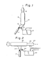
- Fig. 1 shows a preform forming apparatus 10 which comprises a multi-conduit burner 11 having a plurality of concentric conduits.
- a gaseous. glass raw material, H 2 , O 2 and a carrier gas such as argon or helium are fed simultaneously through their respective conduits.
- the hydrogen gas is burnt to form a flame 12.
- the glass raw material is composed of SiCl 4 and one or more of GeCl 4 , BBr 3 and POCI 3 .
- the glass raw material is gasified by the bubbling operation as described above.
- the aqueous solution is nebulized and injected from a nozzle 14 into the flame 12.
- the glass raw material and the nebulized material is subjected by the oxygen gas to chemical reactions such as flame hydrolysis and oxidation to produce a multi-component particulate glass material or soot.
- the particulate material is directed by the flame 12 toward and deposited on the lower end of a substrate bar 1 5.
- the particulate material or soot comprises oxides of the glass raw material such as SiO 2 , GeO 2 , B 2 O 3 , and P 2 O 5 , oxides of the metal salt such as Na 2 O, MgO and PbO, and oxides such as those containing Si-O-Na bond, Si-O-Mg bond and Si-O-Pb bond.
- the substrate bar 15 is supported on a lath (not shown) for axial rotation and upward movement along the axis.
- the multicomponent particulate glass material or soot is desposited on the lower end of the thus rotating and moving bar 15 to form a porous multi-component glass fiber preform 16.
- the glass fiber preform 16 having a desired refractive index profile can be obtained.
- Fig. 2 shows a modified preform forming apparatus 20.
- a gaseous glass raw material, oxygen gas, hydrogen gas and a carrier gas such as argon or helium gas are simultaneously fed through respective conduits of a multi-conduit burner 21, as described above for the burner 11.
- the glass raw material is composed of SiCl 4 , and one or more of GeCl 4 , POCl 3 and BBr 3 .
- An aqueous solution of metal salt or salts, purified according to the procedure described above, is contained in a nebulizer 23.
- Argon gas under pressure is supplied as a carrier gas into the nebulizer 23 through a pipe 24a and the purified solution is nebulized by supersonic vibration and injected from the nozzle 24 into a flame 22 of the burner 21.
- the glass raw material and the nebulized material are oxidized by the oxygen gas to allow their oxides in the form of particular glass material or soot to deposit on the outer periphery of a substrate bar 25 to produce a porous multi-component glass fiber preform 26.
- the substrate bar 25 is supported on a lathe (not shown) for axially rotation and reciprocal movement along the axis during the deposition operation.
- the refractive index of the preform 26 can be changed either in a continous or a stepped manner in the radial direction of the substrate bar 25.
- Fig. 3 shows a multi-conduit burner 31 having five concentric conduits 31 a to 31 e.
- the first to fifth conduits 31 a to 31 e serve to feed the above-mentioned glass raw material, hydrogen gas, the above-mentioned nebulized metal salt solution, argon gas and oxygen gas, respectively.
- the gaseous glass raw material is fed through the centrally disposed first conduit 31 a by a carrier gas such as argon gas.
- the first to third conduits 31 a to 31 are flush with one another at their tip ends.
- the fourth conduit 31 d is about 15 to 20 mm longer than the first to third conduits and also is about 5 mm longer than the fifth conduit 31e.
- a mixture area 32 is defined by the fourth conduit 31 d and the tip ends of the first to third conduits 31 a to 31 c.
- the mixture area 32 serves to sufficiently mix the materials emitted from the first to fourth conduits 31 a to 31 d.
- a flange member 33 is mounted around the outermost or fifth conduit 31 e and extends axially beyond the fourth conduit 31 d. Hydrogen gas is burnt to form a flame 34.
- the glass raw material and the nebulized metal salt solution, emitted respectively from the conduits 31 a and 31 c, are adequately mixed together and directed into the flame 34 so that the particulate glass raw material or soot is produced by oxidization and deposited on the lower end of a substrate bar 35 to produce a porous multi-component glass fiber preform 36, as shown in Fig. 4 which schematically illustrates a further modified preform forming apparatus 30.
- the substrate bar 35 is supported on a lathe (not shown) for axial rotation and movement along the axis during the deposition operation. With this method, the dopant content of the obtained preform can be easily increased to a desired level.
- the substrate bar 35 may be arranged for horizontal reciprocal movement so that the glass fiber preform is formed around the outer periphery of the substrate. Further, as described above, by controlling the feed rate of one or more components of the materials supplied through the multi-conduits burner 31, the refractive index of the preform can be controlled. Also, as described above, by changing the flow rates of the glass raw materials and nebulized materials, the distance between the nozzle of the burner 31 and the lower end of the substrate bar 35, and the angle of the burner 31 with respect to the substrate 35, the glass fiber preform having a desired refractive index profile can be obtained.
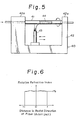
- Fig. 5 shows a further modified preform forming apparatus 40 which employs a process commonly known in the trade as "modified chemical vapor deposition process".
- An elongated hollow substrate 41 in the form of silica tube is used.
- the substrate tube 41 is supported by spaced support portions 42a, 42a of a lathe 42 for axial rotation.
- a burner 43 using H 2 and O2 is mounted on the lathe 42 beneath the substrate tube 41 for reciprocal movement therealong to heat the rotating tube 41.
- the tube 41 has a smooth bore or inner peripheral wall which is cleaned.
- the above-mentioned gaseous glass raw material and nebulized solution, oxygen gas and the carrier gas are introduced into the bore of the rotating tube 41.
- the glass raw material and nebulized material are heated by the moving burner 43 so that the particulate glass material or soot is produced through chemical reactions such as flame hydrolysis and oxidization and is deposited on the inner peripheral surface of the silica tube 41 to form a porous multi-component preform 44.
- the refractive index of the preform 44 can be changed either in a continuous or a stepped manner.
- the preform is heated to a temperature above a melting points for vitrification to provide a transparent glass preform.
- the vitrified preform is then drawn to form an optical fiber. More specifically, where a core preform and a cladding preform are formed on separte substrate bars, the two preforms are introduced respectively into concentrically disposed inner and outer chambers of a crucible, e.g., a platinum crucible and are melted. The preforms thus treated are drawn to provide a multi-component optical glass fiber having a core portion and a cladding portion.
- a core preform is formed on the lower end of the substrate bar, and thereafter a cladding preform is formed on the core preform to provide an integral preform.
- This integral preform is heated for vitrification to obtain a transparent preform.
- This transparent preform is drawn to provide a multi-component optical glass fiber.
- the preform is vitrified to obtain a transparent glass preform in the manner described above. Then, the substrate bar is removed from the preform, and this hollow preform is heated to collapse the hollow portion to provide a solid construction. In the case of the preform of which refractive index is varied in the radial direction, the preform is simply drawn to form a multi-component optical glass fiber. In the case of the preform of which refractive index is constant in the radial direction, the preform is formed into a rod of a predetermined diameter. Then, a cladding is applied over the preform, and the preform with the cladding is drawn to provide a multicomponent glass fiber.
- the substrate tube, in which the preform is formed is heated to collapse the hollow portion to form a solid structure.
- the preform with the silica tube is drawn axially from one end to form a multi-component optical glass fiber.
- the d'rawn tube 41 serves as a jacket for the optical fiber and increases the mechanical strength of the fiber.
- aqueous solution of 30% by weight NaN0 3 of extremely high purity was prepared, using an ion exchange resin.
- the purified aqueous solution was charged into a nebulizer 13 of a preform forming apparatus 10 shown in Fig. 1, the nebulizer 13 utilizing supersonic vibration, SiCl 4 , GeCl 4 , BBr 3 and POC1 3 serving as gaseous glass raw materials were fed through a first conduit of a multi-conduit burner 11 at the flow rates of 200 cc per minute, 100 cc per minute, 50 cc per minute and 20 cc per minute, respectively, the multi-conduit burner 11 having a plurality of concentrically disposed conduits.
- Hydrogen gas serving as a fuel gas and oxygen gas were also fed separately through a second and a third conduit at the flow rates of 4000 cc per minute and 6000 cc per minute, respectively, the hydrogen gas being burnt to form a flame 12.
- the purified aqueous solution was subjected to supersonic vibration of 80 kHz by the nebulizer 13, having a power of 50W, to be nebulized at the nozzle 14 of the nebulizer 13 and injected into the flame 12 so that the glass raw materials and the nebulized material were oxidized by the oxygen gas to allow their oxides in soot form to deposit on the lower end of an axially rotating and moving substrate bar 15 to produce a porous multi- component glass fiber preform 16 for a core.
- the aqueous solution to be nebulized was fed at a rate of 50 cc per minute.
- a porous multi-component glass fiber preform for a cladding was also prepared using SiCI 4 (flow rate: 200 cc per minute), GeCI 4 (50 cc per minute), BBr 3 (50 cc per minute) and POCl 3 (20 cc per minute) serving as glass raw materials, hydrogen gas (4000 cc per minute), oxygen gas (6000 cc per minute) and an aqueous solution of 30% by weight NaN0 3 nebulized at the rate of 40 cc per minute.
- the thus obtained core preform and cladding preform were heated in a furnace, respectively, for vitrification to obtain two transparent glass preforms.
- the vitrified core preform and cladding preform were introduced respectively into concentrically-disposed inner and outer chambers of a platinum crucible. Then, the two preforms were drawn at the rate of 20 cm per minute at a temperature of 800° to fabricate a multi-component optical glass fiber having a core portion and a cladding portion.
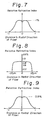
- the thus obtained optical fiber exhibited a refractive index profile of the step type as indicated by a graph in Fig. 6.
- a multi-component optical glass fiber was obtained according to the procedure of Example 1, except that an aqueous solution of 32% by weight KNO 3 was used instead of the aqueous solution of NaNO a .
- the thus obtained optical fiber like the optical fiber of Example 1, exhibited a refractive index profile of the step type.
- aqueous solution of 30% by weight MgS0 4 of extremely high purity and an aqueous solution of 30% by weight C S S0 4 of extremely high purity were prepared, using an ion exchange resin.
- the two solutions were mixed in equal amounts, and the resultant mixture solution was charged into a nebulizer 23 of a preform forming apparatus 20 showing in Fig. 2.
- Argon gas under pressure serving as a carrier gas was fed through a conduit 24a to nebulize the solution.
- SiCI 4 and POC1 3 serving as gaseous glass raw materials, H 2 and O2 were fed through respective conduits of a multi-conduit burner 21, as described above for the burner 11, at the flow rates of 100 cc per minute, 50 cc per minute, 2200 cc per minute and 3000 cc per minute.
- the hydrogen gas was burnt to form a flame 22.
- the mixture solution was nebulized at the nozzle 24 of the nebulizer 23 at a rate of 0.3g per minute and injected into the flame 22 so that the glass raw materials and the nebulized material were oxidized by the oxygen gas to allow their oxides in soot form to deposit on the outer peripheral surface of a substrate bar 25, rotating about its axis and reciprocally moving along its axis, to produce a porous multi-component glass fiber preform 26.
- the substrate bar 25 was rotated at a rate of 20 r.p.m. and reciprocally moved at a speed of 300 mm per minute.
- the amount of SiCI 4 fed to the burner 21 was increased by 5 cc per minute in the range of between 100 cc per minute and 200 cc per minute every one reciprocal movement of the substrate 10.
- the thus obtained preform 26 was heated for vitrification in a carbon resistor furnace at a temperature of about 1400°C to obtain a transparent glass preform. Then, the substrate bar 25 is removed from the preform, and the resulting hollow preform was heated to collapse the hollow portion to provide a solid construction. The solid preform was drawn from one end thereof to produce a multi-component optical glass fiber of the graded index type. The refractive index profile of the optical fiber was matched substantially to a parabolic curve as plotted in Fig. 7.
- a multi-conduit burner 31 (Fig. 3) having five concentric conduits 31 a to 31 e was employed.
- SiCl 4 , POCl 3 and Ar were fed through the first or central conduit 31 a at flow rates of 120 cc per minute, 10 cc per minute and 50 cc per minute, respectively, SiCl 4 and POCl 3 constituting glass raw materials.
- H 2 was supplied through the second conduit 31b at a flow rate of 31 per minute PB(NO 3 ) 2 and H 2 O mixed in the weight ratio of 3:10 was fed through the third conduit 31 at a rate of 0.28g per minute, the mixture being in nebulized form.
- Ar was fed through the fourth conduit 31 d at a rate of 41 per minute.
- O 2 was fed through the fifth conduit 31 at a rate of 31 per minute.
- H 2 was burnt to form a flame 34 and the glass raw material and the nebulized mixture were oxidized by the oxygen gas to allow their particulate oxides to deposit on the lower end of a substrate bar 35 to produce a multi- component glass fiber preform 36 (Fig. 4).
- the substrate bar 35 was rotated axially at a rate of 20 r.p.m. and moved upwardly at a speed of 40 mm per hour.
- the thus produced preform was passed through a carbon resistor furnace, maintained at a temperature of about 1,300°C, for vitrification to obtain a transparent glass preform.
- the transparent preform was drawn by a lathe to have a predetermined diameter or cross-section, and a tube of silica was fitted over the thus drawn material. Then, the drawn material with the silica tube was heated at a temperature of about 2,000°C to obtain a multi-component optical glass fiber.
- the refractive index profile of the optical fiber is shown in Fig. 8.
- a multi-component optical glass fiber of the graded index type was prepared, using a preform forming apparatus 40 shown in Fig. 5.
- An aqueous solution of 30% by weight Pb(NO 3 ) 2 of high purity and an aqueous solution of 20% by weight Ba(CH 3 COO) 2 of high purity were prepared, using either a solvent extraction method or an ion exchange resin.
- the two solutions were mixed in equal amounts, and the resultant mixture solution was nebulized by an nebulizer (not shown) using argon as a carrier gas and was introduced into a tube 41 of silica.
- the amount of argon gas supplied was increased by 8 cc per minute in the range of between 0 cc per minute and 400 cc per minute every one reciprocal movement of a burner 43 along the tube 41, so that the amount of the nebulized mixture supplied was controlled to the range of between Og per minute and 0.5g per minute.
- SiCI 4 and POCI 3 serving as glass raw materials, and O 2 were fed into the tube 41 at flow rates of 150 cc per minute, 30 cc per minute and 200 cc per minute, respectively.
- the tube 41 was supported by a lathe 42 and axially rotated at a rate of 20 r.p.m.
- the tube 41 had an inner diameter of 18 mm, and the length of the tube between opposed support portions 42a, 42a was 1 m.
- the tube 41 was heated by the burner 43 using H 2 and O2 which burner was reciprocally moved along the tube 41 at a speed of 30 cm per minute.
- the glass raw material and the nebulized material in the tube 41 were oxidized by the oxygen gas in the tube to allow their particulate oxides to deposit on the inner periphery of the tube 41 to produce a multi-component glass fiber preform 44.
- the burner 43 reciprocally moved along the tube 41 fifty times, the introduction of the materials into the tube 51 was stopped.
- the tube 41 was heated to 1,900°C to collapse the hollow portion of the tube to provide a solid structure.
- the solid preform with the tube was drawn at 2,100°C at a speed of 30 m per minute to produce a jacketed multi-component optical glass fiber.
- the tube 41 is simultaneously drawn to form jacket for the optical fiber.
- the refractive index profile of the optical fiber was matched substantially to a parabolic curve as plotted in Fig. 9.
Landscapes
- Chemical & Material Sciences (AREA)
- Engineering & Computer Science (AREA)
- Geochemistry & Mineralogy (AREA)
- Life Sciences & Earth Sciences (AREA)
- General Chemical & Material Sciences (AREA)
- Chemical Kinetics & Catalysis (AREA)
- Materials Engineering (AREA)
- Organic Chemistry (AREA)
- General Life Sciences & Earth Sciences (AREA)
- Manufacturing & Machinery (AREA)
- Physics & Mathematics (AREA)
- Optics & Photonics (AREA)
- Manufacture, Treatment Of Glass Fibers (AREA)
Description
- This invention relates to a method and apparatus for making a multi-component glass fiber preform for fabricating optical fibers for use as transmission lines in communication systems. The term "multi-component preform" denotes a preform composed of a plurality of components.
- Conventional optical fibers used as transmission lines of optical communication include silica glass fibers, multi-component glass fibers and ionic crystal fibers. It is required that these optical fibers have low loss, are inexpensive to manufacture and can employ wide band signals. Further, these optical fibers are required to enable easy connection between the fibers and to have a high mechanical strength.
- Conventional multi-component glass fibers comprise silica Si02 and a dopant composed of at least one metal salt selected from the group consisting of alkali metal oxide such as
Na 20, alkaline earth metal oxide such as MgO, oxide of lead such as PbO and oxide of lanthanum such as La203. Such multi-component glass fibers can be easily fabricated from a preform since they have a relatively low melting temperature. Such multi-component glass fibers have another advantage that they have low loss since Rayleigh scattering involved is kept to a low level. - Various methods have been proposed for making a multi-component glass fiber preform. With these methods, starting materials are first subjected to extremely high purification and then are mixed together. Thereafter, the so mixed materials are melted by heat. Thus, these methods have been found not simple. Particularly, where powder materials such as sodium salt, potassium salt, barium salt and lead salt are employed, it is not so easy to mix the starting materials homogeneously. In addition, it is necessary to melt the mixed starting materials, for example, in a crucible for a long period of time. As a result, impurities tend to be introduced into the starting materials during this melting operation. The resultant multi-component glass fiber preform has often failed to provide for optical fibers with low loss.
- It is therefore an object of this invention to provide a method for producing a multi-component glass fiber preform which method is quite simple and ensures that a multi- component optical fiber with low loss is provided.
- Another object is to provide an apparatus for producing such a preform which apparatus is simple in construction.
- According to a first aspect of the invention, there is provided a method for producing a multi-component glass fiber preform which comprises the steps of nebulizing an aqueous solution of at least one metal salt, and reacting the atomized solution and a gaseous glass raw material with oxygen gas at a high temperature to produce particulate glass material deposited on a substrate.
- The glass raw material is SiCl4, and if desired, one or more of GeCl4, POC13 and BBr3 may be added. The aqueous solution is prepared using at least one metal salt selected from the group consisting of alkali metal nitrate, alkali metal carbonate, alkali metal sulfate, alkali metal acetate, alkaline earth metal nitrate, alkaline earth metal carbonate, alkaline earth metal sulfate, alkaline earth metal acetate, lead nitrate, lead carbonate, lead sulfate, lead acetate, lanthanium nitrate, lanthanium carbonate, lanthanium sulfate and lanthanium acetate. The glass raw material and the nebulized solution are mixed togther and reacted with oxygen gas at a high temperature to produce particulate glass material or soot deposited on the substrate to form a multi- component glass fiber preform. The aqueous solution of metal salt or salts is nebulized using a nebulizer utilizing supersonic vibration. The substrate may be in the form of a bar. In this case, the particulate glass material may be deposited on one end or the outer periphery of the substrate bar of circular cross-section. The substrate may take the form of a tube, in which instance the particulate glass material is deposited on the inner periphery of the substrate tube. During the deposition operation, the bar is axially rotated and moved, and the tube is axially rotated. The preform is drawn axially to form an optical fiber.
- The amount of the dopant, i.e., the metal salt or salts contained in the preform can be increased so that the refractive index of the preform can be controlled to form an optical fiber either of the core clad type or the graded index type.
- The substrate tube may be made of silica. The particulate glass material is deposited on the inner periphery of the tube to produce a multi-component glass fiber preform. The tube was heated to collapse its hollow portion to provide a solid construction. The preform is drawn axially together with the tube to provide a jacketed optical fiber, the tube constituting the jacket for the optical fiber. The jacketed optical fiber has an increased mechanical strength.
- According to a second aspect of the invention, there is provided an apparatus for producing a multi-component glass fiber preform which apparatus comprises a multi-conduit burner having five concentric conduits, the centrally disposed first conduit and the second and third conduits adjacent thereto being flush with one another at their tip ends, the fourth conduit interposed between the third and outermost conduits extending axially beyond them, in first to fifth conduits serving to feed a gaseous glass raw material, a fuel gas, an nebulized aqueous solution of at least one metal salt, an inert gas and oxygen gas, respectively, the burner having a nozzle adapted to be directed to an axially rotating and moving substrate to deposit particulate glass raw material on the substrate. With this appartaus, the dopant content of the glass fiber preform can be increased.
-
- Fig. 1 is a schematic view showing a preform forming apparatus of this invention;
- Fig. 2 is a view similar to Fig. 1 but showing a modified apparatus;
- Fig. 3 is a schematic view of a multi-conduit burner;
- Fig. 4 is a view similar to Fig. 1 but showing another modified apparatus;
- Fig. 5 is a view similar to Fig. 1 but showing a further modified apparatus; and
- Figs. 6 to 9 are graphs showing the refractive index profile in the direction of diameter of optical fiber preforms provided in accordance with the present invention.
- As the gaseous glass raw material,
silicon chloride SiC 14 gas is used. One or more of germanium chloride gas GeCl4, phosphoryl chloride gas POC13, and boron bromide BBR3 may be added to SiCI4 to prepare the glass raw material. SiCl4, GeC14, POC13 and BBr3 are first purified by precise distillation, and then gasified. The gasification is carried out by slowly heating a container filled with these materials and bubbling a carrier gas through the materials in the container. High purity argon gas, helium gas or oxygen gas can be used as the carrier gas. - The dopant is at least one metal salt selected from the group consisting of alkali metal nitrate, alkali metal carbonate, alkali metal sulfate, alkali metal acetate, alkaline earth metal nitrate, alkaline earth metal carbonate, alkaline earth metal sulfate, alkaline earth metal acetate, lead nitrate, lead carbonate, lead sulfate: lead acetate, lanthanium nitrate, lanthanium carbonate, lanthanium sulfate and lanthanium acetate. As the alkali metal, lithium, sodium potassium and cesium can be used. As the alkaline earth metal, magnesium, calcium and barium can be used. The aqeuous solution of metal salt or salts is subjected to extremely high purification, using a solvent extraction method or an ion exchange resin. The purified solution is nebulized by a nebulizer utilizing supersonic vibration. Preferably, an inert gas such as argon and helium gases of high purity is used as the carrier gas.
- Oxygen gas serving to oxidize the glass raw materials and the nebulized solution should preferably have a purity of more than 99.99%.
- The invention will now be described with reference to the drawings.
- Fig. 1 shows a
preform forming apparatus 10 which comprises a multi-conduit burner 11 having a plurality of concentric conduits. A gaseous. glass raw material, H2, O2 and a carrier gas such as argon or helium are fed simultaneously through their respective conduits. The hydrogen gas is burnt to form aflame 12. As described above, the glass raw material is composed of SiCl4 and one or more of GeCl4, BBr3 and POCI3. The glass raw material is gasified by the bubbling operation as described above. An aqueous solution of metal salt or salts, which serve as a dopant as described above, in highly purified and charged into anebulizer 13 utilizing supersonic vibration. The aqueous solution is nebulized and injected from anozzle 14 into theflame 12. In theflame 12, the glass raw material and the nebulized material is subjected by the oxygen gas to chemical reactions such as flame hydrolysis and oxidation to produce a multi-component particulate glass material or soot. The particulate material is directed by theflame 12 toward and deposited on the lower end of asubstrate bar 1 5. The particulate material or soot comprises oxides of the glass raw material such as SiO2, GeO2, B2O3, and P2O5, oxides of the metal salt such as Na2O, MgO and PbO, and oxides such as those containing Si-O-Na bond, Si-O-Mg bond and Si-O-Pb bond. Thesubstrate bar 15 is supported on a lath (not shown) for axial rotation and upward movement along the axis. The multicomponent particulate glass material or soot is desposited on the lower end of the thus rotating and movingbar 15 to form a porous multi-componentglass fiber preform 16. During the deposition operation, by changing the flow rates of the glass raw material and the nebulized material, the distance between the nozzle of the burner 11 and the lower end of thesubstrate bar 15, and the angle of the burner 11 with respect to thesubstrate 15, theglass fiber preform 16 having a desired refractive index profile can be obtained. - Fig. 2 shows a modified
preform forming apparatus 20. A gaseous glass raw material, oxygen gas, hydrogen gas and a carrier gas such as argon or helium gas are simultaneously fed through respective conduits of amulti-conduit burner 21, as described above for the burner 11. As described above, the glass raw material is composed of SiCl4, and one or more of GeCl4, POCl3 and BBr3. An aqueous solution of metal salt or salts, purified according to the procedure described above, is contained in anebulizer 23. Argon gas under pressure is supplied as a carrier gas into thenebulizer 23 through a pipe 24a and the purified solution is nebulized by supersonic vibration and injected from thenozzle 24 into aflame 22 of theburner 21. The glass raw material and the nebulized material are oxidized by the oxygen gas to allow their oxides in the form of particular glass material or soot to deposit on the outer periphery of asubstrate bar 25 to produce a porous multi-componentglass fiber preform 26. Thesubstrate bar 25 is supported on a lathe (not shown) for axially rotation and reciprocal movement along the axis during the deposition operation. By controlling the feed rate of one or more components of the glass raw material and nebulized metal salt solution during the reciprocal movement of thesubstrate bar 25, the refractive index of thepreform 26 can be changed either in a continous or a stepped manner in the radial direction of thesubstrate bar 25. - Fig. 3 shows a
multi-conduit burner 31 having fiveconcentric conduits 31 a to 31 e. The first tofifth conduits 31 a to 31 e serve to feed the above-mentioned glass raw material, hydrogen gas, the above-mentioned nebulized metal salt solution, argon gas and oxygen gas, respectively. The gaseous glass raw material is fed through the centrally disposedfirst conduit 31 a by a carrier gas such as argon gas. The first tothird conduits 31 a to 31 are flush with one another at their tip ends. The fourth conduit 31 d is about 15 to 20 mm longer than the first to third conduits and also is about 5 mm longer than the fifth conduit 31e. With this construction, amixture area 32 is defined by the fourth conduit 31 d and the tip ends of the first tothird conduits 31 a to 31 c. Themixture area 32 serves to sufficiently mix the materials emitted from the first tofourth conduits 31 a to 31 d. Aflange member 33 is mounted around the outermost or fifth conduit 31 e and extends axially beyond the fourth conduit 31 d. Hydrogen gas is burnt to form aflame 34. - The glass raw material and the nebulized metal salt solution, emitted respectively from the
conduits flame 34 so that the particulate glass raw material or soot is produced by oxidization and deposited on the lower end of asubstrate bar 35 to produce a porous multi-componentglass fiber preform 36, as shown in Fig. 4 which schematically illustrates a further modifiedpreform forming apparatus 30. Thesubstrate bar 35 is supported on a lathe (not shown) for axial rotation and movement along the axis during the deposition operation. With this method, the dopant content of the obtained preform can be easily increased to a desired level. Thesubstrate bar 35 may be arranged for horizontal reciprocal movement so that the glass fiber preform is formed around the outer periphery of the substrate. Further, as described above, by controlling the feed rate of one or more components of the materials supplied through themulti-conduits burner 31, the refractive index of the preform can be controlled. Also, as described above, by changing the flow rates of the glass raw materials and nebulized materials, the distance between the nozzle of theburner 31 and the lower end of thesubstrate bar 35, and the angle of theburner 31 with respect to thesubstrate 35, the glass fiber preform having a desired refractive index profile can be obtained. - Fig. 5 shows a further modified
preform forming apparatus 40 which employs a process commonly known in the trade as "modified chemical vapor deposition process". An elongatedhollow substrate 41 in the form of silica tube is used. Thesubstrate tube 41 is supported by spaced support portions 42a, 42a of alathe 42 for axial rotation. Aburner 43 using H2 and O2 is mounted on thelathe 42 beneath thesubstrate tube 41 for reciprocal movement therealong to heat the rotatingtube 41. Thetube 41 has a smooth bore or inner peripheral wall which is cleaned. The above-mentioned gaseous glass raw material and nebulized solution, oxygen gas and the carrier gas are introduced into the bore of therotating tube 41. The glass raw material and nebulized material are heated by the movingburner 43 so that the particulate glass material or soot is produced through chemical reactions such as flame hydrolysis and oxidization and is deposited on the inner peripheral surface of thesilica tube 41 to form a porousmulti-component preform 44. As described above, by controlling the feed rate of one or more components of the glass raw material and nebulized metal salt solution during the reciprocal movement of theburner 43, the refractive index of thepreform 44 can be changed either in a continuous or a stepped manner. - For fabricating a multi-component glass fiber from the multi-component glass fiber preforms produced according to the procedures shown in Figs. 1 and 4, the preform is heated to a temperature above a melting points for vitrification to provide a transparent glass preform. The vitrified preform is then drawn to form an optical fiber. More specifically, where a core preform and a cladding preform are formed on separte substrate bars, the two preforms are introduced respectively into concentrically disposed inner and outer chambers of a crucible, e.g., a platinum crucible and are melted. The preforms thus treated are drawn to provide a multi-component optical glass fiber having a core portion and a cladding portion. Alternatively, a core preform is formed on the lower end of the substrate bar, and thereafter a cladding preform is formed on the core preform to provide an integral preform. This integral preform is heated for vitrification to obtain a transparent preform. This transparent preform is drawn to provide a multi-component optical glass fiber.
- For fabricating a glass fiber from the preform prepared according to the procedure shown in Fig. 2, the preform is vitrified to obtain a transparent glass preform in the manner described above. Then, the substrate bar is removed from the preform, and this hollow preform is heated to collapse the hollow portion to provide a solid construction. In the case of the preform of which refractive index is varied in the radial direction, the preform is simply drawn to form a multi-component optical glass fiber. In the case of the preform of which refractive index is constant in the radial direction, the preform is formed into a rod of a predetermined diameter. Then, a cladding is applied over the preform, and the preform with the cladding is drawn to provide a multicomponent glass fiber.
- For fabricating a glass fiber from the preform prepared according to the procedure shown in Fig. 4, the substrate tube, in which the preform is formed, is heated to collapse the hollow portion to form a solid structure. The preform with the silica tube is drawn axially from one end to form a multi-component optical glass fiber. The
d'rawn tube 41 serves as a jacket for the optical fiber and increases the mechanical strength of the fiber. - The invention will now be illustrated by the following examples:
- An aqueous solution of 30% by weight NaN03 of extremely high purity was prepared, using an ion exchange resin. The purified aqueous solution was charged into a
nebulizer 13 of apreform forming apparatus 10 shown in Fig. 1, thenebulizer 13 utilizing supersonic vibration, SiCl4, GeCl4, BBr3 and POC13 serving as gaseous glass raw materials were fed through a first conduit of a multi-conduit burner 11 at the flow rates of 200 cc per minute, 100 cc per minute, 50 cc per minute and 20 cc per minute, respectively, the multi-conduit burner 11 having a plurality of concentrically disposed conduits. Hydrogen gas serving as a fuel gas and oxygen gas were also fed separately through a second and a third conduit at the flow rates of 4000 cc per minute and 6000 cc per minute, respectively, the hydrogen gas being burnt to form aflame 12. The purified aqueous solution was subjected to supersonic vibration of 80 kHz by thenebulizer 13, having a power of 50W, to be nebulized at thenozzle 14 of thenebulizer 13 and injected into theflame 12 so that the glass raw materials and the nebulized material were oxidized by the oxygen gas to allow their oxides in soot form to deposit on the lower end of an axially rotating and movingsubstrate bar 15 to produce a porous multi- componentglass fiber preform 16 for a core. The aqueous solution to be nebulized was fed at a rate of 50 cc per minute. - Then, according to the procedure described above, a porous multi-component glass fiber preform for a cladding was also prepared using SiCI4 (flow rate: 200 cc per minute), GeCI4 (50 cc per minute), BBr3 (50 cc per minute) and POCl3 (20 cc per minute) serving as glass raw materials, hydrogen gas (4000 cc per minute), oxygen gas (6000 cc per minute) and an aqueous solution of 30% by weight NaN03 nebulized at the rate of 40 cc per minute.
- The thus obtained core preform and cladding preform were heated in a furnace, respectively, for vitrification to obtain two transparent glass preforms. The vitrified core preform and cladding preform were introduced respectively into concentrically-disposed inner and outer chambers of a platinum crucible. Then, the two preforms were drawn at the rate of 20 cm per minute at a temperature of 800° to fabricate a multi-component optical glass fiber having a core portion and a cladding portion. The thus obtained optical fiber exhibited a refractive index profile of the step type as indicated by a graph in Fig. 6.
- A multi-component optical glass fiber was obtained according to the procedure of Example 1, except that an aqueous solution of 32% by weight KNO3 was used instead of the aqueous solution of NaNOa. The thus obtained optical fiber, like the optical fiber of Example 1, exhibited a refractive index profile of the step type.
- An aqueous solution of 30% by weight MgS04 of extremely high purity and an aqueous solution of 30% by weight CSS04 of extremely high purity were prepared, using an ion exchange resin. The two solutions were mixed in equal amounts, and the resultant mixture solution was charged into a
nebulizer 23 of apreform forming apparatus 20 showing in Fig. 2. Argon gas under pressure serving as a carrier gas was fed through a conduit 24a to nebulize the solution. - SiCI4 and POC13 serving as gaseous glass raw materials, H2 and O2 were fed through respective conduits of a
multi-conduit burner 21, as described above for the burner 11, at the flow rates of 100 cc per minute, 50 cc per minute, 2200 cc per minute and 3000 cc per minute. The hydrogen gas was burnt to form aflame 22. The mixture solution was nebulized at thenozzle 24 of thenebulizer 23 at a rate of 0.3g per minute and injected into theflame 22 so that the glass raw materials and the nebulized material were oxidized by the oxygen gas to allow their oxides in soot form to deposit on the outer peripheral surface of asubstrate bar 25, rotating about its axis and reciprocally moving along its axis, to produce a porous multi-componentglass fiber preform 26. Thesubstrate bar 25 was rotated at a rate of 20 r.p.m. and reciprocally moved at a speed of 300 mm per minute. During the deposition operation, in order to continuously change the refractive index of the preform in its radial direction to obtain an optical fiber of the graded index type, the amount of SiCI4 fed to theburner 21 was increased by 5 cc per minute in the range of between 100 cc per minute and 200 cc per minute every one reciprocal movement of thesubstrate 10. - The thus obtained
preform 26 was heated for vitrification in a carbon resistor furnace at a temperature of about 1400°C to obtain a transparent glass preform. Then, thesubstrate bar 25 is removed from the preform, and the resulting hollow preform was heated to collapse the hollow portion to provide a solid construction. The solid preform was drawn from one end thereof to produce a multi-component optical glass fiber of the graded index type. The refractive index profile of the optical fiber was matched substantially to a parabolic curve as plotted in Fig. 7. - A multi-conduit burner 31 (Fig. 3) having five
concentric conduits 31 a to 31 e was employed. SiCl4, POCl3 and Ar were fed through the first orcentral conduit 31 a at flow rates of 120 cc per minute, 10 cc per minute and 50 cc per minute, respectively, SiCl4 and POCl3 constituting glass raw materials. H2 was supplied through thesecond conduit 31b at a flow rate of 31 per minute PB(NO3)2 and H2O mixed in the weight ratio of 3:10 was fed through thethird conduit 31 at a rate of 0.28g per minute, the mixture being in nebulized form. Ar was fed through the fourth conduit 31 d at a rate of 41 per minute. O2 was fed through thefifth conduit 31 at a rate of 31 per minute. H2 was burnt to form aflame 34 and the glass raw material and the nebulized mixture were oxidized by the oxygen gas to allow their particulate oxides to deposit on the lower end of asubstrate bar 35 to produce a multi- component glass fiber preform 36 (Fig. 4). Thesubstrate bar 35 was rotated axially at a rate of 20 r.p.m. and moved upwardly at a speed of 40 mm per hour. The thus produced preform was passed through a carbon resistor furnace, maintained at a temperature of about 1,300°C, for vitrification to obtain a transparent glass preform. The transparent preform was drawn by a lathe to have a predetermined diameter or cross-section, and a tube of silica was fitted over the thus drawn material. Then, the drawn material with the silica tube was heated at a temperature of about 2,000°C to obtain a multi-component optical glass fiber. The refractive index profile of the optical fiber is shown in Fig. 8. - A multi-component optical glass fiber of the graded index type was prepared, using a
preform forming apparatus 40 shown in Fig. 5. An aqueous solution of 30% by weight Pb(NO3)2 of high purity and an aqueous solution of 20% by weight Ba(CH3COO)2 of high purity were prepared, using either a solvent extraction method or an ion exchange resin. The two solutions were mixed in equal amounts, and the resultant mixture solution was nebulized by an nebulizer (not shown) using argon as a carrier gas and was introduced into atube 41 of silica. The amount of argon gas supplied was increased by 8 cc per minute in the range of between 0 cc per minute and 400 cc per minute every one reciprocal movement of aburner 43 along thetube 41, so that the amount of the nebulized mixture supplied was controlled to the range of between Og per minute and 0.5g per minute. - Simultaneously with the supply of the nebulized mixture into the
tube 41, SiCI4 and POCI3, serving as glass raw materials, and O2 were fed into thetube 41 at flow rates of 150 cc per minute, 30 cc per minute and 200 cc per minute, respectively. Thetube 41 was supported by alathe 42 and axially rotated at a rate of 20 r.p.m. Thetube 41 had an inner diameter of 18 mm, and the length of the tube between opposed support portions 42a, 42a was 1 m. Thetube 41 was heated by theburner 43 using H2 and O2 which burner was reciprocally moved along thetube 41 at a speed of 30 cm per minute. The glass raw material and the nebulized material in thetube 41 were oxidized by the oxygen gas in the tube to allow their particulate oxides to deposit on the inner periphery of thetube 41 to produce a multi-componentglass fiber preform 44. After theburner 43 reciprocally moved along thetube 41 fifty times, the introduction of the materials into the tube 51 was stopped. Then, thetube 41 was heated to 1,900°C to collapse the hollow portion of the tube to provide a solid structure. The solid preform with the tube was drawn at 2,100°C at a speed of 30 m per minute to produce a jacketed multi-component optical glass fiber. Thus, thetube 41 is simultaneously drawn to form jacket for the optical fiber. The refractive index profile of the optical fiber was matched substantially to a parabolic curve as plotted in Fig. 9.
Claims (11)
Applications Claiming Priority (6)
| Application Number | Priority Date | Filing Date | Title |
|---|---|---|---|
| JP12367779A JPS5913453B2 (en) | 1979-09-26 | 1979-09-26 | Method for manufacturing multicomponent glass fiber matrix |
| JP123677/79 | 1979-09-26 | ||
| JP9129280A JPS5914412B2 (en) | 1980-07-04 | 1980-07-04 | Method for manufacturing multicomponent glass fiber |
| JP91292/80 | 1980-07-04 | ||
| JP91930/80 | 1980-07-05 | ||
| JP9193080A JPS5911538B2 (en) | 1980-07-05 | 1980-07-05 | Burner for manufacturing multi-component glass fiber base material |
Publications (3)
| Publication Number | Publication Date |
|---|---|
| EP0026625A2 EP0026625A2 (en) | 1981-04-08 |
| EP0026625A3 EP0026625A3 (en) | 1981-10-07 |
| EP0026625B1 true EP0026625B1 (en) | 1984-03-14 |
Family
ID=27306705
Family Applications (1)
| Application Number | Title | Priority Date | Filing Date |
|---|---|---|---|
| EP80303322A Expired EP0026625B1 (en) | 1979-09-26 | 1980-09-23 | Method and apparatus for producing multi-component glass fiber preform |
Country Status (4)
| Country | Link |
|---|---|
| US (2) | US4336049A (en) |
| EP (1) | EP0026625B1 (en) |
| CA (1) | CA1166527A (en) |
| DE (1) | DE3066999D1 (en) |
Cited By (2)
| Publication number | Priority date | Publication date | Assignee | Title |
|---|---|---|---|---|
| US5979185A (en) * | 1997-07-16 | 1999-11-09 | Corning Incorporated | Method and apparatus for forming silica by combustion of liquid reactants using a heater |
| US6312656B1 (en) | 1995-12-19 | 2001-11-06 | Corning Incorporated | Method for forming silica by combustion of liquid reactants using oxygen |
Families Citing this family (40)
| Publication number | Priority date | Publication date | Assignee | Title |
|---|---|---|---|---|
| US4428760A (en) | 1982-03-25 | 1984-01-31 | International Telephone And Telegraph Corporation | Oxyhydrogen flame torch for optical fiber drawing |
| US4474593A (en) * | 1982-04-26 | 1984-10-02 | At&T Technologies Inc. | Method of fabricating a lightguide fiber |
| DE3326043A1 (en) * | 1983-07-20 | 1985-02-07 | Licentia Gmbh | METHOD FOR PRODUCING A AEROSOL FLOW AND THE USE THEREOF |
| CA1284921C (en) * | 1984-02-27 | 1991-06-18 | Hiroyuki Suda | Method, apparatus and burner for fabricating an optical fiber preform |
| DE3417438A1 (en) * | 1984-05-11 | 1985-11-14 | Licentia Patent-Verwaltungs-Gmbh, 6000 Frankfurt | METHOD AND DEVICE FOR PRODUCING AN AEROSOL FLOW |
| DE3434598A1 (en) * | 1984-09-20 | 1986-03-27 | Siemens AG, 1000 Berlin und 8000 München | METHOD FOR PRODUCING PREFORM FROM GLASS FOR OPTICAL FIBERS |
| US4666247A (en) * | 1985-02-08 | 1987-05-19 | American Telephone And Telegraph Company, At&T Bell Laboratories | Multiconstituent optical fiber |
| US4645524A (en) * | 1985-04-22 | 1987-02-24 | Corning Glass Works | Method for making sodium-containing glass |
| FR2621909B1 (en) * | 1987-10-16 | 1990-01-19 | Comp Generale Electricite | |
| US5151117A (en) * | 1991-06-14 | 1992-09-29 | Corning Incorporated | Solution doping of porous preforms |
| DE69633066D1 (en) | 1995-12-19 | 2004-09-09 | Corning Inc | METHOD AND DEVICE FOR PRODUCING A QUARTZ GLASS BY COMBUSTION OF LIQUID REAGENTS |
| US6672106B1 (en) * | 1998-08-07 | 2004-01-06 | Corning Incorporated | Method and apparatus for forming soot for the manufacture of glass |
| FI116469B (en) * | 1998-10-05 | 2005-11-30 | Liekki Oy | Flame spraying method and apparatus for manufacturing a multi-component glass |
| US6705127B1 (en) | 1998-10-30 | 2004-03-16 | Corning Incorporated | Methods of manufacturing soot for optical fiber preforms and preforms made by the methods |
| AU1316700A (en) * | 1998-10-30 | 2000-05-22 | Corning Incorporated | Methods of manufacturing soot for optical fiber preforms and preforms made by the methods |
| JP2001019464A (en) * | 1999-07-05 | 2001-01-23 | Sumitomo Electric Ind Ltd | Optical fiber drawing apparatus and drawing method |
| US6374642B1 (en) | 2000-03-15 | 2002-04-23 | Corning Incorporated | Method and apparatus for combustion-enhanced vaporization |
| US6363746B1 (en) | 2000-03-15 | 2002-04-02 | Corning Incorporated | Method and apparatus for making multi-component glass soot |
| US20040216494A1 (en) * | 2000-09-19 | 2004-11-04 | Shinichi Kurotani | Burner for combustion or flame hydrolysis, and combustion furnace and process |
| US7441416B2 (en) * | 2000-12-19 | 2008-10-28 | Prysmian Cavi E Sistemi Energia S.R.L. | Method for manufacturing optical fibre preforms |
| US7003984B2 (en) * | 2001-04-30 | 2006-02-28 | Verrillon, Inc. | Hybrid manufacturing process for optical fibers |
| US6910352B2 (en) * | 2002-04-24 | 2005-06-28 | Corning Incorporated | Deposition of high fluorine content silica soot |
| FI115134B (en) * | 2002-06-28 | 2005-03-15 | Liekki Oy | A method for producing doped glass material |
| US20040057692A1 (en) * | 2002-08-28 | 2004-03-25 | Ball Laura J. | Low loss optical fiber and method for making same |
| US7521097B2 (en) * | 2003-06-06 | 2009-04-21 | Nanogram Corporation | Reactive deposition for electrochemical cell production |
| FI116619B (en) * | 2004-07-02 | 2006-01-13 | Liekki Oy | Method and apparatus for producing optical material and optical waveguide |
| US20060130530A1 (en) * | 2004-12-21 | 2006-06-22 | Anderson James G | Method of doping silica glass with an alkali metal, and optical fiber precursor formed therefrom |
| EP1952186A4 (en) * | 2005-11-23 | 2010-08-04 | Corning Inc | Low attenuation non-zero dispersion shifted optical fiber |
| US8069690B2 (en) * | 2005-12-16 | 2011-12-06 | Ofs Fitel, Llc | Apparatus and method for fabricating glass bodies using an aerosol delivery system |
| US7805039B2 (en) * | 2007-05-04 | 2010-09-28 | Weatherford/Lamb, Inc. | Single mode optical fiber with improved bend performance |
| JP5148367B2 (en) | 2007-05-29 | 2013-02-20 | 信越化学工業株式会社 | Manufacturing method of optical fiber preform using high frequency induction thermal plasma torch |
| JP5023016B2 (en) * | 2007-08-10 | 2012-09-12 | 信越化学工業株式会社 | Optical fiber manufacturing apparatus and drawing furnace sealing method |
| WO2009034413A1 (en) * | 2007-09-14 | 2009-03-19 | Draka Comteq B.V. | Optical fiber and method for manufacturing |
| JP5229957B2 (en) * | 2008-02-27 | 2013-07-03 | 信越化学工業株式会社 | Burner for manufacturing glass base material for optical fiber |
| WO2013118389A1 (en) * | 2012-02-09 | 2013-08-15 | 住友電気工業株式会社 | Optical fiber preform manufacturing method, optical fiber preform, and optical fiber |
| DE102012016086A1 (en) * | 2012-08-14 | 2014-02-20 | Thyssenkrupp Uhde Gmbh | Apparatus and method for injecting oxygen into a pressure-charged fluidized bed gasification |
| EP2952485A4 (en) * | 2013-01-29 | 2016-08-31 | Furukawa Electric Co Ltd | Process for producing glass base and optical fiber |
| WO2014119559A1 (en) * | 2013-02-04 | 2014-08-07 | 住友電気工業株式会社 | Optical-fiber preform and method for manufacturing optical-fiber preform |
| US11577982B2 (en) | 2015-10-07 | 2023-02-14 | Corning Incorporated | Method to prevent cracks in optical fiber preforms |
| US9919956B2 (en) * | 2015-10-07 | 2018-03-20 | Corning Incorporated | Method of assembling optical fiber preforms |
Family Cites Families (8)
| Publication number | Priority date | Publication date | Assignee | Title |
|---|---|---|---|---|
| BE756578A (en) * | 1969-09-25 | 1971-03-01 | Voest Ag | METHOD AND DEVICE FOR FOLDING A LANCE INTO HORIZONTAL POSITION |
| US3883336A (en) * | 1974-01-11 | 1975-05-13 | Corning Glass Works | Method of producing glass in a flame |
| US4217027A (en) * | 1974-02-22 | 1980-08-12 | Bell Telephone Laboratories, Incorporated | Optical fiber fabrication and resulting product |
| JPS5927728B2 (en) * | 1977-08-11 | 1984-07-07 | 日本電信電話株式会社 | Manufacturing method of sooty glass rod |
| JPS54134127A (en) * | 1978-04-04 | 1979-10-18 | Nippon Telegr & Teleph Corp <Ntt> | Production of anhydrous basic material for light transmitting fiber |
| JPS54134129A (en) * | 1978-04-04 | 1979-10-18 | Nippon Telegr & Teleph Corp <Ntt> | Manufacture of basic material for light transmitting fiber |
| JPS54160414A (en) * | 1978-06-08 | 1979-12-19 | Nippon Telegraph & Telephone | Production of optical communication fiber material |
| US4230744A (en) * | 1979-02-21 | 1980-10-28 | Corning Glass Works | System for delivering materials to deposition site on optical waveguide blank |
-
1980
- 1980-09-18 CA CA000360496A patent/CA1166527A/en not_active Expired
- 1980-09-22 US US06/189,856 patent/US4336049A/en not_active Expired - Lifetime
- 1980-09-23 EP EP80303322A patent/EP0026625B1/en not_active Expired
- 1980-09-23 DE DE8080303322T patent/DE3066999D1/en not_active Expired
-
1982
- 1982-02-26 US US06/352,568 patent/US4388098A/en not_active Expired - Lifetime
Cited By (2)
| Publication number | Priority date | Publication date | Assignee | Title |
|---|---|---|---|---|
| US6312656B1 (en) | 1995-12-19 | 2001-11-06 | Corning Incorporated | Method for forming silica by combustion of liquid reactants using oxygen |
| US5979185A (en) * | 1997-07-16 | 1999-11-09 | Corning Incorporated | Method and apparatus for forming silica by combustion of liquid reactants using a heater |
Also Published As
| Publication number | Publication date |
|---|---|
| DE3066999D1 (en) | 1984-04-19 |
| US4336049A (en) | 1982-06-22 |
| EP0026625A3 (en) | 1981-10-07 |
| US4388098A (en) | 1983-06-14 |
| CA1166527A (en) | 1984-05-01 |
| EP0026625A2 (en) | 1981-04-08 |
Similar Documents
| Publication | Publication Date | Title |
|---|---|---|
| US4336049A (en) | Method for producing multi-component glass fiber preform | |
| US4135901A (en) | Method of manufacturing glass for optical waveguide | |
| EP0018704B1 (en) | Method of substantially continuously forming an optical waveguide preform and an optical waveguide | |
| CA1104825A (en) | Method and apparatus for manufacturing a glass optical transmission fiber preform | |
| US4378987A (en) | Low temperature method for making optical fibers | |
| US4414012A (en) | Fabrication methods of doped silica glass and optical fiber preform by using the doped silica glass | |
| US4217027A (en) | Optical fiber fabrication and resulting product | |
| EP0185106B1 (en) | Method of producing a rod containing fluorine | |
| GB1500530A (en) | Process for producing optical fibre preforms | |
| US4388094A (en) | Method and apparatus for producing tubular glass article | |
| SU1194266A3 (en) | Method of producing semifinished product for drawing optical fibre | |
| US4642129A (en) | Method for manufacturing preforms of glass for optical fibers | |
| US4932990A (en) | Methods of making optical fiber and products produced thereby | |
| US4915716A (en) | Fabrication of lightguide soot preforms | |
| US4231774A (en) | Method of fabricating large optical preforms | |
| Geisler et al. | Optical Fibres: EPO Applied Technology Series | |
| JPS6048456B2 (en) | Method for manufacturing base material for optical fiber | |
| JPH0525818B2 (en) | ||
| EP0301797B1 (en) | Methods of making optical fiber and products produced thereby | |
| JPH0557216B2 (en) | ||
| EP0023209B1 (en) | Improved optical fiber fabrication process | |
| Schultz | Vapor phase materials and processes for glass optical waveguides | |
| JPS591220B2 (en) | Manufacturing method of optical fiber base material | |
| JPS581051B2 (en) | Manufacturing method for optical transmission materials | |
| JPH0535691B2 (en) |
Legal Events
| Date | Code | Title | Description |
|---|---|---|---|
| PUAI | Public reference made under article 153(3) epc to a published international application that has entered the european phase |
Free format text: ORIGINAL CODE: 0009012 |
|
| AK | Designated contracting states |
Designated state(s): DE FR GB NL |
|
| PUAL | Search report despatched |
Free format text: ORIGINAL CODE: 0009013 |
|
| AK | Designated contracting states |
Designated state(s): DE FR GB NL |
|
| 17P | Request for examination filed |
Effective date: 19810819 |
|
| GRAA | (expected) grant |
Free format text: ORIGINAL CODE: 0009210 |
|
| AK | Designated contracting states |
Designated state(s): DE FR GB NL |
|
| REF | Corresponds to: |
Ref document number: 3066999 Country of ref document: DE Date of ref document: 19840419 |
|
| ET | Fr: translation filed | ||
| PLBE | No opposition filed within time limit |
Free format text: ORIGINAL CODE: 0009261 |
|
| STAA | Information on the status of an ep patent application or granted ep patent |
Free format text: STATUS: NO OPPOSITION FILED WITHIN TIME LIMIT |
|
| 26N | No opposition filed | ||
| REG | Reference to a national code |
Ref country code: GB Ref legal event code: 732 |
|
| REG | Reference to a national code |
Ref country code: FR Ref legal event code: TP |
|
| NLS | Nl: assignments of ep-patents |
Owner name: NIPPON TELEGRAPH AND TELEPHONE CORPORATION EN THE |
|
| PGFP | Annual fee paid to national office [announced via postgrant information from national office to epo] |
Ref country code: FR Payment date: 19990909 Year of fee payment: 20 |
|
| PGFP | Annual fee paid to national office [announced via postgrant information from national office to epo] |
Ref country code: GB Payment date: 19990922 Year of fee payment: 20 |
|
| PGFP | Annual fee paid to national office [announced via postgrant information from national office to epo] |
Ref country code: DE Payment date: 19990927 Year of fee payment: 20 |
|
| PGFP | Annual fee paid to national office [announced via postgrant information from national office to epo] |
Ref country code: NL Payment date: 19990930 Year of fee payment: 20 |
|
| PG25 | Lapsed in a contracting state [announced via postgrant information from national office to epo] |
Ref country code: GB Free format text: LAPSE BECAUSE OF EXPIRATION OF PROTECTION Effective date: 20000922 |
|
| PG25 | Lapsed in a contracting state [announced via postgrant information from national office to epo] |
Ref country code: NL Free format text: LAPSE BECAUSE OF EXPIRATION OF PROTECTION Effective date: 20000923 |
|
| REG | Reference to a national code |
Ref country code: GB Ref legal event code: PE20 Effective date: 20000922 |
|
| NLV7 | Nl: ceased due to reaching the maximum lifetime of a patent |
Effective date: 20000923 |