EP0026564A1 - Safety belt stop - Google Patents
Safety belt stop Download PDFInfo
- Publication number
- EP0026564A1 EP0026564A1 EP80302622A EP80302622A EP0026564A1 EP 0026564 A1 EP0026564 A1 EP 0026564A1 EP 80302622 A EP80302622 A EP 80302622A EP 80302622 A EP80302622 A EP 80302622A EP 0026564 A1 EP0026564 A1 EP 0026564A1
- Authority
- EP
- European Patent Office
- Prior art keywords
- stop
- belt
- slide member
- roller
- run
- Prior art date
- Legal status (The legal status is an assumption and is not a legal conclusion. Google has not performed a legal analysis and makes no representation as to the accuracy of the status listed.)
- Granted
Links
Images

Classifications
-
- A—HUMAN NECESSITIES
- A44—HABERDASHERY; JEWELLERY
- A44B—BUTTONS, PINS, BUCKLES, SLIDE FASTENERS, OR THE LIKE
- A44B11/00—Buckles; Similar fasteners for interconnecting straps or the like, e.g. for safety belts
- A44B11/02—Buckles; Similar fasteners for interconnecting straps or the like, e.g. for safety belts frictionally engaging surface of straps
- A44B11/06—Buckles; Similar fasteners for interconnecting straps or the like, e.g. for safety belts frictionally engaging surface of straps with clamping devices
- A44B11/08—Buckles; Similar fasteners for interconnecting straps or the like, e.g. for safety belts frictionally engaging surface of straps with clamping devices roller displaceable in wedge-shaped slot
-
- B—PERFORMING OPERATIONS; TRANSPORTING
- B60—VEHICLES IN GENERAL
- B60R—VEHICLES, VEHICLE FITTINGS, OR VEHICLE PARTS, NOT OTHERWISE PROVIDED FOR
- B60R22/00—Safety belts or body harnesses in vehicles
- B60R22/18—Anchoring devices
- B60R22/19—Anchoring devices with means for reducing belt tension during use under normal conditions
Definitions
- This invention relates to inertia-reel safety belts of the type used in motor vehicles.
- a stop for an inertia reel safety belt having a passage therethrough for a run of the belt, releasable clamping means for clamping the stop to the belt and a portion movable relatively to the remainder of the stop to open a lateral entry to the passage for introducing into the passage a portion of the belt intermediate the ends of the belt.
- Figure 1 shows an inertia-reel safety belt 11 in a motor vehicle.
- One end (not shown) is secured to a first lower anchorage in the floor of the vehicle to one side and immediately behind a vehicle seat 1.
- a first run 7 of the belt 11 passes across the lap of the occupant of the seat 1 to a loop of a buckle 2 secured to a second lower anchorage 3 fixed to the vehicle's structure.
- a second run 6 passes diagonally across the occupant's chest to a guide 4 fixed to an upper anchorage 5, close to the occupant's shoulder and a third run 8 passes down onto an inertia-reel unit (not shown) which is adjacent to the first anchorage.
- an adjustable stop 9 is mounted on the diagonal run 6 of the belt 11 in a position to abut the guide 4 to prevent the tension in the belt 11 exerted by the inertia-reel unit causing uncomfortable pressure on the chest of the user.
- the stop 9, shown in Figures 2 to 4 comprises a body 10, a slide 30 and a knurled roller 50.
- the body 10 is folded from sheet metal or moulded from plastics material and comprises a base-12 having a lateral lip 14 at one end and a pair of longitudinal side-walls 16, 18 each having a flange 20 along its upper edge. Each flange 20 has a lower surface 22 and an inner edge 28.
- the internal width of the body 10 between inner faces 26 of the side-walls 16, 18 is equal to the width of a standard safety belt.
- Each side-wall 16, 18 tapers such that its height adjacent to the lip 14 is twice its height at its opposite end.
- the side-wall 16 has a circular hole 24, through which the rod 50 may pass, adjacent to its wider end and the side-wall 18 may have a circular hole 32 aligned with the hole 24 of smaller diameter than the roller 50.
- the slide 30 comprises a central portion 36 which fits with a small clearance between the inner edges 28 of the flanges 20 and a pair of outer longitudinal flanges 38 which fit with a small clearance between the inner faces 26 of the side-walls 16, 18.
- the slide 30 has a lateral lip 46 along one end and a parallel, lateral wall 48 extending in the same direction as the lip 46.
- the lip 46 and the wall 48 form a pocket 34 for receiving the knurled roller 50.
- the body 10 is first fitted to the diagonal run 6 of the safety belt 11 adjacent to the guide 4.
- the body 10 is positioned around the run 6 such that the face-of the belt 11 close to the user is in contact with the base 12 and the shorter ends of the side-walls 16, 18 are adjacent to the guide 4.
- the slide 30 is inserted between the side-walls 16, 18 of the body 10 such that the lip 46 on the slide 30 is adjacent to the lip 14 of the base 12 and the pocket 34 is aligned with the hole 24 in the side-wall 16.
- the knurled roller 50 is then inserted through the hole 24 to lie in the pocket 34 adjacent to the run 6 of the belt 11.
- the stop may now be moved in either direction along the run 6 by gripping the slide 30 and the body 10 between thumb and forefinger to maintain the lip 14 on the body 10 in alignment with the lip 46 on the slide 30.
- the knurled roller 50 is free to rotate in the pocket 34 and aid the movement of the belt 11 through the stop.
- the stop 9 is next positioned close to the guide 4 and locked to the belt 11 by sliding the slide 30 through the body 10 until the roller 50 grips the belt 11 and the flanges 38 of the slide 30 contact the lower surfaces 22 of the flanges 20.
- the tension in the safety belt 11 exerted by the inertia-reel assembly unit now pulls the stop against the guide 4 and the force is transmitted to the guide 4, thus preventing the pressure upon the user's chest.
- the slide 30 is moved through the body 10 in a direction away from the guide 4 until the knurled roller 50 is free from the belt 11 which may then pass through the stop 9 and onto the reel in the usual manner.
- the movement of the slide 30 through the body 10 in this direction is limited by contact between the lip 14 on the base 12 and the roller 50.
- roller 50 is aligned with the hole 24 and removed from the pocket 34. If a smaller hole 32 is provided a suitable instrument (not shown) may be inserted therethrough to eject the roller 50. The slide 30 and body 10 may then be removed from the run 6 of the belt 11.
- each flange 20 of the side-walls 16, 18 is formed at its end adjacent to the higher end of each side-wall 16, 18 into an inwardly-directed stop 21.
- the central portion 36 of the slide 30 has a correspondingly-shaped portion of decreased width 37 which forms shoulders 39. The movement of the slide 30 in the body 10 is limited by abutment of shoulders 39 of the slide 30 upon edges 25 of the stops 21.
Abstract
Description
- This invention relates to inertia-reel safety belts of the type used in motor vehicles.
- One problem with such safety belts is that, in use, a force which urges the belt onto a storage.reel causes a constant pressure to bear upon the chest of the user. Some users find this pressure uncomfortable.
- According to the present invention there is provided a stop for an inertia reel safety belt, the stop having a passage therethrough for a run of the belt, releasable clamping means for clamping the stop to the belt and a portion movable relatively to the remainder of the stop to open a lateral entry to the passage for introducing into the passage a portion of the belt intermediate the ends of the belt.
- An embodiment of the invention will now be described by way of example with reference to the accompanying drawings in which:
- Figure 1 shows a perspective view of a safety belt stop in use on a lap-and-diagonal inertia reel safety belt in a vehicle;
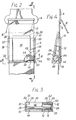
- Figure 2 is a partly cut-away elevational view of a safety belt stop shown in Figure 1 on an enlarged scale;
- Figure 3 is a sectional view along the line III-III of Figure 2;
- Figure 4 is a sectional view along the line IV-IV of Figure 2; and
- Figure 5 shows a view similar to Figure 2, but of a modified safety belt stop.
- Figure 1 shows an inertia-
reel safety belt 11 in a motor vehicle. One end (not shown) is secured to a first lower anchorage in the floor of the vehicle to one side and immediately behind a vehicle seat 1. Afirst run 7 of thebelt 11 passes across the lap of the occupant of the seat 1 to a loop of abuckle 2 secured to a secondlower anchorage 3 fixed to the vehicle's structure. Asecond run 6 passes diagonally across the occupant's chest to aguide 4 fixed to an upper anchorage 5, close to the occupant's shoulder and athird run 8 passes down onto an inertia-reel unit (not shown) which is adjacent to the first anchorage. - In accordance with the invention an
adjustable stop 9 is mounted on thediagonal run 6 of thebelt 11 in a position to abut theguide 4 to prevent the tension in thebelt 11 exerted by the inertia-reel unit causing uncomfortable pressure on the chest of the user. - The
stop 9, shown in Figures 2 to 4, comprises abody 10, aslide 30 and aknurled roller 50. - The
body 10 is folded from sheet metal or moulded from plastics material and comprises a base-12 having alateral lip 14 at one end and a pair of longitudinal side-walls flange 20 along its upper edge. Eachflange 20 has alower surface 22 and aninner edge 28. The internal width of thebody 10 betweeninner faces 26 of the side-walls - Each side-
wall lip 14 is twice its height at its opposite end. The side-wall 16 has acircular hole 24, through which therod 50 may pass, adjacent to its wider end and the side-wall 18 may have acircular hole 32 aligned with thehole 24 of smaller diameter than theroller 50. - The
slide 30 comprises acentral portion 36 which fits with a small clearance between theinner edges 28 of theflanges 20 and a pair of outerlongitudinal flanges 38 which fit with a small clearance between theinner faces 26 of the side-walls slide 30 has alateral lip 46 along one end and a parallel,lateral wall 48 extending in the same direction as thelip 46. Thelip 46 and thewall 48 form apocket 34 for receiving theknurled roller 50. - In use, the
body 10 is first fitted to thediagonal run 6 of thesafety belt 11 adjacent to theguide 4. Thebody 10 is positioned around therun 6 such that the face-of thebelt 11 close to the user is in contact with thebase 12 and the shorter ends of the side-walls guide 4. Theslide 30 is inserted between the side-walls body 10 such that thelip 46 on theslide 30 is adjacent to thelip 14 of thebase 12 and thepocket 34 is aligned with thehole 24 in the side-wall 16. The knurledroller 50 is then inserted through thehole 24 to lie in thepocket 34 adjacent to therun 6 of thebelt 11. The stop may now be moved in either direction along therun 6 by gripping theslide 30 and thebody 10 between thumb and forefinger to maintain thelip 14 on thebody 10 in alignment with thelip 46 on theslide 30. Theknurled roller 50 is free to rotate in thepocket 34 and aid the movement of thebelt 11 through the stop. - The
stop 9 is next positioned close to theguide 4 and locked to thebelt 11 by sliding theslide 30 through thebody 10 until theroller 50 grips thebelt 11 and theflanges 38 of theslide 30 contact thelower surfaces 22 of theflanges 20. The tension in thesafety belt 11 exerted by the inertia-reel assembly unit now pulls the stop against theguide 4 and the force is transmitted to theguide 4, thus preventing the pressure upon the user's chest. - To release the
stop 9 from therun 6 of thebelt 11 theslide 30 is moved through thebody 10 in a direction away from theguide 4 until theknurled roller 50 is free from thebelt 11 which may then pass through thestop 9 and onto the reel in the usual manner. The movement of theslide 30 through thebody 10 in this direction is limited by contact between thelip 14 on thebase 12 and theroller 50. - To remove the
stop 9 from therun 6 theroller 50 is aligned with thehole 24 and removed from thepocket 34. If asmaller hole 32 is provided a suitable instrument (not shown) may be inserted therethrough to eject theroller 50. Theslide 30 andbody 10 may then be removed from therun 6 of thebelt 11. - In a modified
stop 9 shown in Figure 5, thelip 14 is omitted and eachflange 20 of the side-walls wall stop 21. Thecentral portion 36 of theslide 30 has a correspondingly-shaped portion of decreasedwidth 37 which formsshoulders 39. The movement of theslide 30 in thebody 10 is limited by abutment ofshoulders 39 of theslide 30 uponedges 25 of thestops 21. - It should be noted that in both the embodiment and its modification the surfaces of the
stop 9 which contact thesafety belt 11 similar to surfaces of conventional safety belt fittings and should not, therefore cause any unacceptable deterioration of thebelt 11.
Claims (12)
Priority Applications (1)
| Application Number | Priority Date | Filing Date | Title |
|---|---|---|---|
| AT80302622T ATE5944T1 (en) | 1979-08-03 | 1980-07-31 | SEAT BELT LOCKING DEVICE. |
Applications Claiming Priority (2)
| Application Number | Priority Date | Filing Date | Title |
|---|---|---|---|
| GB7927186A GB2055945B (en) | 1979-08-03 | 1979-08-03 | Safety belt stop |
| GB7927186 | 1979-08-03 |
Publications (2)
| Publication Number | Publication Date |
|---|---|
| EP0026564A1 true EP0026564A1 (en) | 1981-04-08 |
| EP0026564B1 EP0026564B1 (en) | 1984-01-25 |
Family
ID=10506987
Family Applications (1)
| Application Number | Title | Priority Date | Filing Date |
|---|---|---|---|
| EP80302622A Expired EP0026564B1 (en) | 1979-08-03 | 1980-07-31 | Safety belt stop |
Country Status (5)
| Country | Link |
|---|---|
| EP (1) | EP0026564B1 (en) |
| AT (1) | ATE5944T1 (en) |
| DE (1) | DE3066279D1 (en) |
| GB (1) | GB2055945B (en) |
| IE (1) | IE49965B1 (en) |
Cited By (7)
| Publication number | Priority date | Publication date | Assignee | Title |
|---|---|---|---|---|
| FR2656844A1 (en) * | 1990-01-05 | 1991-07-12 | Mordchelles Regnier Georges | STOPPING ADJUSTMENT OF A SLIDING ELEMENT. |
| US20110140405A1 (en) * | 2009-11-02 | 2011-06-16 | Amsafe Commercial Products, Inc. | Devices for adjusting tension in seat belts and other restraint system webs, and associated methods |
| US9775410B2 (en) | 2014-12-16 | 2017-10-03 | Shield Restraint Systems, Inc. | Web adjusters for use with restraint systems and associated methods of use and manufacture |
| US9814282B2 (en) | 2016-02-02 | 2017-11-14 | Shield Restraint Systems, Inc. | Harsh environment buckle assemblies and associated systems and methods |
| US10086795B2 (en) | 2015-10-02 | 2018-10-02 | Shield Restraint Systems, Inc. | Load indicators for personal restraint systems and associated systems and methods |
| US10604259B2 (en) | 2016-01-20 | 2020-03-31 | Amsafe, Inc. | Occupant restraint systems having extending restraints, and associated systems and methods |
| US10611334B2 (en) | 2017-02-07 | 2020-04-07 | Shield Restraint Systems, Inc. | Web adjuster |
Families Citing this family (4)
| Publication number | Priority date | Publication date | Assignee | Title |
|---|---|---|---|---|
| ES2216475T3 (en) * | 1998-10-21 | 2004-10-16 | Rene Rosse | DEVICE FOR VEHICLE SAFETY BELT. |
| US9022483B2 (en) | 2012-06-07 | 2015-05-05 | Shield Restraint Systems, Inc. | Seatbelt buckle tongue assembly |
| US9119445B2 (en) | 2013-02-19 | 2015-09-01 | Amsafe, Inc. | Buckle assemblies with lift latches and associated methods and systems |
| US9277788B2 (en) | 2013-02-19 | 2016-03-08 | Amsafe, Inc. | Dual release buckle assemblies and associated systems and methods |
Citations (10)
| Publication number | Priority date | Publication date | Assignee | Title |
|---|---|---|---|---|
| DE7626027U1 (en) * | 1976-08-19 | 1976-12-23 | Lahner, Franz, 8183 Rottach-Egern | AUTOMATIC SEAT BELT |
| DE2551642A1 (en) * | 1975-11-18 | 1977-06-02 | Reiner G Szperkowski | Tugging and pressure eliminator for safety belts - has additional clamp in front of reorientating buckle or rolling up mechanism |
| DE7638852U1 (en) * | 1976-12-11 | 1977-07-07 | Meyer, Ernst, 6051 Dietzenbach- Steinberg | CLAMP FOR AUTOMATIC SEAT BELT |
| DE2620411A1 (en) * | 1976-05-08 | 1977-11-24 | Hans W Dipl Ing Funk | Seat belt webbing gripping device - consists of two L:shaped parts which mesh together using protrusion and slot arrangement |
| DE2635349A1 (en) * | 1976-08-03 | 1978-02-09 | Yorck Talbot | Vehicle seat-belt stop plate - has adjustable pair of lateral yokes slidable on retracted length of seat-belt webbing |
| DE2047706B2 (en) * | 1970-09-28 | 1978-05-24 | Wolf-Dieter 7071 Lindach Klink | Seat belts for vehicle occupants |
| FR2381531A1 (en) * | 1977-02-23 | 1978-09-22 | Laporte Claude | Lock for vehicle safety belt - has roller movable in cage to jam against belt at top of ramp to relieve pressure from belt reel |
| DE2730510A1 (en) * | 1977-07-06 | 1979-01-25 | Karl Rittirsch | Automatic safety belt clip - is fitted after guide eye to relieve tension and has releasable jaws to allow rewind |
| DE7824661U1 (en) * | 1978-08-18 | 1979-02-15 | Schroether, Alfred, 8901 Koenigsbrunn | LOCKING BARS FOR SAFETY BELTS IN MOTOR VEHICLES |
| DE2751984A1 (en) * | 1977-11-22 | 1979-05-23 | August Paul Dipl Ing Dr H C | Tension relief device for seat belt with automatic retractor - consists of spring-loaded clip attached to webbing underneath strap deflecting fitting |
-
1979
- 1979-08-03 GB GB7927186A patent/GB2055945B/en not_active Expired
-
1980
- 1980-07-31 EP EP80302622A patent/EP0026564B1/en not_active Expired
- 1980-07-31 DE DE8080302622T patent/DE3066279D1/en not_active Expired
- 1980-07-31 AT AT80302622T patent/ATE5944T1/en not_active IP Right Cessation
- 1980-08-05 IE IE1628/80A patent/IE49965B1/en unknown
Patent Citations (10)
| Publication number | Priority date | Publication date | Assignee | Title |
|---|---|---|---|---|
| DE2047706B2 (en) * | 1970-09-28 | 1978-05-24 | Wolf-Dieter 7071 Lindach Klink | Seat belts for vehicle occupants |
| DE2551642A1 (en) * | 1975-11-18 | 1977-06-02 | Reiner G Szperkowski | Tugging and pressure eliminator for safety belts - has additional clamp in front of reorientating buckle or rolling up mechanism |
| DE2620411A1 (en) * | 1976-05-08 | 1977-11-24 | Hans W Dipl Ing Funk | Seat belt webbing gripping device - consists of two L:shaped parts which mesh together using protrusion and slot arrangement |
| DE2635349A1 (en) * | 1976-08-03 | 1978-02-09 | Yorck Talbot | Vehicle seat-belt stop plate - has adjustable pair of lateral yokes slidable on retracted length of seat-belt webbing |
| DE7626027U1 (en) * | 1976-08-19 | 1976-12-23 | Lahner, Franz, 8183 Rottach-Egern | AUTOMATIC SEAT BELT |
| DE7638852U1 (en) * | 1976-12-11 | 1977-07-07 | Meyer, Ernst, 6051 Dietzenbach- Steinberg | CLAMP FOR AUTOMATIC SEAT BELT |
| FR2381531A1 (en) * | 1977-02-23 | 1978-09-22 | Laporte Claude | Lock for vehicle safety belt - has roller movable in cage to jam against belt at top of ramp to relieve pressure from belt reel |
| DE2730510A1 (en) * | 1977-07-06 | 1979-01-25 | Karl Rittirsch | Automatic safety belt clip - is fitted after guide eye to relieve tension and has releasable jaws to allow rewind |
| DE2751984A1 (en) * | 1977-11-22 | 1979-05-23 | August Paul Dipl Ing Dr H C | Tension relief device for seat belt with automatic retractor - consists of spring-loaded clip attached to webbing underneath strap deflecting fitting |
| DE7824661U1 (en) * | 1978-08-18 | 1979-02-15 | Schroether, Alfred, 8901 Koenigsbrunn | LOCKING BARS FOR SAFETY BELTS IN MOTOR VEHICLES |
Cited By (9)
| Publication number | Priority date | Publication date | Assignee | Title |
|---|---|---|---|---|
| FR2656844A1 (en) * | 1990-01-05 | 1991-07-12 | Mordchelles Regnier Georges | STOPPING ADJUSTMENT OF A SLIDING ELEMENT. |
| EP0437138A1 (en) * | 1990-01-05 | 1991-07-17 | Georges Mordchelles-Regnier | Adjustment stop for a sliding element |
| US20110140405A1 (en) * | 2009-11-02 | 2011-06-16 | Amsafe Commercial Products, Inc. | Devices for adjusting tension in seat belts and other restraint system webs, and associated methods |
| US8393645B2 (en) * | 2009-11-02 | 2013-03-12 | Amsafe Commercial Products, Inc. | Devices for adjusting tension in seat belts and other restraint system webs, and associated methods |
| US9775410B2 (en) | 2014-12-16 | 2017-10-03 | Shield Restraint Systems, Inc. | Web adjusters for use with restraint systems and associated methods of use and manufacture |
| US10086795B2 (en) | 2015-10-02 | 2018-10-02 | Shield Restraint Systems, Inc. | Load indicators for personal restraint systems and associated systems and methods |
| US10604259B2 (en) | 2016-01-20 | 2020-03-31 | Amsafe, Inc. | Occupant restraint systems having extending restraints, and associated systems and methods |
| US9814282B2 (en) | 2016-02-02 | 2017-11-14 | Shield Restraint Systems, Inc. | Harsh environment buckle assemblies and associated systems and methods |
| US10611334B2 (en) | 2017-02-07 | 2020-04-07 | Shield Restraint Systems, Inc. | Web adjuster |
Also Published As
| Publication number | Publication date |
|---|---|
| ATE5944T1 (en) | 1984-02-15 |
| IE801628L (en) | 1981-02-03 |
| DE3066279D1 (en) | 1984-03-01 |
| IE49965B1 (en) | 1986-01-22 |
| EP0026564B1 (en) | 1984-01-25 |
| GB2055945A (en) | 1981-03-11 |
| GB2055945B (en) | 1983-04-13 |
Similar Documents
| Publication | Publication Date | Title |
|---|---|---|
| EP0026564A1 (en) | Safety belt stop | |
| US5084946A (en) | Quick disconnect connector | |
| US4685741A (en) | Child passenger securing apparatus | |
| US5154446A (en) | Shoulder belt adjustment device for seat belt systems | |
| US5088160A (en) | Lap belt webbing adjuster | |
| US6312015B1 (en) | Clamp for retractor belt | |
| EP0597957B1 (en) | Seat belt shoulder strap adjustment guide apparatus | |
| US3982769A (en) | Safety belts | |
| US4878271A (en) | Tongue assembly | |
| US3929351A (en) | Comfort clip for a shoulder belt of a vehicle occupant restraint belt system | |
| EP0043430B1 (en) | Adjustable self-locking tongue plate for seat belt | |
| EP0113173A2 (en) | Free-falling, self-locking adjustable tip assembly | |
| US4588207A (en) | Free-falling, self-locking adjustable tip assembly | |
| US5086548A (en) | Buckle device for seatbelt system | |
| US4962572A (en) | Tongue assembly | |
| US4871190A (en) | Safety apparatus | |
| CA1122942A (en) | Buckle assembly for continuous loop occupant restraint belt system | |
| US5328249A (en) | Seat belt system | |
| US4878272A (en) | Tongue assembly | |
| US4482187A (en) | Belt guide structure | |
| US4912818A (en) | Belt adjusting apparatus | |
| US5005910A (en) | Apparatus for restricting relative movement of belt portions | |
| EP0952047B1 (en) | Buckle for a seat belt | |
| EP0205037A1 (en) | Safety belt buckle | |
| US3877115A (en) | Pushbutton release connector |
Legal Events
| Date | Code | Title | Description |
|---|---|---|---|
| PUAI | Public reference made under article 153(3) epc to a published international application that has entered the european phase |
Free format text: ORIGINAL CODE: 0009012 |
|
| AK | Designated contracting states |
Designated state(s): AT BE CH DE FR LI SE |
|
| 17P | Request for examination filed |
Effective date: 19810829 |
|
| RAP1 | Party data changed (applicant data changed or rights of an application transferred) |
Owner name: JOHNSON, COLIN BARCLAY |
|
| GRAA | (expected) grant |
Free format text: ORIGINAL CODE: 0009210 |
|
| AK | Designated contracting states |
Designated state(s): AT BE CH DE FR LI SE |
|
| PG25 | Lapsed in a contracting state [announced via postgrant information from national office to epo] |
Ref country code: SE Effective date: 19840125 Ref country code: BE Effective date: 19840125 Ref country code: AT Effective date: 19840125 |
|
| REF | Corresponds to: |
Ref document number: 5944 Country of ref document: AT Date of ref document: 19840215 Kind code of ref document: T |
|
| REF | Corresponds to: |
Ref document number: 3066279 Country of ref document: DE Date of ref document: 19840301 |
|
| ET | Fr: translation filed | ||
| PGFP | Annual fee paid to national office [announced via postgrant information from national office to epo] |
Ref country code: FR Payment date: 19840629 Year of fee payment: 5 |
|
| PGFP | Annual fee paid to national office [announced via postgrant information from national office to epo] |
Ref country code: CH Payment date: 19840713 Year of fee payment: 5 |
|
| PGFP | Annual fee paid to national office [announced via postgrant information from national office to epo] |
Ref country code: DE Payment date: 19840924 Year of fee payment: 5 |
|
| PLBE | No opposition filed within time limit |
Free format text: ORIGINAL CODE: 0009261 |
|
| STAA | Information on the status of an ep patent application or granted ep patent |
Free format text: STATUS: NO OPPOSITION FILED WITHIN TIME LIMIT |
|
| 26N | No opposition filed | ||
| PG25 | Lapsed in a contracting state [announced via postgrant information from national office to epo] |
Ref country code: LI Effective date: 19860731 Ref country code: CH Effective date: 19860731 |
|
| PG25 | Lapsed in a contracting state [announced via postgrant information from national office to epo] |
Ref country code: FR Free format text: LAPSE BECAUSE OF NON-PAYMENT OF DUE FEES Effective date: 19870331 |
|
| REG | Reference to a national code |
Ref country code: CH Ref legal event code: PL |
|
| PG25 | Lapsed in a contracting state [announced via postgrant information from national office to epo] |
Ref country code: DE Effective date: 19870401 |
|
| REG | Reference to a national code |
Ref country code: FR Ref legal event code: ST |