EP0026107A2 - Method and apparatus for cutting continuous fibrous material - Google Patents
Method and apparatus for cutting continuous fibrous material Download PDFInfo
- Publication number
- EP0026107A2 EP0026107A2 EP80303349A EP80303349A EP0026107A2 EP 0026107 A2 EP0026107 A2 EP 0026107A2 EP 80303349 A EP80303349 A EP 80303349A EP 80303349 A EP80303349 A EP 80303349A EP 0026107 A2 EP0026107 A2 EP 0026107A2
- Authority
- EP
- European Patent Office
- Prior art keywords
- knives
- rotor
- rotors
- another
- cutting
- Prior art date
- Legal status (The legal status is an assumption and is not a legal conclusion. Google has not performed a legal analysis and makes no representation as to the accuracy of the status listed.)
- Granted
Links
- 238000005520 cutting process Methods 0.000 title claims abstract description 48
- 238000000034 method Methods 0.000 title claims abstract description 21
- 239000002657 fibrous material Substances 0.000 title abstract 2
- 239000000463 material Substances 0.000 claims abstract description 36
- 230000002093 peripheral effect Effects 0.000 claims description 5
- 210000003127 knee Anatomy 0.000 claims description 2
- 230000001050 lubricating effect Effects 0.000 claims description 2
- 239000012530 fluid Substances 0.000 claims 1
- 239000000835 fiber Substances 0.000 description 33
- 230000009471 action Effects 0.000 description 8
- 239000003365 glass fiber Substances 0.000 description 6
- 230000007246 mechanism Effects 0.000 description 6
- 238000004519 manufacturing process Methods 0.000 description 5
- 238000004513 sizing Methods 0.000 description 4
- 238000009987 spinning Methods 0.000 description 4
- 239000002184 metal Substances 0.000 description 3
- 238000012545 processing Methods 0.000 description 3
- 230000008439 repair process Effects 0.000 description 3
- 238000011161 development Methods 0.000 description 2
- 230000000694 effects Effects 0.000 description 2
- 239000011521 glass Substances 0.000 description 2
- 239000012943 hotmelt Substances 0.000 description 2
- 238000012423 maintenance Methods 0.000 description 2
- 230000002250 progressing effect Effects 0.000 description 2
- 230000000750 progressive effect Effects 0.000 description 2
- OKTJSMMVPCPJKN-UHFFFAOYSA-N Carbon Chemical compound [C] OKTJSMMVPCPJKN-UHFFFAOYSA-N 0.000 description 1
- 229920000049 Carbon (fiber) Polymers 0.000 description 1
- 229920000914 Metallic fiber Polymers 0.000 description 1
- 230000002238 attenuated effect Effects 0.000 description 1
- 229910052799 carbon Inorganic materials 0.000 description 1
- 239000004917 carbon fiber Substances 0.000 description 1
- 239000010730 cutting oil Substances 0.000 description 1
- 238000013016 damping Methods 0.000 description 1
- 229920006240 drawn fiber Polymers 0.000 description 1
- 239000003623 enhancer Substances 0.000 description 1
- 230000002708 enhancing effect Effects 0.000 description 1
- 238000012840 feeding operation Methods 0.000 description 1
- 238000010438 heat treatment Methods 0.000 description 1
- 230000004048 modification Effects 0.000 description 1
- 238000012986 modification Methods 0.000 description 1
- 238000010008 shearing Methods 0.000 description 1
- 239000007787 solid Substances 0.000 description 1
- 239000007921 spray Substances 0.000 description 1
- 230000001360 synchronised effect Effects 0.000 description 1
- 238000011144 upstream manufacturing Methods 0.000 description 1
- 238000009941 weaving Methods 0.000 description 1
Images


Classifications
-
- D—TEXTILES; PAPER
- D01—NATURAL OR MAN-MADE THREADS OR FIBRES; SPINNING
- D01G—PRELIMINARY TREATMENT OF FIBRES, e.g. FOR SPINNING
- D01G1/00—Severing continuous filaments or long fibres, e.g. stapling
- D01G1/06—Converting tows to slivers or yarns, e.g. in direct spinning
- D01G1/10—Converting tows to slivers or yarns, e.g. in direct spinning by cutting
-
- Y—GENERAL TAGGING OF NEW TECHNOLOGICAL DEVELOPMENTS; GENERAL TAGGING OF CROSS-SECTIONAL TECHNOLOGIES SPANNING OVER SEVERAL SECTIONS OF THE IPC; TECHNICAL SUBJECTS COVERED BY FORMER USPC CROSS-REFERENCE ART COLLECTIONS [XRACs] AND DIGESTS
- Y10—TECHNICAL SUBJECTS COVERED BY FORMER USPC
- Y10S—TECHNICAL SUBJECTS COVERED BY FORMER USPC CROSS-REFERENCE ART COLLECTIONS [XRACs] AND DIGESTS
- Y10S83/00—Cutting
- Y10S83/913—Filament to staple fiber cutting
-
- Y—GENERAL TAGGING OF NEW TECHNOLOGICAL DEVELOPMENTS; GENERAL TAGGING OF CROSS-SECTIONAL TECHNOLOGIES SPANNING OVER SEVERAL SECTIONS OF THE IPC; TECHNICAL SUBJECTS COVERED BY FORMER USPC CROSS-REFERENCE ART COLLECTIONS [XRACs] AND DIGESTS
- Y10—TECHNICAL SUBJECTS COVERED BY FORMER USPC
- Y10T—TECHNICAL SUBJECTS COVERED BY FORMER US CLASSIFICATION
- Y10T83/00—Cutting
- Y10T83/04—Processes
- Y10T83/0515—During movement of work past flying cutter
-
- Y—GENERAL TAGGING OF NEW TECHNOLOGICAL DEVELOPMENTS; GENERAL TAGGING OF CROSS-SECTIONAL TECHNOLOGIES SPANNING OVER SEVERAL SECTIONS OF THE IPC; TECHNICAL SUBJECTS COVERED BY FORMER USPC CROSS-REFERENCE ART COLLECTIONS [XRACs] AND DIGESTS
- Y10—TECHNICAL SUBJECTS COVERED BY FORMER USPC
- Y10T—TECHNICAL SUBJECTS COVERED BY FORMER US CLASSIFICATION
- Y10T83/00—Cutting
- Y10T83/202—With product handling means
- Y10T83/2066—By fluid current
-
- Y—GENERAL TAGGING OF NEW TECHNOLOGICAL DEVELOPMENTS; GENERAL TAGGING OF CROSS-SECTIONAL TECHNOLOGIES SPANNING OVER SEVERAL SECTIONS OF THE IPC; TECHNICAL SUBJECTS COVERED BY FORMER USPC CROSS-REFERENCE ART COLLECTIONS [XRACs] AND DIGESTS
- Y10—TECHNICAL SUBJECTS COVERED BY FORMER USPC
- Y10T—TECHNICAL SUBJECTS COVERED BY FORMER US CLASSIFICATION
- Y10T83/00—Cutting
- Y10T83/465—Cutting motion of tool has component in direction of moving work
- Y10T83/4766—Orbital motion of cutting blade
- Y10T83/4769—Work feeder mounted on tool support
- Y10T83/4772—Gripper-type feeder
-
- Y—GENERAL TAGGING OF NEW TECHNOLOGICAL DEVELOPMENTS; GENERAL TAGGING OF CROSS-SECTIONAL TECHNOLOGIES SPANNING OVER SEVERAL SECTIONS OF THE IPC; TECHNICAL SUBJECTS COVERED BY FORMER USPC CROSS-REFERENCE ART COLLECTIONS [XRACs] AND DIGESTS
- Y10—TECHNICAL SUBJECTS COVERED BY FORMER USPC
- Y10T—TECHNICAL SUBJECTS COVERED BY FORMER US CLASSIFICATION
- Y10T83/00—Cutting
- Y10T83/465—Cutting motion of tool has component in direction of moving work
- Y10T83/4766—Orbital motion of cutting blade
- Y10T83/4795—Rotary tool
- Y10T83/483—With cooperating rotary cutter or backup
Definitions
- the present invention relates generally to a method and apparatus for cutting funicular material such as tow and monofilaments into short lengths.
- Knives travelling at high speed striking an elastomeric surface, bedplate or other knives create turbulence, impact noise, and vibration.which produce a highly objectionable environment around cutting equipment. Also, high speed impact results in fiber fusing and generally poor performance. Additionally, knives are usually made of hardened materials which are subject to fracture and present a safety hazard to both fiber manufacturing and fiber usage personnel. In this way, a fractured knife could possibly damage fiber processing machinery. Fractured knives cause multiple lengths of staple, poor fiber performance and machine down time.
- the known cutting machines have not been capable of handling very high rates of feed while incorporating a slow cut, nonfusing, flying shear action.
- the glass fiber and hot melt fiber industries have been hamstrung by the lack of such equipment and have been forced to attenuate or stretch the semi-molten fibers at quite low rates of feed or alternatively, to employ separate heating steps.
- a cutting machine capable of at least 20,000 feet per minute would make intermediate energy wasting fiber processing steps unnecessary.
- the hot melt fibers could then go from a reactor to cut staple in one step and the glass fibers, attenuated by the cutter itself, could be run at the maximum speeds permitted by the spinning equipment. In this case, the cutter would no longer be the production bottleneck, and development could begin anew on increasing the spinning speeds.
- Present glass fiber cutting equipment takes into account the rapid dulling of the knives and the necessity for short runs and excessive down time.
- The.industry is in great need of equipment which will increase runs from hours to days or even weeks.
- present metal fiber cutting equipment does not "cut” at all, but instead pulls the fibers in two. Short cut wire and monofilament staple are usually cut on slow punch press cutters. These procedures result in a random staple length having poor end conditions.
- an object of the present invention is to reduce the high impact at the cut point and thereby reduce the possibility of knife breakage and also reduce vibration and noise.
- a further object of the present invention is to provide a cutter which will not fuse the fibers together due to heat buildup at very high rates of feed.
- a still further object of the present invention is to provide a cutter which will produce uniform and highly accurate cut lengths.
- Another object of the present invention is to produce a cutter which sharpens the knives as the cutter is in operation.
- This self-sharpening feature has the advantages of reducing maintenance and increasing running time for the apparatus.
- a cutter comprises two closely spaced members; preferably rotors or discs facing one another. At least one of the rotors has a plurality of knives attached to its surface in a pinwheel configuration. In a preferred embodiment, both rotors have knives affixed to their respective surfaces in sliding contact engagement. One of the rotors preferably has at least one less knife than the other rotor. The rotor with the lesser number of knives rotates slightly faster than the other rotor.
- Attenuation as in the production of glass or drawn fibers
- tension on the tow band is accomplished by weaving the tow band zigzag fashion into the spaces formed by the tapered knives on the two relatively sliding pinwheels. In this way, tow band pulling tension begins at the point of entry into the pinwheel niche proper and the tow band can slide down between the knives.
- the tow tension builds as each set of knives comes nearer to a configuration of cutting mesh.
- the first set of knives (at tow band entry) is in maximum mis-mesh while the intermediate sets of knives are in varying degrees of mis-mesh, and the last set of knives to touch the tow is in complete cutting mesh..Cutting then occurs and the cut bundle, urged by centrifugal force and air (or other suitable medium), escapes from the machine and is flung into a product collector chute.
- the present invention is capable of cutting substantially all fibers, but is especially adapted to glass, carbon, metallic and other fibers including wire and different generic monofilaments that, for one reason or another, have heretofore been considered exceedingly difficult to cut.
- the principle,of conventional scissors has been employed at the point of severance of the present invention in a novel manner.
- the scissors action provides a certainty of cut and also a built-in self-sharpening feature for the apparatus that insures that many additional hours of satisfactory operation can be expected before normal sharpening of the knives by grinding is necessary.
- the knives grind themselves much like a butcher sharpens his knife.
- a multiplicity of filaments 101 issue from each of a series of forming spinnerettes 102 and pass over a finish applicator 103.
- the filaments gather together into a multiplicity of tow bands 104, and each partially encircles a respective feed roll 105.
- Each tow band 104 establishes a linear speed and gathers into a larger tow band 106 comprised of the several tow bands 104 (formed in a similar way), which larger tow band 106 proceeds thence through a conventional tensioning mechanism 107.
- the tow band 106 is fed into a cutter 108 at the topmost or twelve o'clock position 109 and is gripped by and moves with a rotor head 110 for approximately 180°, or just before the six o'clock position 111 (see also Fig. 7). Just before the six o'clock position 111, the tow band 106 is cut into staple 112 of a predetermined length which is discharged into a housing 113 and exits therefrom by way of a chute 114 to be carried away by an air conveyor (airveyor) tube, a belt conveyor, or other apparatus (not shown).
- an air conveyor airveyor
- the conventional tensioning mechanism 107 is preferably arranged between the point of entry into the rotors 110 and the feed rolls 105. In this way, by passing the tow snake-like over and under a plurality of fixed rolls 176 with a movable final roll 177, the tension on the tow being fed into the cutting mechanism may be varied. Depending upon the variation in tension of the tow as a result of the forming and/or feeding operation, a tensioning mechanism may or may not be necessary.
- feed rolls 105 One of the functions of the feed rolls 105, in prior processing hardware has been to establish a feed or tow speed. Such establishment of a feed speed is not necessary in the present invention because of the ability of the rotors to grip and tension the tow during cutting as explained subsequently.
- a preferred embodiment of the cutter 108 is more readily understood with reference to Fig. 2 wherein a frame 120 supports a double pillow block 121 and a drive motor 122.
- the double pillow block 121 receives an inner shaft 123 and an outer sleeve 124.
- the inner shaft 123 has an outboard rotor 125 at one end and an outer timing sheave 127 at the other end.
- the outer sleeve 124 has an inboard rotor 126 mounted at one end and an inner'timing sheave 128 at the other end.
- the outer timing sheave 127 and the inner timing sheave 128 are driven by the drive motor 122 through respective drive sheaves 129 and 130 and drive belts 131 and 132. If necessary, a belt tensioning device 100 may be provided (see Fig. 1).
- a plurality of knives 133 of a suitable material are fixed to the inner rotor 126 and likewise a plurality of knives 133 are fixed to the outer rotor 125 in a quantity which is sufficient to divide the rotor cutting circle into a suitable number of spaces with the spaces defining the desired length of cut.
- the knives could be arranged with random or equal spacing depending upon the type of material and the length of cut desired.
- An external hub plate 138 is secured to the inner shaft 123 and applies adjustable pressure to the rotor 125 through, a resilient pressure washer 137.
- the external hub plate 138 is also rotatably fixed both to the rotor 125 and to the inner shaft 123.
- the pressure washer 137 is loaded against the rotor 125 by a thrust bearing 134 (provided between the sheaves 127, 128), a thrust collar 135 and an adjustable locknut 136.
- a thrust bearing 134 provided between the sheaves 127, 128, a thrust collar 135 and an adjustable locknut 136.
- Resilient mounting within one of the rotors 125, 126 is also desirable in order to prevent damage to-the knives.
- Various elastomeric arrangements may be utilized to permit a slight axial movement of the knives of one rotor.
- the end of the press fit pin is preferably ground flush after assembly.
- Air holes 178 may be provided near the shaft 123 at the center of either rotor to permit the rotor unit to become a centrifugal fan. These air holes would aid the centrifugal force acting on the cut fiber and tend to blow or fling the cut fiber away from the rotors and toward the chute 114. The air holes could also be provided with forced air from an external source (not shown) to further enhance the effect. If desired, a cover plate 179 having holes 180 corresponding to the holes 178 can be rotatably mounted with respect to the one rotor so as to permit a control or damping of the amount of air supplied through the air holes 178.
- sizing or finish can be controllably introduced into the air (drawn or forced) through the air holes.
- a channel 181 may be provided about the holes 180 on the cover plate 179.
- a suitable conduit 182 would supply a metered amount of sizing or finish to the channel with the sizing or finish then supplied to the rotors through the air holes 178.
- the sizing or finish would enhancer the performance of the cut staple for its particular end use and would also aids in lubricating the sliding plurality of knives affixed to the rotors.
- one of the rotors has one or more additional knives than the other rotor. If the rotors each had the same number of knives arranged in an equally spaced relationship on each of the rotors, at a certain point during the co-rotation of the rotors the outermost end of the knives on one rotor would coincide with the outermost end of the knives on the other rotor. At this time, there would be no opening into which the fiber to be cut could be fed.
- the rotors be timed by the drive sheaves 129 and 130, the drive belts 131 and 132, and the timing sheaves 127 and 1 28 or by other suitable-aoparatus such as gearing, so that the rotor with the lesser number of knives rotates faster than the rotor with the greater number of knives.
- the difference in speed is preferably such that the same number of knives on each rotor pass by a given point near the periphery of the co-rotating rotors in a given period of time. Both rotors are turning in the same direction and therefore the rotor with the lesser number of knives is constantly overtaking the rotor with the greater number of knives in a timed ratio. In this way, the individual knives of one rotor may be said to be advancing with respect to the knives of the other rotor (preferably one knife per revolution of the rotor).
- each of the knives 133 on each rotor, shewn ing Fig. 3, are slanted so they do not point to the rotor centor and are therefore not true spokes.
- each of the knives is preferably arranged so that it forms an angle of other than 90° with a tangent line at the periphery of the rotor.
- the knives 133 together form a pinwheel configuration on the surface of the rotor and present a maze of crossing points.
- the knives of each rotor are arranged in divergent directions with respect to the adjacent knives of the other rotor so as to form the scissors-like arrangement. This is true because the knives on one rotor are slanted in a.direction opposite to those on the other rotor when assembled with their respective knives facing each other. If each rotor is viewed separately, however, looking toward the surface with the knives, the knives are preferably oriented in the same direction except that one of rotors contains at least one more knife than the other rotor.
- the surfaces of all of the knives of each rotor are preferably ground in a flat plane.
- the slant causes any one knife on the rotor 125 to cross three knives on the rotor 126, in the illustrated embodiment of Fig. 7.
- Whether the knives of one rotor cross one, two, three or more knives of the other rotor depends upon the configuration (i.e. spacing, angle of orientation, thickness, etc.) of the knives of the rotors. Therefore it can be seen that with sixty knives on one rotor providing a three quarter inch cut, (see Fig. 7) the embodiment has a maze of one hundred and eighty touch points constantly sliding along the edges of the many knives to sharpen them.
- the finish may be designed to act as a cutting oil further enhancing the sharpening action.
- the tow band is woven snake-like between the out-of-mesh knives at the twelve o'clock position.
- the tension of the mechanism 107 along with the gripping of the tow band by the adjacent knives of the rotors at about the nine o'clock position, causes the tow band to be pulled down between the out-of-mesh knives.
- the knives come into closer mesh with one another until the tow is finally cut and free to be thrown off radially.
- the rotors have a different number of knives, one rotor preferably having one less knife than the other and rotating at a faster rate of linear speed so as to have every knife mesh in each revolution as every knife of the faster rotor advances with respect to an adjacent knife of the slower rotor during each revolution.
- the knives are seen in a maximum out-of-mesh position. This point is identified as the "twelve o'clock". position (with reference to Fig. 1) and is the point where the fiber is fed into the cutter. In this position, the fiber can be pulled down between the knives serpentine-like by the tension on the tow band.
- Fig. 5 labeled the "nine o'clock” position
- the knives are shown approaching mesh.
- the fiber bundle is being squeezed and the magnitude of pull which can be exerted on the tow bundle by the several sets of semi-meshing knives is more fully understood.
- Fig. 6 labeled the “six o'clock” position
- the knives are in full mesh, the faster rotor with the fewer knives having overtaken the slower rotor with more knives.
- the tow band previously having zigzagged snake-like to avoid being severed, has now passed the point where the two knives have meshed firmly in a scissors-like manner and has been severed into staple of a length equivalent to the spacing between the generally spoke-like knives.
- the view of Fig. 10 can also be considered as illustrating the progressive movement of a single knife of one rotor toward and then beyond an adjacent knife of the other rotor. In this way, the one knife may be seen to advance with respect to the other knife of the other rotor during the relative rotation of the rotors.
- the view of Fig. 10 can be considered to show the relative movement of individual knives of the rotors with respect to one another much as a properly adjusted strobe light and camera arrangement shows the relative positions of the knives moving relative to one another about the rotors during rotation.
- FIG. 11 With reference to Fig. 11, the relative movement of the knives of one rotor with respect to the knives of the other. rotor is illustrated in a manner similar to that of Fig. 10 but with an axial view rather than a radial view.
- the curved periphery of the rotors has been illustrated in a linear view. Moving from right to left, the outer ends of the knives are directed upwardly and slant away from one another to provide the "V" groove entrance (see also Fig. 8). At the twelve o'clock position, the radially outermost flat portions of the knives of the rotors are in maximum mis-mesh.
- the radially outermost flat portions of the knives first engage one another to prevent the tow band from escaping between the knives and subsequently cut the tow band (at least by the six o'clock position).
- the cut tow band segments are then free to fly radially outwardly from the rotors.
- Fig. 3 is taken along the section 3-3 in Fig. 2 which cuts through one set of knives looking into the other set.
- the angles of the knives and their scissors-like shear arrangement become clear when this assembly is analyzed especially with reference to Figs. 10 and 11. It will be noted that neither set of knives is arranged so that the knives will pass through the center or hub of the rotor. Therefore, they are not true spokes.
- each rotor is tangential with respect to an imaginary circle concentric about the axis of the rotor with the radius of the imaginary circle depending upon the angle of inclination of the knives.
- the angles have been designed to give the two sets of knives a scissors-like shearing effect at their ideal cutting point.
- Development work in an attempt to determine the optimum parameters for general use, points to knives set at an angle of 15° to a radial line, making a total scissor angle of 30° between the two knives at peripheral contact. It is to be understood that this angle will vary gradually as the rotors turn.
- knives set in the rotor at 10° to the planar surface and sharpened with a 10° rake angle also appear near the optimum for general use.
- the shape of the rotors and the knives preferably cooperate with one another to form a "V" groove as best seen in Fig. 9.
- Each of the knives 133 is preferably provided with an angularly sloping section 160 at the outer end of the knife. These sections 160 s'lope toward the periphery of the rotors 125, 126 to form a substantially "V" shaped groove having an angular dimension of, for example, about sixty degrees and more preferably about thirty degrees.
- the knives 133 At the base of the "V" the knives 133 have a radius section or knee 161 which forms an obliquely curved bottom to the "V".
- the angular slopes 160 and the radii 161 on the knives are designed especially to cooperate to collect any straying filaments and direct them into the rounded crevice of the "V" groove in zigzag fashion where the filaments are urged further between the sets of rotating knives ready for severing.
- a second embodiment of a cutter according to the present invention is illustrated.
- a single rotor 126 contains a plurality of knives 133 which mesh with a suitable wear-resistant surface 141, on a rotor 140.
- the surface 141 is pressed against the knives 133 of the companion rotor 126 by a resilient device 142 to insure contact in the cutting zone.
- the rotor 126 is mounted, as in the'previous arrangement, on a sleeve 124 which carries a shaft 123 that mounts a rotor 140.
- a thrust bearing 144 is aligned by a hub 145 mounted on a wobble shaft 146.
- the wobble shaft 146 is actuated by a force (the arrow 147) from an external stationary source 148 to provide suitable cutting pressure between the knives 133 and the wear resistant surface 141.
- the wobble shaft 146 also provides an opening niche 143 into which the tow band can enter.
- Fig. 12 is especially adapted to cut glass fiber or materials which fracture or readily scuff apart.
- the timing of the rotors would not be as critical in this embodiment since the knives would set down on the fiber, grip it firmly, and then scrape-along the companion rotor surface under pressure until the tow band has severed.
- the knives on such a modification would obviously be very hard and the companion rotor surface would be a hardened metal or other suitable material as well.
- the wear surface would be expected to erode and would therefore be expendable. Also, the knives would require sharpening occasionally.
- FIG. 13 illustrates a further embodiment of the present invention wherein fibrous tow bands 153 are fed into hollows 154 in aligned mount shafts 149 from opposite ends of a machine, progressing thence to be cut and discharged, as previously explained, on the rotor periphery.
- This machine can be described as an "inside out” cutter.
- shafts 149, mounted in aligning bearings 150 cooperate with drive rotors 151 which carry embedded knives 152.
- the rotors 151 are drivably timed, by an apparatus similar to that in Fig.
- Fibrous tow bands 153 enter through the hollows 154 of the shafts 149 and proceed through right angle turns at 155 to an internal sloping knife channel 156.
- the tow band lies, by centrifugal force, in a circular band zigzagging between knives 152 until rotation of the rotors 151 and subsequent meshing of the knives 152 cause the tows 153 to be severed.
- the cut fiber exits at the periphery of the rotors 151 through the spaced knives 152 as cut staple 157 and is carried away by a collector chute (not shown).
- apparatus having a pair of rotors mounted off axis with respect to one another or with the knives mounted on members other than rotors. It is preferable, however, that the knives be arranged for travel in one or more continuous paths, (for example, on one or more endless belts) so that the knives of the one member are arranged in sliding contact with either a smooth surface or a plurality of knives of the other member.
- the two members are moving in the same direction at the point of sliding contact but at slightly different speeds so as to cut the material between the members.
- This action takes the tow band from the downstream machine and the cutting process on the new machine begins.
- the old machine is then removed for repairs.
- the new machine may be moved on a track or other device to the position of the old machine.
- the old machine, when repaired, is inserted back into the line to occupy the role. of a new machine waiting to be used. In this manner, no spinning line ever need be shut down for cutter repairs.
- the output conveyor (belt or air) needs to be adjustable to be used by both machines (e.g., #1 and #2).
- the length of the output staple needs to be checked and the speed of the cutter set with both the line speed and the tow band tension to procure the exact cut length desired.
- the knife pressure needs to be determined either by motor line draw versus tow size and tension or by a micrometer adjustment on the knife pressure adjustment locknut 136.
- An air cylinder or diaphragm provided with a pressure regulator, all equipment well known in the art, can be installed to monitor the knife pressure at all times after it is initially determined. Knife pressures obviously vary with changes in the generic type of fiber being cut, the desired staple length, the tow band size, and the knife material and condition.
- the tow band can now be fed into the cutter at linear speeds of 20,000 feet per minute and up.
- the tow band is clamped by knives crossing over each other along its feed-in path on the rotor circle.
- the tow band follows this path only shortly, for example, from the topmost or twelve c'clock point to near the bottommost or six o'clock point, until the timed rotors catch the tow in a squeeze between two knives.
- the tow is then severed and flung outward by centrifugal force.
- Both rotors are dynamically balanced and are running in the same direction with one rotor running only slightly faster than the other.
- the rotors are rotating at particular angular velocities but these angular velocities produce separate linear speeds at the periphery of the rotors depending upon the diameter of the rotors.
- one rotor may preferably be running at 5093 rpm, the other rotor preferably running at 5178 rpm with the machine making about 320,000 cuts per minute.
- a tow band or other funicular material is fed between a first and a second series of knives at a point of mis-mesh of the knives.
- the two sets of knives are moving in the same general direction with one set preferably moving at a faster linear speed than the other set so that the. knives of one set advance with respect to the other set.
- the tow band is first grasped between the sets of advancing knives and then cut into individual segments by the sliding relative movement of the knives.
- the knives are angled in such a manner that they trap the tow band very soon after it is introduced snake-like between the rotors and will not let centrifugal force induce the tow to escape. It is as if the scissors were outside the rim cutting toward the hub. Accordingly, the tow cannot escape being cut and is trapped and held until cutting occurs.
- the arrangement of the knives insures that any knife will always be touching at least two other knives. Hence, there is no fulcrum or seesaw loading or vibration tending to destroy the rotor or its components. In the preferred embodiment, most of the knives will be bearing on three other knives and a fifteen inch rotor cutting three quarter inch staple will provide over three square.inches of hardened knife surface constantly in bearing contact.
- the knife angle and configuration in both rotors is so arranged that at the time the tow band is cut, the knives are spaced apart at their maximum distance thus facilitating the exit of the cut staple from the rotor assembly. Additionally, the centrifugal force has now achieved its maximum, and the output of the cutter can thus be directed toward a given point for discharge, not unlike the pointing of a hose nozzle.
Landscapes
- Engineering & Computer Science (AREA)
- Textile Engineering (AREA)
- Preliminary Treatment Of Fibers (AREA)
- Manufacture, Treatment Of Glass Fibers (AREA)
Abstract
Description
- The present invention relates generally to a method and apparatus for cutting funicular material such as tow and monofilaments into short lengths.
- Problems of cutting filamentary linear materials at high rates of feed are well known in the art. Glass fibers, carbon fibers and metallic fibers, in particular, as well as all of the higher modulus synthetics are troublesome to cut into accurate, usable staple.
- Knives travelling at high speed striking an elastomeric surface, bedplate or other knives create turbulence, impact noise, and vibration.which produce a highly objectionable environment around cutting equipment. Also, high speed impact results in fiber fusing and generally poor performance. Additionally, knives are usually made of hardened materials which are subject to fracture and present a safety hazard to both fiber manufacturing and fiber usage personnel. In this way, a fractured knife could possibly damage fiber processing machinery. Fractured knives cause multiple lengths of staple, poor fiber performance and machine down time.
- Heretofore, the known cutting machines have not been capable of handling very high rates of feed while incorporating a slow cut, nonfusing, flying shear action. The glass fiber and hot melt fiber industries have been hamstrung by the lack of such equipment and have been forced to attenuate or stretch the semi-molten fibers at quite low rates of feed or alternatively, to employ separate heating steps. A cutting machine capable of at least 20,000 feet per minute would make intermediate energy wasting fiber processing steps unnecessary. The hot melt fibers could then go from a reactor to cut staple in one step and the glass fibers, attenuated by the cutter itself, could be run at the maximum speeds permitted by the spinning equipment. In this case, the cutter would no longer be the production bottleneck, and development could begin anew on increasing the spinning speeds.
- An example of a prior art cutting device is disclosed in U.S. Patent No. 3,485,120 issued on December 23, 1969, to Keith. The Keith patent discloses a cutter which has a rotating cutting reel containing knives and a rotating pressure applicator. The material is built up around the cutting reel to be forced by the pressure applicator against the knives and cut into sections equal to the distance between the knives.
- Another prior art cutting device is disclosed in U.S. Patent 2,791,274,' issued on May 7, 1957, to Rivers, Jr. The Rivers, Jr. patent discloses a rotating roll consisting of two pieces between which the fiber to be cut is trapped and rotated therewith until reciprocating knives in one piece are moved to cut the trapped fiber.
- U.S. Patent No. 3,978,751r issued on September 7, 1976, to Farmer et al discloses (in Figure 16) a center feed to a rotating camming assembly and a rotating driving disc containing a plurality of knives. The disclosure teaches rotating the driving disc and knives faster than the camming assembly. Cutting occurs when the tow band is peripherally clamped between a belt, or cam, and the knives.
- Other U.S. patents which illustrate the state of the art in staple cutting include U.S. Patent Nos. 4,014,231; 3,861,257; 3,869,268; 3,948,127; 3,557,648; 3,815,461; and 3,768,355.
- Present glass fiber cutting equipment takes into account the rapid dulling of the knives and the necessity for short runs and excessive down time. The.industry is in great need of equipment which will increase runs from hours to days or even weeks. Also, present metal fiber cutting equipment does not "cut" at all, but instead pulls the fibers in two. Short cut wire and monofilament staple are usually cut on slow punch press cutters. These procedures result in a random staple length having poor end conditions.
- Accordingly, it is a primary object of the present invention to provide a method and apparatus which cuts funicular material at a rapid rate into segments having a uniform length.
- Specifically, an object of the present invention is to reduce the high impact at the cut point and thereby reduce the possibility of knife breakage and also reduce vibration and noise.
- A further object of the present invention is to provide a cutter which will not fuse the fibers together due to heat buildup at very high rates of feed.
- A still further object of the present invention is to provide a cutter which will produce uniform and highly accurate cut lengths.
- Another object of the present invention is to produce a cutter which sharpens the knives as the cutter is in operation. This self-sharpening feature has the advantages of reducing maintenance and increasing running time for the apparatus.
- These and other objects are realized by the apparatus according to the present invention wherein a cutter comprises two closely spaced members; preferably rotors or discs facing one another. At least one of the rotors has a plurality of knives attached to its surface in a pinwheel configuration. In a preferred embodiment, both rotors have knives affixed to their respective surfaces in sliding contact engagement. One of the rotors preferably has at least one less knife than the other rotor. The rotor with the lesser number of knives rotates slightly faster than the other rotor. Attenuation (as in the production of glass or drawn fibers) or tension on the tow band (in the production of other fibers) is accomplished by weaving the tow band zigzag fashion into the spaces formed by the tapered knives on the two relatively sliding pinwheels. In this way, tow band pulling tension begins at the point of entry into the pinwheel niche proper and the tow band can slide down between the knives.
- The tow tension builds as each set of knives comes nearer to a configuration of cutting mesh. Actually, the first set of knives (at tow band entry) is in maximum mis-mesh while the intermediate sets of knives are in varying degrees of mis-mesh, and the last set of knives to touch the tow is in complete cutting mesh..Cutting then occurs and the cut bundle, urged by centrifugal force and air (or other suitable medium), escapes from the machine and is flung into a product collector chute.
- The present invention is capable of cutting substantially all fibers, but is especially adapted to glass, carbon, metallic and other fibers including wire and different generic monofilaments that, for one reason or another, have heretofore been considered exceedingly difficult to cut. The principle,of conventional scissors has been employed at the point of severance of the present invention in a novel manner. The scissors action provides a certainty of cut and also a built-in self-sharpening feature for the apparatus that insures that many additional hours of satisfactory operation can be expected before normal sharpening of the knives by grinding is necessary. In the present invention, the knives grind themselves much like a butcher sharpens his knife.
- Preferred embodiments of a cutter according to the present invention will be described with reference to the accompanying drawings wherein like members bear like reference numerals and wherein:
- Fig. 1 is a schematic front elevational view of a cutter according to the present invention showing the cutter in conjunction with the feed and other ancillary fiber manufacturing and handling equipment;
- Fig. 2 is a sectional elevational view looking downstream of the fiber feed taken along Line 2-2 of Fig. 1;
- Fig. 3 is a sectional view taken along Line 3-3 of Fig. 2 near a plane of sliding contact of the knives
- Figs. 4, 5 and 6 are sections taken along Lines 4-4, 5-5, and 6-6 of Fig. 3 respectively showing, in expanded detail, a flat pattern layout of the proximity of knives from full mis-mesh to full mesh through a half turn of the rotor head;
- Fig. 7 is an enlarged section similar to Fig. 3, but of a pair of rotors having more knives and showing the cooperation between the knives on each rotor;
- Fig. 8 is a pictorial view along the line 8-8 of Fig. 1;
- Fig. 9 is an enlarged side view of a pair of knives;
- Fig. 10 is a panoramic view directed radially inwardly of the rotors of Fig. 1;
- Fig. 11 is a cross sectional view of the rotors of : Fig. 1 arranged as a linear progression;
- Fig. 12 is a pictorial view of a second embodiment of the present invention wherein one rotor is tiltable and has a smooth surface, while the opposed rotor has a plurality of knives;
- Fig. 13 is a cross sectional view of a further embodiment of the invention showing a cutting apparatus with the feed entering the center of the rotors through hollow shafts as multiple tows and exiting as cut staple at the periphery of the rotors;
- Fig. 14 is an end view of another embodiment of the present invention; and
- Fig. 15 is a view through line 15-15 of Fig. 14.
- Although the present invention may be used to cut a wide variety of filamentary and funicular materials, the preferred embodiments will be described with reference to a cutting of a representative multi-filamentary material.
- With reference now to Fig. 1, a multiplicity of
filaments 101 issue from each of a series of formingspinnerettes 102 and pass over afinish applicator 103. The filaments gather together into a multiplicity oftow bands 104, and each partially encircles arespective feed roll 105. Eachtow band 104 establishes a linear speed and gathers into alarger tow band 106 comprised of the several tow bands 104 (formed in a similar way), whichlarger tow band 106 proceeds thence through aconventional tensioning mechanism 107. Thetow band 106 is fed into acutter 108 at the topmost or twelveo'clock position 109 and is gripped by and moves with arotor head 110 for approximately 180°, or just before the six o'clock position 111 (see also Fig. 7). Just before the six o'clock position 111, thetow band 106 is cut intostaple 112 of a predetermined length which is discharged into ahousing 113 and exits therefrom by way of achute 114 to be carried away by an air conveyor (airveyor) tube, a belt conveyor, or other apparatus (not shown). - The
conventional tensioning mechanism 107 is preferably arranged between the point of entry into therotors 110 and the feed rolls 105. In this way, by passing the tow snake-like over and under a plurality of fixedrolls 176 with a movablefinal roll 177, the tension on the tow being fed into the cutting mechanism may be varied. Depending upon the variation in tension of the tow as a result of the forming and/or feeding operation, a tensioning mechanism may or may not be necessary. - It is to be understood that, although the forming spinnerettes 102 are shown delivering fiber vertically and the collected
tow band 106 is fed to thecutter 108 in a. horizontal attitude, both the feed rolls 105 and thetensioning mechanism 107 may be eliminated and the tow bands may be fed to thecutter 108 in any desired attitude. - Because of fly buildup on guides, particularly at very high speeds during the attenuation of glass fibers, it may be necessary to deliver the filaments vertically from the plurality of forming
spinnerettes 102 barely touching or "kissing" thefinish applicators 103 and then entering the cutter vertically at approximately the three o'clock position, with cutting of the staple 112 occuring at approximately the nine o'clock position. In this manner of feed, the filaments would touch only thefinish applicators 103 between the forming spinnerettes 102 and thecutter 108. Alternatively, a spray could be employed to apply the finish and leave the tow band untouched from spinning to cutting, thereby eliminating any guides where fly buildup would occur. One of the functions of the feed rolls 105, in prior processing hardware has been to establish a feed or tow speed. Such establishment of a feed speed is not necessary in the present invention because of the ability of the rotors to grip and tension the tow during cutting as explained subsequently. - A preferred embodiment of the
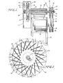
cutter 108 is more readily understood with reference to Fig. 2 wherein aframe 120 supports adouble pillow block 121 and adrive motor 122. Thedouble pillow block 121 receives aninner shaft 123 and anouter sleeve 124. Theinner shaft 123 has anoutboard rotor 125 at one end and anouter timing sheave 127 at the other end. Theouter sleeve 124 has aninboard rotor 126 mounted at one end and aninner'timing sheave 128 at the other end. - The
outer timing sheave 127 and theinner timing sheave 128 are driven by thedrive motor 122 through respective drive sheaves 129 and 130 anddrive belts belt tensioning device 100 may be provided (see Fig. 1). A plurality ofknives 133 of a suitable material are fixed to theinner rotor 126 and likewise a plurality ofknives 133 are fixed to theouter rotor 125 in a quantity which is sufficient to divide the rotor cutting circle into a suitable number of spaces with the spaces defining the desired length of cut. The knives could be arranged with random or equal spacing depending upon the type of material and the length of cut desired. Anexternal hub plate 138 is secured to theinner shaft 123 and applies adjustable pressure to therotor 125 through, aresilient pressure washer 137. - The
external hub plate 138 is also rotatably fixed both to therotor 125 and to theinner shaft 123. Thepressure washer 137 is loaded against therotor 125 by a thrust bearing 134 (provided between thesheaves 127, 128), athrust collar 135 and anadjustable locknut 136. By tightening and setting theadjustable locknut 136, it is possible to achieve any reasonable degree of "fit-up" pressure desired on the knife gap near the line 3-3 in Fig. 2. Hence, any magnitude of pressure 'on the many knife edges is possible depending upon the cutting pressure required for the particular type of fiber being cut. - It is preferable, of course, to minimize the weight of the rotors and the parts attached thereto so as to decrease the tendency of the rotors to oscillate unduly from kinetic energy of rotation. It is'preferable, however, to maintain an adequate angular momentum so as to avoid a "slip-stick" condition common to low rotational speeds of the apparatus. In this way, it has been found advantageous to confine the "fit-up" resiliency of the assembly to only one member with a resilient mounting of the knives in only one rotor adjudged to be suitable for practical balancing purposes.
- Resilient mounting within one of the
rotors press fit pin 191 provided in abore 192 extending through the knife and the rotor. The end of the press fit pin is preferably ground flush after assembly. - Air holes 178 (see Figs. 14 and 15) may be provided near the
shaft 123 at the center of either rotor to permit the rotor unit to become a centrifugal fan. These air holes would aid the centrifugal force acting on the cut fiber and tend to blow or fling the cut fiber away from the rotors and toward thechute 114. The air holes could also be provided with forced air from an external source (not shown) to further enhance the effect. If desired, acover plate 179 havingholes 180 corresponding to theholes 178 can be rotatably mounted with respect to the one rotor so as to permit a control or damping of the amount of air supplied through the air holes 178. - According to a further feature of the present invention, sizing or finish can be controllably introduced into the air (drawn or forced) through the air holes. With reference again to Figs. 14 and 15, a
channel 181 may be provided about theholes 180 on thecover plate 179. Asuitable conduit 182 would supply a metered amount of sizing or finish to the channel with the sizing or finish then supplied to the rotors through the air holes 178. The sizing or finish would enhancer the performance of the cut staple for its particular end use and would also aids in lubricating the sliding plurality of knives affixed to the rotors. - It is preferred that one of the rotors has one or more additional knives than the other rotor. If the rotors each had the same number of knives arranged in an equally spaced relationship on each of the rotors, at a certain point during the co-rotation of the rotors the outermost end of the knives on one rotor would coincide with the outermost end of the knives on the other rotor. At this time, there would be no opening into which the fiber to be cut could be fed. It is also preferred that the rotors be timed by the drive sheaves 129 and 130, the
drive belts - The plurality of
knives 133 on each rotor, shewn ing Fig. 3, are slanted so they do not point to the rotor centor and are therefore not true spokes. In this way, each of the knives is preferably arranged so that it forms an angle of other than 90° with a tangent line at the periphery of the rotor. - The
knives 133 together form a pinwheel configuration on the surface of the rotor and present a maze of crossing points. In this way, the knives of each rotor are arranged in divergent directions with respect to the adjacent knives of the other rotor so as to form the scissors-like arrangement. This is true because the knives on one rotor are slanted in a.direction opposite to those on the other rotor when assembled with their respective knives facing each other. If each rotor is viewed separately, however, looking toward the surface with the knives, the knives are preferably oriented in the same direction except that one of rotors contains at least one more knife than the other rotor. - The surfaces of all of the knives of each rotor are preferably ground in a flat plane. The slant causes any one knife on the
rotor 125 to cross three knives on therotor 126, in the illustrated embodiment of Fig. 7. Whether the knives of one rotor cross one, two, three or more knives of the other rotor depends upon the configuration (i.e. spacing, angle of orientation, thickness, etc.) of the knives of the rotors. Therefore it can be seen that with sixty knives on one rotor providing a three quarter inch cut, (see Fig. 7) the embodiment has a maze of one hundred and eighty touch points constantly sliding along the edges of the many knives to sharpen them. This sharpening action continues even while the edges of the knives are cutting fiber, because the sharpening action does not disturb the cutting edge proper. When a finish is applied to the fiber immediately prior to cutting, the finish may be designed to act as a cutting oil further enhancing the sharpening action. - With reference now to Fig. 8, the tow band is woven snake-like between the out-of-mesh knives at the twelve o'clock position. The tension of the mechanism 107 (see Fig. 1) along with the gripping of the tow band by the adjacent knives of the rotors at about the nine o'clock position, causes the tow band to be pulled down between the out-of-mesh knives. As the tow progresses around the periphery of the rotors, the knives come into closer mesh with one another until the tow is finally cut and free to be thrown off radially.
- The progressive meshing of the
knives 133 on theouter rotor 125 and theinner rotor 126 is better understood with reference to Figs. 4, 5 and 6. As stated previously, the rotors have a different number of knives, one rotor preferably having one less knife than the other and rotating at a faster rate of linear speed so as to have every knife mesh in each revolution as every knife of the faster rotor advances with respect to an adjacent knife of the slower rotor during each revolution. In Fig. 4, the knives are seen in a maximum out-of-mesh position. This point is identified as the "twelve o'clock". position (with reference to Fig. 1) and is the point where the fiber is fed into the cutter. In this position, the fiber can be pulled down between the knives serpentine-like by the tension on the tow band. - In Fig. 5, labeled the "nine o'clock" position, the knives are shown approaching mesh. The fiber bundle is being squeezed and the magnitude of pull which can be exerted on the tow bundle by the several sets of semi-meshing knives is more fully understood. In Fig. 6, labeled the "six o'clock" position, the knives are in full mesh, the faster rotor with the fewer knives having overtaken the slower rotor with more knives. Obviously the tow band, previously having zigzagged snake-like to avoid being severed, has now passed the point where the two knives have meshed firmly in a scissors-like manner and has been severed into staple of a length equivalent to the spacing between the generally spoke-like knives. Note that increasing the tow tension will force the tow band toward the hub, resulting in a slightly shorter staple and slower feed, while slackening on the tow tension will permit it to range outward along the rotors where the knives are spaced further apart resulting in a slightly longer staple and a faster feed. The orientation of the knives, coupled with a variation of the feed-on point, e.g. one or two o'clock instead of twelve o'clock, and a setting of the rotor speed will result in exact control over both tow band tension and staple length. The
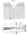
knives 133, in different stages of mesh in motion on therotors - The advancement of a knife of one rotor with respect to a knife of the other rotor may be seen more readily with reference to the panoramic view of Fig. 10. As shown, at the twelve o'clock position the knives are in maximum mis-mesh. Moving from right to left in the drawing (at a radial position just beyond the tow band 106) the knives are seen to come progressively into cutting engagement with one another until maximum mesh is achieved at the six o'clock position. At this point, the already cut tow band is flung radially outwardly. Moving further to the left (about the rotors) the knives progressively again assume the maximum mis-mesh position at twelve o'clock.
- The view of Fig. 10 can also be considered as illustrating the progressive movement of a single knife of one rotor toward and then beyond an adjacent knife of the other rotor. In this way, the one knife may be seen to advance with respect to the other knife of the other rotor during the relative rotation of the rotors. The view of Fig. 10 can be considered to show the relative movement of individual knives of the rotors with respect to one another much as a properly adjusted strobe light and camera arrangement shows the relative positions of the knives moving relative to one another about the rotors during rotation.
- With reference to Fig. 11, the relative movement of the knives of one rotor with respect to the knives of the other. rotor is illustrated in a manner similar to that of Fig. 10 but with an axial view rather than a radial view. In Fig. 11, the curved periphery of the rotors has been illustrated in a linear view. Moving from right to left, the outer ends of the knives are directed upwardly and slant away from one another to provide the "V" groove entrance (see also Fig. 8). At the twelve o'clock position, the radially outermost flat portions of the knives of the rotors are in maximum mis-mesh. Progressing to the six o'clock position, the radially outermost flat portions of the knives first engage one another to prevent the tow band from escaping between the knives and subsequently cut the tow band (at least by the six o'clock position). The cut tow band segments are then free to fly radially outwardly from the rotors.
- Referring to the embodiment of Fig. 3, the scissors-like cutting of the tow is understood to proceed continuously as the two rotors mesh. Fig. 3 is taken along the section 3-3 in Fig. 2 which cuts through one set of knives looking into the other set. The angles of the knives and their scissors-like shear arrangement become clear when this assembly is analyzed especially with reference to Figs. 10 and 11. It will be noted that neither set of knives is arranged so that the knives will pass through the center or hub of the rotor. Therefore, they are not true spokes.
- Instead, the knives of each rotor are tangential with respect to an imaginary circle concentric about the axis of the rotor with the radius of the imaginary circle depending upon the angle of inclination of the knives. The angles have been designed to give the two sets of knives a scissors-like shearing effect at their ideal cutting point. Development work, in an attempt to determine the optimum parameters for general use, points to knives set at an angle of 15° to a radial line, making a total scissor angle of 30° between the two knives at peripheral contact. It is to be understood that this angle will vary gradually as the rotors turn. Furthermore, knives set in the rotor at 10° to the planar surface and sharpened with a 10° rake angle also appear near the optimum for general use.
- The shape of the rotors and the knives preferably cooperate with one another to form a "V" groove as best seen in Fig. 9. Each of the
knives 133 is preferably provided with an angularlysloping section 160 at the outer end of the knife. Thesesections 160 s'lope toward the periphery of therotors knives 133 have a radius section or knee 161 which forms an obliquely curved bottom to the "V". Theangular slopes 160 and the radii 161 on the knives are designed especially to cooperate to collect any straying filaments and direct them into the rounded crevice of the "V" groove in zigzag fashion where the filaments are urged further between the sets of rotating knives ready for severing. - Referring to Fig. 12, a second embodiment of a cutter according to the present invention is illustrated. In this embodiment only a
single rotor 126 contains a plurality ofknives 133 which mesh with a suitable wear-resistant surface 141, on arotor 140. Thesurface 141 is pressed against theknives 133 of thecompanion rotor 126 by aresilient device 142 to insure contact in the cutting zone. Therotor 126 is mounted, as in the'previous arrangement, on asleeve 124 which carries ashaft 123 that mounts arotor 140. Athrust bearing 144 is aligned by ahub 145 mounted on awobble shaft 146. Thewobble shaft 146 is actuated by a force (the arrow 147) from an externalstationary source 148 to provide suitable cutting pressure between theknives 133 and the wearresistant surface 141. Thewobble shaft 146 also provides anopening niche 143 into which the tow band can enter. - The embodiment of Fig. 12 is especially adapted to cut glass fiber or materials which fracture or readily scuff apart. The timing of the rotors would not be as critical in this embodiment since the knives would set down on the fiber, grip it firmly, and then scrape-along the companion rotor surface under pressure until the tow band has severed. The knives on such a modification would obviously be very hard and the companion rotor surface would be a hardened metal or other suitable material as well. The wear surface would be expected to erode and would therefore be expendable. Also, the knives would require sharpening occasionally.
- The previous embodiments show cutting units which accept the tow band from outside the periphery of the rotors, grip it, cut it and discharge it again toward the outside. Fig. 13 illustrates a further embodiment of the present invention wherein
fibrous tow bands 153 are fed intohollows 154 in alignedmount shafts 149 from opposite ends of a machine, progressing thence to be cut and discharged, as previously explained, on the rotor periphery. This machine can be described as an "inside out" cutter. Referring to Figure 13,shafts 149, mounted in aligningbearings 150, cooperate withdrive rotors 151 which carry embeddedknives 152. Therotors 151 are drivably timed, by an apparatus similar to that in Fig. 2, to mesh at least once per revolution.Fibrous tow bands 153 enter through thehollows 154 of theshafts 149 and proceed through right angle turns at 155 to an internalsloping knife channel 156. The tow band lies, by centrifugal force, in a circular band zigzagging betweenknives 152 until rotation of therotors 151 and subsequent meshing of theknives 152 cause thetows 153 to be severed. The cut fiber exits at the periphery of therotors 151 through the spacedknives 152 ascut staple 157 and is carried away by a collector chute (not shown). - Of course, it is possible to provide apparatus according to the present invention having a pair of rotors mounted off axis with respect to one another or with the knives mounted on members other than rotors. It is preferable, however, that the knives be arranged for travel in one or more continuous paths, (for example, on one or more endless belts) so that the knives of the one member are arranged in sliding contact with either a smooth surface or a plurality of knives of the other member. Preferably the two members are moving in the same direction at the point of sliding contact but at slightly different speeds so as to cut the material between the members.
- It is preferred that two of the instant machines of Fig. 1 work in tandem with one of the machines acting as a spare. In this manner, a first machine (#1) would be taken out of service for repairs or maintenance while a second machine (#2) is substituted. A simple threadup method is afforded by the machines wherein the new machine is placed upstream of the machine in use (in line with the tow band). The new machine (#2) is turned'on and synchronized in feed speed with the operating machine (#1). Now the tow band is pressed gently through the opening in the rotor housing of machine (#2) into the "V" groove niche formed by the rotors and knives where it is grabbed by the action of the knives on the tow band sides. This action takes the tow band from the downstream machine and the cutting process on the new machine begins. The old machine is then removed for repairs. The new machine may be moved on a track or other device to the position of the old machine. The old machine, when repaired, is inserted back into the line to occupy the role. of a new machine waiting to be used. In this manner, no spinning line ever need be shut down for cutter repairs.
- Upon initial thread-up of the cutter of the present invention, a number of adjustments need to be checked. The output conveyor (belt or air) needs to be adjustable to be used by both machines (e.g., #1 and #2). The length of the output staple needs to be checked and the speed of the cutter set with both the line speed and the tow band tension to procure the exact cut length desired. The knife pressure needs to be determined either by motor line draw versus tow size and tension or by a micrometer adjustment on the knife
pressure adjustment locknut 136. An air cylinder or diaphragm provided with a pressure regulator, all equipment well known in the art, can be installed to monitor the knife pressure at all times after it is initially determined. Knife pressures obviously vary with changes in the generic type of fiber being cut, the desired staple length, the tow band size, and the knife material and condition. - The tow band can now be fed into the cutter at linear speeds of 20,000 feet per minute and up. The tow band is clamped by knives crossing over each other along its feed-in path on the rotor circle. The tow band follows this path only shortly, for example, from the topmost or twelve c'clock point to near the bottommost or six o'clock point, until the timed rotors catch the tow in a squeeze between two knives. The tow is then severed and flung outward by centrifugal force. Both rotors are dynamically balanced and are running in the same direction with one rotor running only slightly faster than the other. Of course, the rotors are rotating at particular angular velocities but these angular velocities produce separate linear speeds at the periphery of the rotors depending upon the diameter of the rotors. For example, using fifteen inch diameter rotors at a fiber tow feed rate of 20,000 feet per minute, cutting three quarter inch staple, one rotor may preferably be running at 5093 rpm, the other rotor preferably running at 5178 rpm with the machine making about 320,000 cuts per minute.
- In summary, during operation of one preferred embodiment apparatus according to the present invention, a tow band or other funicular material is fed between a first and a second series of knives at a point of mis-mesh of the knives. The two sets of knives are moving in the same general direction with one set preferably moving at a faster linear speed than the other set so that the. knives of one set advance with respect to the other set. In this way, the tow band is first grasped between the sets of advancing knives and then cut into individual segments by the sliding relative movement of the knives.
- Four valuable advantages may be seen in the present invention. First,.-the knives are angled in such a manner that they trap the tow band very soon after it is introduced snake-like between the rotors and will not let centrifugal force induce the tow to escape. It is as if the scissors were outside the rim cutting toward the hub. Accordingly, the tow cannot escape being cut and is trapped and held until cutting occurs.
- Second, the arrangement of the knives insures that any knife will always be touching at least two other knives. Hence, there is no fulcrum or seesaw loading or vibration tending to destroy the rotor or its components. In the preferred embodiment, most of the knives will be bearing on three other knives and a fifteen inch rotor cutting three quarter inch staple will provide over three square.inches of hardened knife surface constantly in bearing contact.
- Third, since the knives do not just touch momentarily, as in the age old knife-bedplate relationship, but slide along the other knives, a filing motion occurs and the knives self sharpen in a manner that is similar to the method a butcher uses to sharpen his knives. Because of the sharpening action the rotors can be run for a period of time required to wear down over one eighth inch depth on all the knives in both rotors. On the aforementioned fifteen inch rotor cutting three quarter inch staple, this would entail the wearing away of over eight cubic inches of hardened metal from a single set of knives. Considering the self-sharpening feature, this could very well mean periods of non-stop running of a year or more.
- Fourth, the knife angle and configuration in both rotors is so arranged that at the time the tow band is cut, the knives are spaced apart at their maximum distance thus facilitating the exit of the cut staple from the rotor assembly. Additionally, the centrifugal force has now achieved its maximum, and the output of the cutter can thus be directed toward a given point for discharge, not unlike the pointing of a hose nozzle.
- It is to be understood that there are variations in the apparatus or method to accomplish the same results as outlined in the preferred embodiments, the specification and the explanations given above. Some immediate variations which are feasible include gears to time the rotors; a cutter built in a hollow shaft, variable speed motor thus eliminating the separate journal box; solid carbide; carbide tipped, or other exotic hardened knives; a reverse blower system to force cut staple inboard of the rotors and thence outwardly through the hollow shafts; and many others. Furthermore, the knives may be arranged on other than concentrically mounted rotors and may even be arranged for example on endless belts so as to travel in continuous paths with respect to one another being in sliding contact only a portion of the time.
Claims (24)
Applications Claiming Priority (2)
| Application Number | Priority Date | Filing Date | Title |
|---|---|---|---|
| US78195 | 1979-09-24 | ||
| US06/078,195 US4445408A (en) | 1979-09-24 | 1979-09-24 | Method and apparatus for cutting continuous fibrous material |
Publications (3)
| Publication Number | Publication Date |
|---|---|
| EP0026107A2 true EP0026107A2 (en) | 1981-04-01 |
| EP0026107A3 EP0026107A3 (en) | 1981-09-09 |
| EP0026107B1 EP0026107B1 (en) | 1986-05-21 |
Family
ID=22142533
Family Applications (1)
| Application Number | Title | Priority Date | Filing Date |
|---|---|---|---|
| EP80303349A Expired EP0026107B1 (en) | 1979-09-24 | 1980-09-24 | Method and apparatus for cutting continuous fibrous material |
Country Status (5)
| Country | Link |
|---|---|
| US (1) | US4445408A (en) |
| EP (1) | EP0026107B1 (en) |
| JP (1) | JPS5653211A (en) |
| CA (1) | CA1139656A (en) |
| DE (1) | DE3071611D1 (en) |
Families Citing this family (10)
| Publication number | Priority date | Publication date | Assignee | Title |
|---|---|---|---|---|
| JPS6047423A (en) * | 1983-08-25 | 1985-03-14 | Nippon Telegr & Teleph Corp <Ntt> | Method for pattern formation |
| DE3506282A1 (en) * | 1985-02-22 | 1986-08-28 | Lentia GmbH Chem. u. pharm. Erzeugnisse - Industriebedarf, 8000 München | DEVICE FOR CUTTING RIBBON OR STRANDED GOODS |
| US4873537A (en) * | 1985-06-08 | 1989-10-10 | Canon Kabushiki Kaisha | Image recording apparatus for producing a plurality of pulse width modulated signals on the basis of image data |
| JP2906590B2 (en) * | 1990-06-14 | 1999-06-21 | 三菱瓦斯化学株式会社 | Surface treatment agent for aluminum wiring semiconductor substrate |
| JPH05263322A (en) * | 1991-01-28 | 1993-10-12 | Nishikawa Roozu Kk | Method for cutting yarn and device therefor |
| KR100419994B1 (en) * | 1994-12-26 | 2004-04-21 | 가부시끼가이샤.다께하라기까이겡규쇼 | Fiber cutting apparatus |
| US5894773A (en) * | 1996-08-30 | 1999-04-20 | Owens Corning Fiberglas Technology, Inc. | System for forming and cutting a mineral fiber tow |
| US7004053B1 (en) * | 2000-03-15 | 2006-02-28 | Kimberly-Clark Worldwide, Inc. | System for measuring and controlling cut length of discrete components in a high-speed process |
| US7588438B2 (en) * | 2005-11-01 | 2009-09-15 | The Board Of Regents, The University Of Texas System | System, method and apparatus for fiber sample preparation for image analysis |
| ES2452022T3 (en) * | 2006-02-06 | 2014-03-31 | Abb Research Ltd. | Press line system and method |
Citations (2)
| Publication number | Priority date | Publication date | Assignee | Title |
|---|---|---|---|---|
| DE674207C (en) * | 1936-05-03 | 1939-04-06 | Zellwolle Arbeitsgemeinschaft | Device for cutting endless artificial fiber slivers |
| FR1433162A (en) * | 1965-05-12 | 1966-03-25 | Elitex Zavody Textilniho | Fiber-cutting feed mechanism for carding machines and a machine provided with said device or the like |
Family Cites Families (14)
| Publication number | Priority date | Publication date | Assignee | Title |
|---|---|---|---|---|
| US1510729A (en) * | 1923-04-26 | 1924-10-07 | Weisner Charles Emmett | Cutting mechanism for cigarette machines |
| US2214707A (en) * | 1936-09-24 | 1940-09-10 | Bauer Bros Co | Sealing ring for grinders |
| US2221022A (en) * | 1939-10-18 | 1940-11-12 | Eastman Kodak Co | Rotary staple cutting machine |
| DE748315C (en) * | 1939-10-23 | 1944-11-01 | Device for cutting endless artificial thread strips or long-fiber spun material | |
| US2278662A (en) * | 1941-08-22 | 1942-04-07 | American Viscose Corp | Device for cutting filamentary material |
| US2391719A (en) * | 1944-07-27 | 1945-12-25 | Du Pont | Apparatus for cutting filaments |
| US2642135A (en) * | 1946-03-05 | 1953-06-16 | Regalia Gian Carlo | Cutting machine for synthetic silk and rayon yarns |
| US2745491A (en) * | 1952-05-16 | 1956-05-15 | Owens Corning Fiberglass Corp | Apparatus for the preparation of glass fiber reinforced molding compositions |
| US3111875A (en) * | 1956-02-07 | 1963-11-26 | Takehara Kokuji | Fiber cutting device |
| US3451630A (en) * | 1964-04-28 | 1969-06-24 | Jarmil Pav | Beating device for the continuous processing of material stock |
| US3238828A (en) * | 1964-05-28 | 1966-03-08 | Du Pont | Yarn cutter |
| GB1252127A (en) * | 1967-11-22 | 1971-11-03 | ||
| US3978751A (en) * | 1974-10-09 | 1976-09-07 | Farmer Earl T | Apparatus for cutting fibrous tow into staple |
| DE2714962C3 (en) * | 1977-04-04 | 1981-05-07 | Karl-Heinz 3100 Celle Stukenberg | Method and device for the removal and shredding of edge strips |
-
1979
- 1979-09-24 US US06/078,195 patent/US4445408A/en not_active Expired - Lifetime
-
1980
- 1980-09-16 CA CA000360278A patent/CA1139656A/en not_active Expired
- 1980-09-24 EP EP80303349A patent/EP0026107B1/en not_active Expired
- 1980-09-24 JP JP13179280A patent/JPS5653211A/en active Granted
- 1980-09-24 DE DE8080303349T patent/DE3071611D1/en not_active Expired
Patent Citations (2)
| Publication number | Priority date | Publication date | Assignee | Title |
|---|---|---|---|---|
| DE674207C (en) * | 1936-05-03 | 1939-04-06 | Zellwolle Arbeitsgemeinschaft | Device for cutting endless artificial fiber slivers |
| FR1433162A (en) * | 1965-05-12 | 1966-03-25 | Elitex Zavody Textilniho | Fiber-cutting feed mechanism for carding machines and a machine provided with said device or the like |
Also Published As
| Publication number | Publication date |
|---|---|
| JPS5653211A (en) | 1981-05-12 |
| JPS6225767B2 (en) | 1987-06-04 |
| DE3071611D1 (en) | 1986-06-26 |
| CA1139656A (en) | 1983-01-18 |
| US4445408A (en) | 1984-05-01 |
| EP0026107B1 (en) | 1986-05-21 |
| EP0026107A3 (en) | 1981-09-09 |
Similar Documents
| Publication | Publication Date | Title |
|---|---|---|
| US3508461A (en) | Chopper for glass strands | |
| US3815461A (en) | Apparatus for chopping strand | |
| US3869268A (en) | Method and apparatus for chopping fibers | |
| US4445408A (en) | Method and apparatus for cutting continuous fibrous material | |
| US4637286A (en) | Staple cutting for fiber reinforcement material | |
| JPS6127488B2 (en) | ||
| US7832315B2 (en) | Fiber chopper apparatus and method | |
| IL158391A (en) | Needling loom feeding with continuous helical strip | |
| US4014231A (en) | Method and apparatus for cutting tow | |
| US6148640A (en) | Method for making chopped fiber | |
| US4347071A (en) | Apparatus for production and cutting of glass fibres | |
| FI103821B (en) | Opposite directions rotating tear strip knives | |
| US4120222A (en) | Staple length cutter with low noise level jet to assist in doffing cut staple | |
| US4345355A (en) | Process and apparatus for cutting a tow and continuously opening the fibers obtained | |
| US4300422A (en) | Apparatus for cutting filamentary material | |
| US4141115A (en) | Method and apparatus for cutting textile tow into staple | |
| US3942401A (en) | Method for cutting fibers | |
| US4660777A (en) | Apparatus for manufacturing flakes | |
| US4263790A (en) | Method for knitting and severing synthetic pile loop fabrics | |
| US3831473A (en) | Device for cutting endless material, for example for the production of staples from synthetic fibers | |
| US4083276A (en) | Method for cutting tow | |
| US4367084A (en) | Threading means for strand pulling and chopping apparatus | |
| US5926918A (en) | Apparatus and method for opening and for reclaiming fibers | |
| US3962966A (en) | Chip crusher | |
| US5003855A (en) | Chopper with auto feed |
Legal Events
| Date | Code | Title | Description |
|---|---|---|---|
| PUAI | Public reference made under article 153(3) epc to a published international application that has entered the european phase |
Free format text: ORIGINAL CODE: 0009012 |
|
| AK | Designated contracting states |
Designated state(s): BE DE FR GB IT NL SE |
|
| PUAL | Search report despatched |
Free format text: ORIGINAL CODE: 0009013 |
|
| AK | Designated contracting states |
Designated state(s): BE DE FR GB IT NL SE |
|
| 17P | Request for examination filed |
Effective date: 19810925 |
|
| 19U | Interruption of proceedings before grant |
Effective date: 19831129 |
|
| 19W | Proceedings resumed before grant after interruption of proceedings |
Effective date: 19860213 |
|
| GRAA | (expected) grant |
Free format text: ORIGINAL CODE: 0009210 |
|
| RAP1 | Party data changed (applicant data changed or rights of an application transferred) |
Owner name: MINIFIBERS, INC. |
|
| AK | Designated contracting states |
Kind code of ref document: B1 Designated state(s): BE DE FR GB IT NL SE |
|
| REF | Corresponds to: |
Ref document number: 3071611 Country of ref document: DE Date of ref document: 19860626 |
|
| ET | Fr: translation filed | ||
| ITF | It: translation for a ep patent filed | ||
| RAP2 | Party data changed (patent owner data changed or rights of a patent transferred) |
Owner name: MINIFIBERS, INC. |
|
| PLBE | No opposition filed within time limit |
Free format text: ORIGINAL CODE: 0009261 |
|
| STAA | Information on the status of an ep patent application or granted ep patent |
Free format text: STATUS: NO OPPOSITION FILED WITHIN TIME LIMIT |
|
| 26N | No opposition filed | ||
| ITTA | It: last paid annual fee | ||
| EAL | Se: european patent in force in sweden |
Ref document number: 80303349.7 |
|
| PGFP | Annual fee paid to national office [announced via postgrant information from national office to epo] |
Ref country code: SE Payment date: 19980904 Year of fee payment: 19 |
|
| PGFP | Annual fee paid to national office [announced via postgrant information from national office to epo] |
Ref country code: FR Payment date: 19980909 Year of fee payment: 19 |
|
| PGFP | Annual fee paid to national office [announced via postgrant information from national office to epo] |
Ref country code: GB Payment date: 19980917 Year of fee payment: 19 |
|
| PGFP | Annual fee paid to national office [announced via postgrant information from national office to epo] |
Ref country code: NL Payment date: 19980929 Year of fee payment: 19 |
|
| PGFP | Annual fee paid to national office [announced via postgrant information from national office to epo] |
Ref country code: DE Payment date: 19981005 Year of fee payment: 19 |
|
| PGFP | Annual fee paid to national office [announced via postgrant information from national office to epo] |
Ref country code: BE Payment date: 19981118 Year of fee payment: 19 |
|
| PG25 | Lapsed in a contracting state [announced via postgrant information from national office to epo] |
Ref country code: GB Free format text: LAPSE BECAUSE OF NON-PAYMENT OF DUE FEES Effective date: 19990924 |
|
| PG25 | Lapsed in a contracting state [announced via postgrant information from national office to epo] |
Ref country code: SE Free format text: THE PATENT HAS BEEN ANNULLED BY A DECISION OF A NATIONAL AUTHORITY Effective date: 19990929 |
|
| PG25 | Lapsed in a contracting state [announced via postgrant information from national office to epo] |
Ref country code: BE Free format text: LAPSE BECAUSE OF NON-PAYMENT OF DUE FEES Effective date: 19990930 |
|
| BERE | Be: lapsed |
Owner name: MINIFIBERS INC. Effective date: 19990930 |
|
| PG25 | Lapsed in a contracting state [announced via postgrant information from national office to epo] |
Ref country code: NL Free format text: LAPSE BECAUSE OF NON-PAYMENT OF DUE FEES Effective date: 20000401 |
|
| EUG | Se: european patent has lapsed |
Ref document number: 80303349.7 |
|
| GBPC | Gb: european patent ceased through non-payment of renewal fee |
Effective date: 19990924 |
|
| PG25 | Lapsed in a contracting state [announced via postgrant information from national office to epo] |
Ref country code: FR Free format text: LAPSE BECAUSE OF NON-PAYMENT OF DUE FEES Effective date: 20000531 |
|
| NLV4 | Nl: lapsed or anulled due to non-payment of the annual fee |
Effective date: 20000401 |
|
| PG25 | Lapsed in a contracting state [announced via postgrant information from national office to epo] |
Ref country code: DE Free format text: LAPSE BECAUSE OF NON-PAYMENT OF DUE FEES Effective date: 20000701 |
|
| REG | Reference to a national code |
Ref country code: FR Ref legal event code: ST |