EP0025929A1 - Method for bending a metal pipe - Google Patents
Method for bending a metal pipe Download PDFInfo
- Publication number
- EP0025929A1 EP0025929A1 EP80105363A EP80105363A EP0025929A1 EP 0025929 A1 EP0025929 A1 EP 0025929A1 EP 80105363 A EP80105363 A EP 80105363A EP 80105363 A EP80105363 A EP 80105363A EP 0025929 A1 EP0025929 A1 EP 0025929A1
- Authority
- EP
- European Patent Office
- Prior art keywords
- bending
- pipe
- radius
- constant
- heater
- Prior art date
- Legal status (The legal status is an assumption and is not a legal conclusion. Google has not performed a legal analysis and makes no representation as to the accuracy of the status listed.)
- Granted
Links
Images


Classifications
-
- B—PERFORMING OPERATIONS; TRANSPORTING
- B21—MECHANICAL METAL-WORKING WITHOUT ESSENTIALLY REMOVING MATERIAL; PUNCHING METAL
- B21D—WORKING OR PROCESSING OF SHEET METAL OR METAL TUBES, RODS OR PROFILES WITHOUT ESSENTIALLY REMOVING MATERIAL; PUNCHING METAL
- B21D7/00—Bending rods, profiles, or tubes
- B21D7/02—Bending rods, profiles, or tubes over a stationary forming member; by use of a swinging forming member or abutment
- B21D7/024—Bending rods, profiles, or tubes over a stationary forming member; by use of a swinging forming member or abutment by a swinging forming member
- B21D7/025—Bending rods, profiles, or tubes over a stationary forming member; by use of a swinging forming member or abutment by a swinging forming member and pulling or pushing the ends of the work
-
- B—PERFORMING OPERATIONS; TRANSPORTING
- B21—MECHANICAL METAL-WORKING WITHOUT ESSENTIALLY REMOVING MATERIAL; PUNCHING METAL
- B21D—WORKING OR PROCESSING OF SHEET METAL OR METAL TUBES, RODS OR PROFILES WITHOUT ESSENTIALLY REMOVING MATERIAL; PUNCHING METAL
- B21D7/00—Bending rods, profiles, or tubes
- B21D7/16—Auxiliary equipment, e.g. for heating or cooling of bends
- B21D7/162—Heating equipment
Definitions
- This invention relates to the method for hot bending a metal pipe, and especially to keep heating temperature substantially constant while gradation bending, in which curvature is changed gradually at the start and the end of bending, is operated in order to make change of pipe wall thickness very gentle and to produce smooth bends.
- a method for hot bending a metal pipe wherein the pipe is heated locally with a circular heater such as induction heater or the like, and the heated zone is moved relatively to the pipe by means of moving the pipe and/or the heater while bending moment is applied to said heated zone to cause bending, and after which it is cooled at the vicinity of it, is already known publically.
- a circular heater such as induction heater or the like
- Above invention is based on basic principle of hot bending and then covers many cases, where in, a pipe to be bent is heated locally with a circular heater such as induction heater or the like and the heated zone is moved relatively to the pipe by means of moving the pipe to be bent and/or the heater relatively to the pipe in a longitudinal direction of the pipe to be bent while bending moment is applied to the heated zone to cause bending, and after which it is cooled at the vicinity of it, and further, bending is started at a larger radius than that specified and changed smaller gradually untill it becomes slightly smaller than specified radius within a certain predetermined small range of bending angle, and at the end of bending it is changed larger gradually again within a certain predetermined small range of bending angle.
- a circular heater such as induction heater or the like
- Fig. 1 1 is a pipe to be bent
- 2 is bent portion of the pipe
- 3 is the center of heated zone where deformation of bending arises
- H is a heating mean (such as induction heater) equipped with cooling mean in one body
- 4 is a bending arm which clamps pipe 1 at the top of it and can rotate freely around a center
- 5 6 is guide rollers to guide and and support pipe 1 against bending forces
- P is thrust to feed pipe 1 and exert bending moment at the heated zone 3
- W is speed of work pipe 1 to the right
- h speed of heater H to the left.
- A is a point which is an intersection of the axis of pipe 1 and a plane which is virtical to pipe 1 and includes the point 0 .
- heater H In normal bending, heater H is located at point A or at the vicinity of it and then radius of bending is kept substantially equal to the effective length Ro of bending arm 4.
- gradation bending heater H is at first located at point 3 of Fig. 1 which is apart from A by certain proper distance towards bending arm 4 and is displaced gradually to point A in order to operate gradation bending in which radius of bending is changed from large to small gradually.
- This invention relates to above two cases to keep heating temperature constant while gradation bending is operated. It is clear that a very large heating capacity is required in order to cover large change of heating power in case-1, and then case-2 where heating power is kept constant is much more preferable than case-1. But case-1 may be useful when capacity of heating power is large enough because of simpleness of control mechanism that is only changing effective power supply corresponding to the change of relative speed of heated zone to the pipe to be bent.
- radius R is again changed gradually from Ro to normally 2Ro in above case by means of changing speed h from 0 to W gradually and changing speed V from W to 2W.
- gradation starts at point ⁇ 2 and programmed angle y must be counted from ⁇ 2, being 0 at ⁇ 2 and 8 at a' where bending is completed.
- gradation range B should be not larger than required minimum value and preferably should be less than 8 degree. Because too large gradation range should be compensated with too small radius of bending between the start and the end gradation in order to give mean radius of bending equal to specified radius Rs. More preferably 5 to 6 degree of gradation range is adopted, because in such small gradation we can make deviation of bending radius negligible small. If very large range of gradation should be adopted, it would cause mechanical hard problems and would cause some bad effects for preciseness of bending radius.
- Above program control may be treated with a micro computer, electric instruments and electric motors or hydraulic equipments.
- Fig. 4 elements which are common with Fig. 1 are nominated with the same figure, and further 7 is a thrusting mean to clamp the tail end of pipe 1 and to feed pipe 1 with thrusting force P, 8 is a driving mean to drive thrusting mean 7, 9 is a screw which is installed between the thrusting mean 7 and heater H in order to give constant relative speed V, 10 is a nut to move the screw 9 being supported with a bracket 11 and rotated at a proper constant speed with a geared variable speed motor 12. Bracket 11 is fixed on the thrusting mean 7 and heater H is displaceable on rail parallel to pipe 1.
- roller 5' is installed at the opposite side of roller 5 near point 0.
- Roller 5' is used for controlling excess enlargement of bending radius R caused by misoperation or some other effects, but roller 5' may be omitted if some other control mechanism to regulate R is equipped.
- gradation range e had better be taken smaller than 8 degree and preferably should be 5 or 6 degree is not to cause excess deviation of radius R from Ro and to minimize excess reaction force at the pivot 0 and other parts of the bending machine and at the same time to perform precise bending.
- a method would be adopted in which auxiliary feed back temperature control system including to measure heating temperature is equipped in order to get heating temperature more precisely constant, but it is effective only when speed V is very small.
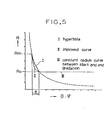
- Fig. 5 shows another program which is a little bit improved than the case based on hyperbola (Fig. 2). Because at the early stage of gradation R- ⁇ curve may be taken much more steep than hyperbola and at the end of gradation the curve had better be taken more gentle than hyperbola. Such improved curve is more natural in regard to connection with constant radius curve III and makes the start of bending easier especially when Rs/D is very small.
- Fig. 1 is a diagram showing construction of typical induction pipe bender
- Fig. 2 is a diagram which shows change of radius of bending corresponding to bending angle
- Fig. 3 is a diagram which shows change of speed of pipe and heater corresponding to bending angle
- Fig. 4 is a plan of another example according to this invention
- Fig. 5 is an example showing an improved R- ⁇ program.
Landscapes
- Engineering & Computer Science (AREA)
- Mechanical Engineering (AREA)
- Bending Of Plates, Rods, And Pipes (AREA)
Abstract
Description
- This invention relates to the method for hot bending a metal pipe, and especially to keep heating temperature substantially constant while gradation bending, in which curvature is changed gradually at the start and the end of bending, is operated in order to make change of pipe wall thickness very gentle and to produce smooth bends.
- A method for hot bending a metal pipe, wherein the pipe is heated locally with a circular heater such as induction heater or the like, and the heated zone is moved relatively to the pipe by means of moving the pipe and/or the heater while bending moment is applied to said heated zone to cause bending, and after which it is cooled at the vicinity of it, is already known publically.
- But it is not well known how to prevent steep change of pipe wall thickness due to steep change of radius of curvature at the start and the end of bending when relative bending radius (ratio of bending radius to pipe diameter R/D) is very small. But it is very important to prevent such steep change of pipe wall thickness because it often causes some problems that make the bending itself very hard for instance swelling or wrinkling at the start of bending, and further even when bending is possible the steep change of pipe wall thickness causes severe concentration of bending stress.
- In relation to the method to make said change of pipe wall thickness gentle and smooth, a Japanese Patent Application 51-150809, in which bending radius is changed gradually at the start and the end of bending and besides the mean radius of bending is made equal to desired radius, is laid open and the such is called gradation bending.
- Above invention is based on basic principle of hot bending and then covers many cases, where in, a pipe to be bent is heated locally with a circular heater such as induction heater or the like and the heated zone is moved relatively to the pipe by means of moving the pipe to be bent and/or the heater relatively to the pipe in a longitudinal direction of the pipe to be bent while bending moment is applied to the heated zone to cause bending, and after which it is cooled at the vicinity of it, and further, bending is started at a larger radius than that specified and changed smaller gradually untill it becomes slightly smaller than specified radius within a certain predetermined small range of bending angle, and at the end of bending it is changed larger gradually again within a certain predetermined small range of bending angle.
- But we found that there is such a case in which heating temperature changes remarkably when relative speed of said heated zone to the pipe to be bent changes remarkably. Such change can happen in the case of typical induction bender shown by Fig. 1 where
pipe 1 is fed at a constant speed and heater H is displaced gradually for gradation. - In Fig. 1, 1 is a pipe to be bent, 2 is bent portion of the pipe, 3 is the center of heated zone where deformation of bending arises, H is a heating mean (such as induction heater) equipped with cooling mean in one body, 4 is a bending arm which clamps
pipe 1 at the top of it and can rotate freely around acenter pipe 1 against bending forces, P is thrust to feedpipe 1 and exert bending moment at theheated zone 3, W is speed ofwork pipe 1 to the right and h is speed of heater H to the left. - Further A is a point which is an intersection of the axis of
pipe 1 and a plane which is virtical to pipe 1 and includes the point 0. - In normal bending, heater H is located at point A or at the vicinity of it and then radius of bending is kept substantially equal to the effective length Ro of
bending arm 4. - In the case of gradation bending heater H is at first located at
point 3 of Fig. 1 which is apart from A by certain proper distance towards bendingarm 4 and is displaced gradually to point A in order to operate gradation bending in which radius of bending is changed from large to small gradually. - Now, change of bending radius R is operated as follows:
- Within a minute interval of
time 4t work 1 is fed right by a minute length ΔS, at a constant speed W, while heater H is moved left by a minute length ΔS2 and it is bent by a minute angle Δθ where length of pipe before and after bending is assumed unchanged and then,


- It is normal to control heating temperature by means of controlling heating power corresponding to a deviation of heating temperature measured with an instrument, but such feed back method cannot follow up well when the change of h (or V) is very large.
- We confirmed that program control of heating power supply is useful enough to keep heating temperature substantially constant for the first step (case-1), and that for the second step to keep said relative speed V(=W+h) constant from the start to the end of bending by means of controlling W and h separately according to certain program while keeping effective heating power constant is more useful.
- This invention relates to above two cases to keep heating temperature constant while gradation bending is operated. It is clear that a very large heating capacity is required in order to cover large change of heating power in case-1, and then case-2 where heating power is kept constant is much more preferable than case-1. But case-1 may be useful when capacity of heating power is large enough because of simpleness of control mechanism that is only changing effective power supply corresponding to the change of relative speed of heated zone to the pipe to be bent.
- In case-1 change of radius of bending is operated as follows:
- For example let Rs be specified radius of bending, D be pipe diameter to be bent and let Rs/D=1.5, and then at the start of bending, speed h of heater H to the left (Fig. 1) is taken equal to W (constant during bending) and changed to 0 gradually within a certain small range of bending angles and thus, changeing speed V from 2W to W, radius of curvature is changed from 2Ro to Ro gradually.
- It is true theoretically that Ro should be a little bit smaller than specified radius Rs in order to make mean radius of the bend equal to Rs, but practically difference between Rs and Ro is so small as to be covered within allowable deflection of a bending machine normally.
- At the end of bending, radius R is again changed gradually from Ro to normally 2Ro in above case by means of changing speed h from 0 to W gradually and changing speed V from W to 2W.
- In case-2, it is important how to make program to change W and h separately so as to keep V constant and to change radius of bending according to predetermined program.
- The principle would be explained with a simple example in which radius of bending is changed hyperbolically corresponding to bending angle as shown in Fig. 2, where virtical and horizontal coordinates are bending radius R and angle 0 separately.
- In case-2 and Fig. 1, 2, 3,


- Bending angle y must be counted zero at point a' in programming W and h in relation to bending angle ϕ at the start of bending, and gradation is operated from ϕ=0 to ϕ=θ (normally less than 8 degree) and finished at point θ1.
- At the end of bending, it is convenient to take another symmetrical coordinate as shown in Fig. 2 wherein original point of horizontal coordinate is 0', where bending is finished at the point a, and e is range of gradation (less than 8 degree)
- In programming, gradation starts at point θ2 and programmed angle y must be counted from θ2, being 0 at θ2 and 8 at a' where bending is completed.
- At this stage, the program should be naturally


- As the result of gradation bending accrding to program (7) and (8) speed V which is equal to W+h is kept constant and then heating temperature is kept constant only by keeping heating power constant, while W and h is changed as shown in Fig. 3 and then radius of bending is changed as shown in Fig. 2.
- It must be noted that gradation range B should be not larger than required minimum value and preferably should be less than 8 degree. Because too large gradation range should be compensated with too small radius of bending between the start and the end gradation in order to give mean radius of bending equal to specified radius Rs. More preferably 5 to 6 degree of gradation range is adopted, because in such small gradation we can make deviation of bending radius negligible small. If very large range of gradation should be adopted, it would cause mechanical hard problems and would cause some bad effects for preciseness of bending radius.
- Above program control may be treated with a micro computer, electric instruments and electric motors or hydraulic equipments.
- On the other hand there is a simple mechanical method to keep V constant for instance as shown in Fig. 4.
- In Fig. 4 elements which are common with Fig. 1 are nominated with the same figure, and further 7 is a thrusting mean to clamp the tail end of
pipe 1 and to feedpipe 1 with thrusting force P, 8 is a driving mean to drive thrusting mean 7, 9 is a screw which is installed between thethrusting mean 7 and heater H in order to give constant relative speed V, 10 is a nut to move thescrew 9 being supported with abracket 11 and rotated at a proper constant speed with a gearedvariable speed motor 12.Bracket 11 is fixed on the thrusting mean 7 and heater H is displaceable on rail parallel topipe 1. - It is clear in Fig. 4 that relative speed V, that is the speed of heated zone relative to the
pipe 1 is kept constant as long as rotating speed ofnut 10 is kept constant, and the value of V is taken equal to normal proper bending speed. In order to operate gradation at the start of bending, speed W ofpipe 1 is changed slowly from small (normally =V/2) to large (= V). At first when W is smaller than V, heater H moves to the left and when W becomes equal to V heater H is stopped regarding point 0, thereafter bending is performed at a constant radius Ro for a while and at the end of bending the speed W is made smaller than V gradually until it becomes smallest speed which is equal to the starting speed (normally=V/2) and then bending is completed. - In Fig. 4 location of heater H shows the point when bending is completed.
- Further in Fig. 4, roller 5' is installed at the opposite side of
roller 5 near point 0. Roller 5' is used for controlling excess enlargement of bending radius R caused by misoperation or some other effects, but roller 5' may be omitted if some other control mechanism to regulate R is equipped. - The reason why gradation range e had better be taken smaller than 8 degree and preferably should be 5 or 6 degree is not to cause excess deviation of radius R from Ro and to minimize excess reaction force at the pivot 0 and other parts of the bending machine and at the same time to perform precise bending. In these case a method would be adopted in which auxiliary feed back temperature control system including to measure heating temperature is equipped in order to get heating temperature more precisely constant, but it is effective only when speed V is very small.
- Furhter, Fig. 5 shows another program which is a little bit improved than the case based on hyperbola (Fig. 2). Because at the early stage of gradation R- ϕ curve may be taken much more steep than hyperbola and at the end of gradation the curve had better be taken more gentle than hyperbola. Such improved curve is more natural in regard to connection with constant radius curve III and makes the start of bending easier especially when Rs/D is very small.
- According to methods mentioned above, very smooth small Rs/D bends can produced and bending temperature is kept adequate and constant, and consequently this invention is useful to supply ideal bends in regard to mechanically and metallurgically.
- Fig. 1 is a diagram showing construction of typical induction pipe bender, Fig. 2 is a diagram which shows change of radius of bending corresponding to bending angle, Fig. 3 is a diagram which shows change of speed of pipe and heater corresponding to bending angle, Fig. 4 is a plan of another example according to this invention, and Fig. 5 is an example showing an improved R- ϕ program.
- 1 -- pipe to be bent, 2 -- bent portion of pipe, 3 --- a point at which pipe is bent, 4 ― bending arm, 5, 5', 6 ―guide roller, 7 ― thrusting mean, 8 - driving mean, 9 ― screw, 10 ― nut, 11 ― bracket, H -- heater, P -- thrust, 0 --- center of rotation of bending arm
Claims (3)
Priority Applications (1)
| Application Number | Priority Date | Filing Date | Title |
|---|---|---|---|
| DE8383201614T DE3072115D1 (en) | 1979-09-21 | 1980-09-08 | Method for bending a metal pipe |
Applications Claiming Priority (2)
| Application Number | Priority Date | Filing Date | Title |
|---|---|---|---|
| JP12083379A JPS5645220A (en) | 1979-09-21 | 1979-09-21 | Bending method for metallic pipe |
| JP120833/79 | 1979-09-21 |
Related Child Applications (1)
| Application Number | Title | Priority Date | Filing Date |
|---|---|---|---|
| EP83201614.1 Division-Into | 1980-09-08 |
Publications (2)
| Publication Number | Publication Date |
|---|---|
| EP0025929A1 true EP0025929A1 (en) | 1981-04-01 |
| EP0025929B1 EP0025929B1 (en) | 1984-05-30 |
Family
ID=14796084
Family Applications (2)
| Application Number | Title | Priority Date | Filing Date |
|---|---|---|---|
| EP80105363A Expired EP0025929B1 (en) | 1979-09-21 | 1980-09-08 | Method for bending a metal pipe |
| EP83201614A Expired EP0117317B1 (en) | 1979-09-21 | 1980-09-08 | Method for bending a metal pipe |
Family Applications After (1)
| Application Number | Title | Priority Date | Filing Date |
|---|---|---|---|
| EP83201614A Expired EP0117317B1 (en) | 1979-09-21 | 1980-09-08 | Method for bending a metal pipe |
Country Status (5)
| Country | Link |
|---|---|
| US (1) | US4412442A (en) |
| EP (2) | EP0025929B1 (en) |
| JP (1) | JPS5645220A (en) |
| DE (1) | DE3068039D1 (en) |
| SU (1) | SU1175353A3 (en) |
Cited By (3)
| Publication number | Priority date | Publication date | Assignee | Title |
|---|---|---|---|---|
| EP0102630A2 (en) * | 1982-09-03 | 1984-03-14 | Dai-Ichi High Frequency Co., Ltd | Method of manufacturing metallic bent pipe |
| CN104690117A (en) * | 2015-03-27 | 2015-06-10 | 华电重工股份有限公司 | Ultralarge-radius bend and manufacturing method thereof of large-diameter thick-wall steel pipe |
| US10335843B2 (en) | 2014-08-28 | 2019-07-02 | Nippon Steel & Sumitomo Metal Corporation | Method for manufacturing bent member, and hot-bending apparatus for steel material |
Families Citing this family (31)
| Publication number | Priority date | Publication date | Assignee | Title |
|---|---|---|---|---|
| JPS5973126A (en) * | 1982-10-21 | 1984-04-25 | Hitachi Ltd | Hot bender for pipe |
| JPS62254925A (en) * | 1986-04-28 | 1987-11-06 | Hitachi Ltd | Hot bending method for metal pipe |
| JPH01205825A (en) * | 1988-02-12 | 1989-08-18 | Dai Ichi High Frequency Co Ltd | Bending method for thin metallic bar such as u-shape steel |
| FI90635C (en) * | 1990-03-05 | 1994-03-10 | Imatra Steel Oy Ab | Method and apparatus for manufacturing anti-roll bars |
| US5092150A (en) * | 1991-07-19 | 1992-03-03 | Crc-Evans Pipeline International, Inc. | Pipe transport mechanism for pipe bender |
| US5222384A (en) * | 1992-03-24 | 1993-06-29 | Evans Roland J | Reciprocal conduit bender |
| US5421182A (en) * | 1994-04-08 | 1995-06-06 | General Motors Corporation | Telescoping die for tube bending |
| US5907896A (en) * | 1997-09-10 | 1999-06-01 | Tseng; Shao-Chien | Method for bending forging artistic metallic pipes |
| FR2770794B1 (en) * | 1997-11-07 | 2000-01-21 | Silfax | DEVICE FOR HEATING A SHAPING TOOL |
| US6097012A (en) * | 1998-01-14 | 2000-08-01 | Hajime Yoshida | Induction-heating bender |
| BE1012024A3 (en) * | 1998-06-05 | 2000-04-04 | Fabricom | Method for induction bending tube double. |
| JP3400767B2 (en) * | 2000-02-28 | 2003-04-28 | 徹 佐藤 | Steel pipe bending apparatus and method |
| US6769282B2 (en) | 2002-05-17 | 2004-08-03 | Henden Industries, Inc. | One-step offset bender |
| DE10246977B4 (en) * | 2002-10-09 | 2007-06-28 | Thyssenkrupp Steel Ag | Device for 3D free-form bending of profiles |
| DE102007022004B4 (en) * | 2007-05-08 | 2010-07-15 | AWS Schäfer Technologie GmbH | Apparatus and method for bending pipes |
| CN102574183B (en) * | 2009-07-14 | 2015-03-25 | 新日铁住金株式会社 | Device and method for manufacturing bent member |
| DE102010004822B4 (en) * | 2010-01-15 | 2016-02-04 | AWS Schäfer Technologie GmbH | pipe manipulator |
| CN102744303B (en) * | 2012-06-29 | 2014-07-16 | 温州顺尔达管件设备有限公司 | Continuous pushing molding machine for elbow |
| RU2510840C1 (en) * | 2012-10-11 | 2014-04-10 | Российская Федерация, от имени которой выступает Министерство промышленности и торговли Российской Федерации (Минпромторг России) | Method of making bent element from thick-wall pipe for plants operated at high and superhigh critical steam parameters |
| RU2529145C1 (en) * | 2013-04-05 | 2014-09-27 | Николай Петрович Дядченко | Method to produce metal rings from tubular billets |
| ITMI20131624A1 (en) * | 2013-10-02 | 2015-04-03 | Crippa Spa | PUSHING DEVICE FOR THE TUBE OR SIMILAR TO FOLD A MACHINE FOR BENDING TUBES AND THE LIKE. |
| US10543519B2 (en) * | 2014-05-27 | 2020-01-28 | Nippon Steel Corporation | Manufacturing method for bent member and hot-bending apparatus for steel material |
| RU2601359C2 (en) * | 2014-11-19 | 2016-11-10 | Закрытое акционерное общество "Атомтрубопроводмонтаж" | Method of return seamless pipe bends making from centrifugal billets |
| RU2614975C1 (en) * | 2015-12-17 | 2017-03-31 | Федеральное Государственное Унитарное Предприятие "Научно-Производственное Объединение "Техномаш" | Pipe bending method and machine for method performing |
| US9943897B2 (en) | 2016-04-15 | 2018-04-17 | Hamid Reza Abbasi | Press bending of pipes |
| RU169825U1 (en) * | 2016-06-30 | 2017-04-03 | Федеральное Государственное Унитарное Предприятие "Научно-Производственное Объединение "Техномаш" | BENDING MACHINE |
| RU2630152C1 (en) * | 2016-09-27 | 2017-09-05 | Федеральное Государственное Унитарное Предприятие "Научно-Производственное Объединение "Техномаш" | Pipes twisting method and device for its implementation |
| RU2633863C1 (en) * | 2017-02-13 | 2017-10-18 | федеральное государственное бюджетное образовательное учреждение высшего образования "Белгородский государственный технологический университет им. В.Г. Шухова" | Method of bending tubular blanks |
| US11414723B2 (en) * | 2018-05-21 | 2022-08-16 | Welspun Corp Limited | Systems and methods for producing hot induction pipe bends with homogeneous metallurgical and mechanical properties |
| CN112496105B (en) * | 2020-10-23 | 2024-02-23 | 江苏隆达超合金股份有限公司 | Method for bending U-shaped nickel-based pipe with small bending radius |
| CN113714348A (en) * | 2021-08-02 | 2021-11-30 | 上海发那科机器人有限公司 | Full-servo robot pipe bending machine |
Citations (7)
| Publication number | Priority date | Publication date | Assignee | Title |
|---|---|---|---|---|
| DE2112019A1 (en) * | 1970-03-12 | 1971-09-30 | Cojafex | Device for bending elongated objects |
| DE2546695A1 (en) * | 1975-10-17 | 1977-03-24 | Daiichi Koshuha Kogyo Kk | Machine for continuous bending long bars or tubes - has bends with varying radius of curvature program controlled |
| US4056960A (en) * | 1974-07-23 | 1977-11-08 | Shunpei Kawanami | Means and method for bending elongated materials incorporating two arms |
| US4062216A (en) * | 1974-07-23 | 1977-12-13 | Daiichi Koshuha Kogyo Kabushiki Kaisha | Metal bending methods and apparatus |
| DE2738394A1 (en) * | 1976-09-03 | 1978-03-16 | Cojafex | METHOD AND DEVICE FOR BENDING LONG EXTENDED OBJECTS |
| DE2447657B2 (en) * | 1974-10-05 | 1978-06-08 | Uralskij Zavod Tjaschelogo Maschinostroenija Imeni Sergo Ordschonikidze, Swerdlowsk (Sowjetunion) | Device for bending pipes |
| DE2825723A1 (en) * | 1977-06-22 | 1979-01-11 | Daiichi Koshuha Kogyo Kk | METHOD AND DEVICE FOR BENDING LONG STRETCHED METAL GOODS |
Family Cites Families (6)
| Publication number | Priority date | Publication date | Assignee | Title |
|---|---|---|---|---|
| US2286893A (en) * | 1937-08-23 | 1942-06-16 | Pont A Mousson Fond | Apparatus and method for bending pipes, bars, plates, and like pieces |
| JPS517472B2 (en) * | 1972-07-03 | 1976-03-08 | ||
| JPS517472A (en) * | 1974-07-08 | 1976-01-21 | Hitachi Ltd | |
| US3958438A (en) * | 1974-10-04 | 1976-05-25 | Boris Stepanovich Somov | Apparatus for bending pipes with heating of the bending zone |
| JPS5938048B2 (en) * | 1975-09-18 | 1984-09-13 | 第一高周波工業 (株) | Continuous bending method and device for long materials |
| SU580030A2 (en) * | 1975-10-08 | 1977-11-15 | Уральский Дважды Ордена Ленина, Ордена Октябрьской Революции, Ордена Красного Знамени, Ордена Отечественной Войны 1-Й Степени, Ордена Трудового Красного Знамени И Ордена "Красное Знамя Труда" Завод Тяжелого Машиностроения Им.Серго Орджоникидзе | Drive of tube-bending machine |
-
1979
- 1979-09-21 JP JP12083379A patent/JPS5645220A/en active Granted
-
1980
- 1980-09-08 EP EP80105363A patent/EP0025929B1/en not_active Expired
- 1980-09-08 EP EP83201614A patent/EP0117317B1/en not_active Expired
- 1980-09-08 DE DE8080105363T patent/DE3068039D1/en not_active Expired
- 1980-09-17 US US06/188,052 patent/US4412442A/en not_active Expired - Lifetime
- 1980-09-19 SU SU802981970A patent/SU1175353A3/en active
Patent Citations (8)
| Publication number | Priority date | Publication date | Assignee | Title |
|---|---|---|---|---|
| DE2112019A1 (en) * | 1970-03-12 | 1971-09-30 | Cojafex | Device for bending elongated objects |
| US4056960A (en) * | 1974-07-23 | 1977-11-08 | Shunpei Kawanami | Means and method for bending elongated materials incorporating two arms |
| US4062216A (en) * | 1974-07-23 | 1977-12-13 | Daiichi Koshuha Kogyo Kabushiki Kaisha | Metal bending methods and apparatus |
| US4122697A (en) * | 1974-07-23 | 1978-10-31 | Daiichi Koshuha Kogya Kabushiki Kaisha | Means and method for reducing radius expansion in the bending of elongated materials |
| DE2447657B2 (en) * | 1974-10-05 | 1978-06-08 | Uralskij Zavod Tjaschelogo Maschinostroenija Imeni Sergo Ordschonikidze, Swerdlowsk (Sowjetunion) | Device for bending pipes |
| DE2546695A1 (en) * | 1975-10-17 | 1977-03-24 | Daiichi Koshuha Kogyo Kk | Machine for continuous bending long bars or tubes - has bends with varying radius of curvature program controlled |
| DE2738394A1 (en) * | 1976-09-03 | 1978-03-16 | Cojafex | METHOD AND DEVICE FOR BENDING LONG EXTENDED OBJECTS |
| DE2825723A1 (en) * | 1977-06-22 | 1979-01-11 | Daiichi Koshuha Kogyo Kk | METHOD AND DEVICE FOR BENDING LONG STRETCHED METAL GOODS |
Cited By (4)
| Publication number | Priority date | Publication date | Assignee | Title |
|---|---|---|---|---|
| EP0102630A2 (en) * | 1982-09-03 | 1984-03-14 | Dai-Ichi High Frequency Co., Ltd | Method of manufacturing metallic bent pipe |
| EP0102630B1 (en) * | 1982-09-03 | 1988-05-11 | Dai-Ichi High Frequency Co., Ltd | Method of manufacturing metallic bent pipe |
| US10335843B2 (en) | 2014-08-28 | 2019-07-02 | Nippon Steel & Sumitomo Metal Corporation | Method for manufacturing bent member, and hot-bending apparatus for steel material |
| CN104690117A (en) * | 2015-03-27 | 2015-06-10 | 华电重工股份有限公司 | Ultralarge-radius bend and manufacturing method thereof of large-diameter thick-wall steel pipe |
Also Published As
| Publication number | Publication date |
|---|---|
| JPS5645220A (en) | 1981-04-24 |
| DE3068039D1 (en) | 1984-07-05 |
| EP0117317B1 (en) | 1988-08-17 |
| EP0025929B1 (en) | 1984-05-30 |
| JPS6218245B2 (en) | 1987-04-22 |
| SU1175353A3 (en) | 1985-08-23 |
| US4412442A (en) | 1983-11-01 |
| EP0117317A1 (en) | 1984-09-05 |
Similar Documents
| Publication | Publication Date | Title |
|---|---|---|
| EP0025929A1 (en) | Method for bending a metal pipe | |
| US4735075A (en) | Bending device for automatic pipe bender | |
| US5765426A (en) | Pipe bending apparatus | |
| US4431896A (en) | Method and apparatus for orienting the wire guidance heads on spark erosion cutting equipment for eroding with a great wire slope | |
| US4061005A (en) | Method and apparatus for continuous bending of elongated materials | |
| EP1270138B1 (en) | Friction stir welding method and apparatus | |
| US4594870A (en) | Automatic bending apparatus | |
| US3553989A (en) | Tube bender with incremental tube measurement | |
| US5730036A (en) | Method of cutting ellipse contour with numerically-controlled machine tools | |
| KR920002244A (en) | Method and apparatus for bending small-diameter metal pipe | |
| US4056960A (en) | Means and method for bending elongated materials incorporating two arms | |
| JP2816000B2 (en) | Method and apparatus for manufacturing a spiral member having a curved cross section | |
| EP0374110A3 (en) | Portable pipe bending machine with electromechanical control and electronic interlocking | |
| JPS62267020A (en) | Bending device | |
| EP1283080B1 (en) | Bending device and control method thereof | |
| US4741500A (en) | Process for automatic feedback controlled cable winding | |
| US20150270062A1 (en) | Coil winding apparatus, and coil winding method | |
| WO1987000775A1 (en) | Pipe bending machine | |
| US5875665A (en) | Apparatus and method for bending a workpiece | |
| JP3209549B2 (en) | Metal tube bending method | |
| JPH0576945A (en) | Bending equipment | |
| EP0227779A1 (en) | Pipe bending machine | |
| JPH10146619A (en) | Device for bending tube | |
| JP2506741B2 (en) | Positioning device for laser processing robot | |
| JPS6192727A (en) | Hot draw pipe bending instrument |
Legal Events
| Date | Code | Title | Description |
|---|---|---|---|
| PUAI | Public reference made under article 153(3) epc to a published international application that has entered the european phase |
Free format text: ORIGINAL CODE: 0009012 |
|
| AK | Designated contracting states |
Designated state(s): BE DE FR GB IT NL |
|
| 17P | Request for examination filed |
Effective date: 19810826 |
|
| ITF | It: translation for a ep patent filed |
Owner name: BUGNION S.P.A. |
|
| GRAA | (expected) grant |
Free format text: ORIGINAL CODE: 0009210 |
|
| AK | Designated contracting states |
Designated state(s): BE DE FR GB IT NL |
|
| REF | Corresponds to: |
Ref document number: 3068039 Country of ref document: DE Date of ref document: 19840705 |
|
| ET | Fr: translation filed | ||
| PLBI | Opposition filed |
Free format text: ORIGINAL CODE: 0009260 |
|
| 26 | Opposition filed |
Opponent name: COJAFEX B.V. Effective date: 19850226 |
|
| NLR1 | Nl: opposition has been filed with the epo |
Opponent name: COJAFEX B.V. |
|
| PLAB | Opposition data, opponent's data or that of the opponent's representative modified |
Free format text: ORIGINAL CODE: 0009299OPPO |
|
| R26 | Opposition filed (corrected) |
Opponent name: COJAFEX B.V. Effective date: 19850226 |
|
| PGFP | Annual fee paid to national office [announced via postgrant information from national office to epo] |
Ref country code: FR Payment date: 19890916 Year of fee payment: 10 |
|
| PGFP | Annual fee paid to national office [announced via postgrant information from national office to epo] |
Ref country code: BE Payment date: 19890920 Year of fee payment: 10 |
|
| PGFP | Annual fee paid to national office [announced via postgrant information from national office to epo] |
Ref country code: DE Payment date: 19890922 Year of fee payment: 10 |
|
| ITTA | It: last paid annual fee | ||
| PGFP | Annual fee paid to national office [announced via postgrant information from national office to epo] |
Ref country code: NL Payment date: 19890930 Year of fee payment: 10 Ref country code: GB Payment date: 19890930 Year of fee payment: 10 |
|
| RDAG | Patent revoked |
Free format text: ORIGINAL CODE: 0009271 |
|
| STAA | Information on the status of an ep patent application or granted ep patent |
Free format text: STATUS: PATENT REVOKED |
|
| 27W | Patent revoked |
Effective date: 19891219 |
|
| GBPR | Gb: patent revoked under art. 102 of the ep convention designating the uk as contracting state | ||
| NLR2 | Nl: decision of opposition | ||
| BERE | Be: lapsed |
Owner name: DAI-ICHI HIGH FREQUENCY CO. LTD Effective date: 19900930 |
|
| APAC | Appeal dossier modified |
Free format text: ORIGINAL CODE: EPIDOS NOAPO |
|
| APAC | Appeal dossier modified |
Free format text: ORIGINAL CODE: EPIDOS NOAPO |
|
| APAH | Appeal reference modified |
Free format text: ORIGINAL CODE: EPIDOSCREFNO |
|
| PLAB | Opposition data, opponent's data or that of the opponent's representative modified |
Free format text: ORIGINAL CODE: 0009299OPPO |